US10792963B2 - Tire sensor filter - Google Patents
Tire sensor filter Download PDFInfo
- Publication number
- US10792963B2 US10792963B2 US15/620,096 US201715620096A US10792963B2 US 10792963 B2 US10792963 B2 US 10792963B2 US 201715620096 A US201715620096 A US 201715620096A US 10792963 B2 US10792963 B2 US 10792963B2
- Authority
- US
- United States
- Prior art keywords
- mount
- filter assembly
- cavity
- housing
- filter
- Prior art date
- Legal status (The legal status is an assumption and is not a legal conclusion. Google has not performed a legal analysis and makes no representation as to the accuracy of the status listed.)
- Active, expires
Links
- 230000000994 depressogenic effect Effects 0.000 description 2
- 239000013618 particulate matter Substances 0.000 description 2
- 230000002411 adverse Effects 0.000 description 1
- 230000000694 effects Effects 0.000 description 1
- 239000007788 liquid Substances 0.000 description 1
- 238000012423 maintenance Methods 0.000 description 1
- 238000005065 mining Methods 0.000 description 1
- 230000003449 preventive effect Effects 0.000 description 1
- 239000004576 sand Substances 0.000 description 1
Images


Classifications
-
- B—PERFORMING OPERATIONS; TRANSPORTING
- B60—VEHICLES IN GENERAL
- B60C—VEHICLE TYRES; TYRE INFLATION; TYRE CHANGING; CONNECTING VALVES TO INFLATABLE ELASTIC BODIES IN GENERAL; DEVICES OR ARRANGEMENTS RELATED TO TYRES
- B60C29/00—Arrangements of tyre-inflating valves to tyres or rims; Accessories for tyre-inflating valves, not otherwise provided for
- B60C29/06—Accessories for tyre-inflating valves, e.g. housings, guards, covers for valve caps, locks, not otherwise provided for
-
- B—PERFORMING OPERATIONS; TRANSPORTING
- B01—PHYSICAL OR CHEMICAL PROCESSES OR APPARATUS IN GENERAL
- B01D—SEPARATION
- B01D46/00—Filters or filtering processes specially modified for separating dispersed particles from gases or vapours
- B01D46/0002—Casings; Housings; Frame constructions
- B01D46/0005—Mounting of filtering elements within casings, housings or frames
Definitions
- a rim solution is typically applied within the tire. This product assists in installing and removing the tire, provides traction and controls heat.
- rim solutions interfere with the performance of heat and pressure sensors on the tire. Such sensors, when functioning properly, contribute to the longevity of these huge and expensive tires.
- dirt, sand and other particulate matter within the tire can lead to sensor failure.
- the present tire sensor filter is designed to alleviate the foregoing problems.
- the filter assembly is positionable between an outwardly threaded stem of a tire valve that controls the flow of tire gas and an internally threaded stem-receiving mount on a device for sensing a property of said tire gas.
- the assembly comprises a housing, a filter element and a stopper.
- the housing has relatively opposing first and second ends, a mount-engaging portion adjacent to the first end, a cavity open at the first end, a stem-engaging stub at the second end, and at least one port extending through the stub and into the cavity.
- the filter element is insertable in the cavity.
- the stopper is mountable in the cavity at the first end of the housing and has a bore extending therethrough.
- FIG. 1 is an exploded view of a tire valve stem, an embodiment of the filter assembly and a sensing device;
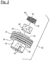
- FIG. 2 is an exploded view of a housing, filter element and stopper comprising the filter assembly
- FIG. 3 is an enlarged sectional view of the tire valve stem, filter assembly and sensing device in an assembled arrangement.
- a tire valve stem 10 is typically provided with external threads 12 and a valve pin 14 that, when depressed, enables air or other gas 35 to pass through the stem and into or out of a tire.
- An electronic sensing/transmitting device 16 such as an air pressure sensor, is typically equipped with a mount 18 having internal threads 20 adapted to engage the outwardly threaded tire stem 10 .
- a filter assembly generally designated 22 , may be interposed between the tire stem 10 and the sensing/transmitting device 16 .
- the filter assembly 22 may comprise a housing 24 , a filter element 26 and a ported retainer 28 .
- the housing 24 may be formed with a mount-engaging, threaded boss 30 , a filter-receiving cavity or bore 32 open at a first end of the housing and a stem-engaging stub 34 at an opposite end of the housing.
- the threaded boss 30 is sized to engage the internal threads 20 on the sensor mount 18 .
- the open end 36 of the filter-receiving cavity is provided with internal threads sized to engage the retainer 28 .
- the stub 34 is sized to project into the tire stem 10 and engage the valve pin 14 so that tire gas 35 can be released.
- At least one, and preferably two, ports 38 extend through the stub to the filter-receiving cavity 32 so that the tire gas 35 reaches the filter 26 .
- the filter is adapted to absorb moisture and block particulate matter before the tire gas reaches the sensor 16 .
- the retainer 28 has external threads 40 that engage the internal threads of the open end 36 of the cavity and is formed with a central bore 42 so that the tire gas passing through the filter reaches the sensor. Diametrically opposing notches 43 or a crosspiece may be formed on an outer end of the retainer 28 to receive a tool (not shown) for rotating the stopper fully into the recess 36 .
- the filter assembly 22 may be screwed into the sensor mount 18 .
- a front gasket 48 may be provided for an air tight seal therebetween.
- the stub 34 may be formed with diametrically opposing notches 39 adjacent to the ports 38 .
- a tool (not shown) may be formed with tines that can be inserted into the notches 39 and then rotated to tighten the threaded filter assembly 22 against the front gasket 48 and the sensor mount 18 .
- a rear gasket 50 may be mounted on the stub 34 to provide an air tight seal between the tire stem 10 , sensor mount 18 and the filter assembly 22 .
- the sensor filters may be changed collectively on a scheduled, preventive maintenance basis, or individually when one becomes too clogged to operate efficiently. If, for instance, the monitor that receives and displays sensor readings indicates that it is no longer receiving signals from a particular sensor, it may be time to change the filter.
Landscapes
- Engineering & Computer Science (AREA)
- Mechanical Engineering (AREA)
- Check Valves (AREA)
- Chemical & Material Sciences (AREA)
- Chemical Kinetics & Catalysis (AREA)
- Measuring Fluid Pressure (AREA)
Abstract
Description
Claims (20)
Priority Applications (1)
| Application Number | Priority Date | Filing Date | Title |
|---|---|---|---|
| US15/620,096 US10792963B2 (en) | 2017-06-12 | 2017-06-12 | Tire sensor filter |
Applications Claiming Priority (1)
| Application Number | Priority Date | Filing Date | Title |
|---|---|---|---|
| US15/620,096 US10792963B2 (en) | 2017-06-12 | 2017-06-12 | Tire sensor filter |
Publications (2)
| Publication Number | Publication Date |
|---|---|
| US20180354321A1 US20180354321A1 (en) | 2018-12-13 |
| US10792963B2 true US10792963B2 (en) | 2020-10-06 |
Family
ID=64562478
Family Applications (1)
| Application Number | Title | Priority Date | Filing Date |
|---|---|---|---|
| US15/620,096 Active 2038-10-17 US10792963B2 (en) | 2017-06-12 | 2017-06-12 | Tire sensor filter |
Country Status (1)
| Country | Link |
|---|---|
| US (1) | US10792963B2 (en) |
Cited By (1)
| Publication number | Priority date | Publication date | Assignee | Title |
|---|---|---|---|---|
| US20230160511A1 (en) * | 2021-11-25 | 2023-05-25 | Scott Wu | Inflation pump connector suitable for various valves |
Citations (4)
| Publication number | Priority date | Publication date | Assignee | Title |
|---|---|---|---|---|
| US6764593B1 (en) * | 2002-11-06 | 2004-07-20 | Scot M. Pace | Automobile air conditioning refrigerant filter |
| US20170009922A1 (en) * | 2015-07-09 | 2017-01-12 | Lung-Kuo Hsu | Quick Connector Structure for a Pneumatic Valve |
| US20180009278A1 (en) * | 2015-02-06 | 2018-01-11 | Dana Limited | Assembly for a tire inflation system and the tire inflation system made therewith |
| US20180339562A1 (en) * | 2017-05-25 | 2018-11-29 | Hsu-Ming Liu | Rapid clipper for inflating tire |
-
2017
- 2017-06-12 US US15/620,096 patent/US10792963B2/en active Active
Patent Citations (4)
| Publication number | Priority date | Publication date | Assignee | Title |
|---|---|---|---|---|
| US6764593B1 (en) * | 2002-11-06 | 2004-07-20 | Scot M. Pace | Automobile air conditioning refrigerant filter |
| US20180009278A1 (en) * | 2015-02-06 | 2018-01-11 | Dana Limited | Assembly for a tire inflation system and the tire inflation system made therewith |
| US20170009922A1 (en) * | 2015-07-09 | 2017-01-12 | Lung-Kuo Hsu | Quick Connector Structure for a Pneumatic Valve |
| US20180339562A1 (en) * | 2017-05-25 | 2018-11-29 | Hsu-Ming Liu | Rapid clipper for inflating tire |
Cited By (2)
| Publication number | Priority date | Publication date | Assignee | Title |
|---|---|---|---|---|
| US20230160511A1 (en) * | 2021-11-25 | 2023-05-25 | Scott Wu | Inflation pump connector suitable for various valves |
| US11971125B2 (en) * | 2021-11-25 | 2024-04-30 | Scott Wu | Inflation pump connector suitable for various valves |
Also Published As
| Publication number | Publication date |
|---|---|
| US20180354321A1 (en) | 2018-12-13 |
Similar Documents
| Publication | Publication Date | Title |
|---|---|---|
| US7454965B2 (en) | Method and apparatus for mounting a tire pressure monitoring device | |
| US20230364953A1 (en) | Inflation manifold | |
| US8915275B2 (en) | Apparatus and system for integration of a central tire inflation valve into a wheel | |
| US20160023523A1 (en) | Tire Pressure Sensor Assembly | |
| CN106660415B (en) | Tyre pressure sensor component and wheel including it | |
| US8567241B2 (en) | Adapter incorporating a TPMS onto a truck tire valve | |
| CN107816564B (en) | Wheel valve assembly with vent to atmosphere | |
| US10465810B2 (en) | Integrated tire inflation valve | |
| US7168468B2 (en) | Vehicle wheel assembly with a hollow stud and internal passageways connected to a CTIS | |
| US20110272038A1 (en) | Adapter incorporating TPMS onto a truck valve | |
| US10792963B2 (en) | Tire sensor filter | |
| US20200254370A1 (en) | Systems and methods for integration of pressure differential sensor | |
| US11529831B2 (en) | Central tire inflation system | |
| US12485709B2 (en) | Central tire inflation system | |
| CN108215676A (en) | It is a kind of can automatic inflating high safety performance device | |
| US20240326522A1 (en) | System for inflating vehicle tires | |
| US10317302B2 (en) | Dual channel pressure sensor with single connection orifice | |
| KR101540695B1 (en) | Bleeder valve for aircraft wheel brake | |
| US9651040B2 (en) | Unloader valve apparatus for an air compressor | |
| US6471755B2 (en) | Gas conducting system with filter for moisture removal | |
| US7625431B2 (en) | Air dryers | |
| US7350408B1 (en) | Apparatus and systems for integration of a sensor into a wheel | |
| GB2446213A (en) | Wheel sensor | |
| US12576676B2 (en) | Automatic tire inflation system hose with integrated TPMS sensor | |
| US7992721B2 (en) | Method and apparatus for confirming that a filter drier has been replaced |
Legal Events
| Date | Code | Title | Description |
|---|---|---|---|
| AS | Assignment |
Owner name: DORAN MANUFACTURING LLC, OHIO Free format text: ASSIGNMENT OF ASSIGNORS INTEREST;ASSIGNORS:JIE, KEVIN SHEN;STEGMAN, JEFFREY;SAMOCKI, JAMES CLIFFORD;REEL/FRAME:042678/0208 Effective date: 20170609 |
|
| STPP | Information on status: patent application and granting procedure in general |
Free format text: DOCKETED NEW CASE - READY FOR EXAMINATION |
|
| STPP | Information on status: patent application and granting procedure in general |
Free format text: NON FINAL ACTION MAILED |
|
| STPP | Information on status: patent application and granting procedure in general |
Free format text: RESPONSE TO NON-FINAL OFFICE ACTION ENTERED AND FORWARDED TO EXAMINER |
|
| STPP | Information on status: patent application and granting procedure in general |
Free format text: FINAL REJECTION MAILED |
|
| STCV | Information on status: appeal procedure |
Free format text: NOTICE OF APPEAL FILED |
|
| STPP | Information on status: patent application and granting procedure in general |
Free format text: NOTICE OF ALLOWANCE MAILED -- APPLICATION RECEIVED IN OFFICE OF PUBLICATIONS |
|
| STPP | Information on status: patent application and granting procedure in general |
Free format text: PUBLICATIONS -- ISSUE FEE PAYMENT VERIFIED |
|
| STCF | Information on status: patent grant |
Free format text: PATENTED CASE |
|
| MAFP | Maintenance fee payment |
Free format text: PAYMENT OF MAINTENANCE FEE, 4TH YR, SMALL ENTITY (ORIGINAL EVENT CODE: M2551); ENTITY STATUS OF PATENT OWNER: SMALL ENTITY Year of fee payment: 4 |