US10792445B2 - Spacer chamber comprising an operating means for an inhaler - Google Patents
Spacer chamber comprising an operating means for an inhaler Download PDFInfo
- Publication number
- US10792445B2 US10792445B2 US14/804,560 US201514804560A US10792445B2 US 10792445 B2 US10792445 B2 US 10792445B2 US 201514804560 A US201514804560 A US 201514804560A US 10792445 B2 US10792445 B2 US 10792445B2
- Authority
- US
- United States
- Prior art keywords
- inhaler
- lever
- chamber
- housing chamber
- spacer
- Prior art date
- Legal status (The legal status is an assumption and is not a legal conclusion. Google has not performed a legal analysis and makes no representation as to the accuracy of the status listed.)
- Active, expires
Links
- 125000006850 spacer group Chemical group 0.000 title claims abstract description 58
- 230000004913 activation Effects 0.000 claims abstract description 21
- 239000000443 aerosol Substances 0.000 claims description 20
- 210000000214 mouth Anatomy 0.000 claims description 17
- 229940126601 medicinal product Drugs 0.000 claims description 13
- 230000037431 insertion Effects 0.000 claims 1
- 238000003780 insertion Methods 0.000 claims 1
- 230000001681 protective effect Effects 0.000 description 6
- 230000000694 effects Effects 0.000 description 4
- 229940071648 metered dose inhaler Drugs 0.000 description 4
- 230000004048 modification Effects 0.000 description 3
- 238000012986 modification Methods 0.000 description 3
- 238000003825 pressing Methods 0.000 description 3
- 230000008859 change Effects 0.000 description 2
- 238000004140 cleaning Methods 0.000 description 2
- 238000010276 construction Methods 0.000 description 2
- 239000003380 propellant Substances 0.000 description 2
- 208000023504 respiratory system disease Diseases 0.000 description 2
- 238000010521 absorption reaction Methods 0.000 description 1
- 230000006978 adaptation Effects 0.000 description 1
- 239000000853 adhesive Substances 0.000 description 1
- 230000001070 adhesive effect Effects 0.000 description 1
- 238000003491 array Methods 0.000 description 1
- 239000003292 glue Substances 0.000 description 1
- 239000007788 liquid Substances 0.000 description 1
- 230000007246 mechanism Effects 0.000 description 1
- 229940127554 medical product Drugs 0.000 description 1
- 239000002184 metal Substances 0.000 description 1
- 238000000034 method Methods 0.000 description 1
- 210000002200 mouth mucosa Anatomy 0.000 description 1
- 230000008569 process Effects 0.000 description 1
- 230000007704 transition Effects 0.000 description 1
Images


Classifications
-
- A—HUMAN NECESSITIES
- A61—MEDICAL OR VETERINARY SCIENCE; HYGIENE
- A61M—DEVICES FOR INTRODUCING MEDIA INTO, OR ONTO, THE BODY; DEVICES FOR TRANSDUCING BODY MEDIA OR FOR TAKING MEDIA FROM THE BODY; DEVICES FOR PRODUCING OR ENDING SLEEP OR STUPOR
- A61M15/00—Inhalators
- A61M15/0086—Inhalation chambers
-
- A—HUMAN NECESSITIES
- A61—MEDICAL OR VETERINARY SCIENCE; HYGIENE
- A61M—DEVICES FOR INTRODUCING MEDIA INTO, OR ONTO, THE BODY; DEVICES FOR TRANSDUCING BODY MEDIA OR FOR TAKING MEDIA FROM THE BODY; DEVICES FOR PRODUCING OR ENDING SLEEP OR STUPOR
- A61M15/00—Inhalators
- A61M15/0001—Details of inhalators; Constructional features thereof
- A61M15/0021—Mouthpieces therefor
-
- A—HUMAN NECESSITIES
- A61—MEDICAL OR VETERINARY SCIENCE; HYGIENE
- A61M—DEVICES FOR INTRODUCING MEDIA INTO, OR ONTO, THE BODY; DEVICES FOR TRANSDUCING BODY MEDIA OR FOR TAKING MEDIA FROM THE BODY; DEVICES FOR PRODUCING OR ENDING SLEEP OR STUPOR
- A61M15/00—Inhalators
- A61M15/0065—Inhalators with dosage or measuring devices
-
- A—HUMAN NECESSITIES
- A61—MEDICAL OR VETERINARY SCIENCE; HYGIENE
- A61M—DEVICES FOR INTRODUCING MEDIA INTO, OR ONTO, THE BODY; DEVICES FOR TRANSDUCING BODY MEDIA OR FOR TAKING MEDIA FROM THE BODY; DEVICES FOR PRODUCING OR ENDING SLEEP OR STUPOR
- A61M15/00—Inhalators
- A61M15/009—Inhalators using medicine packages with incorporated spraying means, e.g. aerosol cans
Definitions
- the invention relates to a spacer chamber comprising an operating means for an inhaler.
- an aerosol For the treatment of patients with respiratory diseases it is known to supply medicinal products in the form of an aerosol to patients.
- the aerosol is frequently supplied with the aid of an inhaler (also referred to as an MDI—metered-dose inhaler).
- MDI tered-dose inhaler
- Such an inhaler includes a container accommodating the medicinal product in liquid form.
- a dosage means leading to a mouth element which can be taken by the operator into his/her mouth in the case of application, is arranged at the outlet of the container accommodated in a holder.
- Application is effected frequently by the operator by pressing on the bottom of the inhaler, whereby a predetermined amount of the medicinal product is made available as an aerosol in the form of a puff via the dosage means.
- the mouth element forms an integral unit with the holder usually consisting of plastic.
- the dosage means is mounted on the container.
- any intended absorption of the medicinal product requires from the patient to press on the activation element and/or the container of the inhaler at the same time and breathe in the aerosol via the mouth at the same time.
- This coordination of two processes at the same time can overstrain very sick patients, but also children or the elderly.
- the aerosol dosage is introduced into the patient's oral cavity via the mouthpiece only, but is not inhaled into the airways.
- the medicinal product drops in the aerosol then adhere to the oral mucosa and cannot fulfil their predetermined effect.
- spacer chambers have been developed, which can be inserted between the mouth element of the inhaler and the patient's mouth.
- a spacer chamber includes a housing chamber and/or a cavity on which a connecting means is provided to which an inhaler not belonging to the spacer chamber can be attached. Furthermore, a mouthpiece is available for the patient on the cavity. The patient or a helper can then first of all operate the inhaler, whereby the medicinal product aerosol enters the spacer chamber. In a separate, chronologically subsequent step, the patient can then breathe in the aerosol via the mouthpiece.
- inhalation can be chronologically equalized with the aid of such a spacer chamber. It is no longer required to operate the inhaler and breathe in at the same time. Rather, the inhaler can first of all be operated to produce the aerosol and only then, under circumstances a few seconds later, the aerosol can be breathed in.
- spacer chambers have proved themselves very well in practice, it has been found that, due to the size of the spacer chambers, their operation usually requires two hands. For example, the spacer chamber must be held with one hand, while the inhaler is activated with the other hand. Especially for babies this can be problematic, since the parents must hold the child with at least one hand, so that only one free hand is available with which the spacer chamber must then be held to the child's mouth and the inhaler activated at the same time.
- spacer chambers have been developed where the inhaler can each been activated with the aid of levers.
- Such spacer chambers and/or arrays of spacer chambers and inhalers are, for example, described in U.S. Pat. Nos. 8,695,589 B2, 6,453,900 B1, and US 2007/0074718 A1.
- the well-known devices are constructed in a relatively complex manner and require a complete new development of the spacer chamber in each case.
- the inhalers cannot be used in the standard sales appearance, i.e. with mouthpiece.
- the invention is based on the object to provide a spacer chamber for an inhaler which is constructed in a simple manner, and where the inhaler can be inserted complete in a ready-to-use state.
- an inhalation device comprising the spacer chamber and an inhaler is also provided.
- a spacer chamber for an inhaler includes a housing chamber as well as a mouthpiece arranged on the housing chamber, a connecting means arranged on the housing chamber to connect the inhaler, and an operating means held on the housing chamber.
- the operating means is movable to two positions and includes an active surface which is arranged in such a manner that the active surface can act on an activation element of the inhaler in any one of the positions of the operating means, if the inhaler is connected to the connecting means.
- the mouthpiece can be provided on one side of the housing chamber, while the connecting means can be arranged remote from the mouthpiece, e.g. opposite to the mouthpiece, on the housing chamber. If the housing chamber has an essentially cylindrical, tubular form, the mouthpiece can then be provided on one front side and the connecting means on the opposite front side.
- the connecting means can be shaped annular, releasably fastened and formed on the housing chamber to releasably carry the inhaler. In doing so, it is particularly practical, if the housing chamber has a cylindrical, tubular basic form.
- the connecting means can then be inserted into and/or clamped onto the front side, opposite to the mouthpiece.
- the operating means can include a lever means, with the lever means able to include a lever element and a lever carrier carrying the lever element, and the lever element is movable, in particular swivelable, relative to the lever carrier.
- the movability of the lever element relative to the lever carrier can also be effected in the form of a linear movement.
- the lever element is slidable relative to the lever carrier.
- the lever carrier can be fastened, in particular, releasably fastened, to the housing chamber.
- the fastening can, for example, be to the housing chamber in the vicinity of the mouthpiece, so that the lever element extends away from the mouthpiece and the lever carrier along the middle axis of the housing chamber to the opposite connecting means and thus the inhaler.
- a hinge means can be arranged between the lever element and the lever carrier, with the lever element being swivelable relative to the lever carrier due to the hinge means.
- the hinge means thus effects a rotatory degree of freedom for the lever element.
- spring elastic elasticity of the lever element is possible.
- the lever element can have an elongated extension and be held on the level carrier on a carrier-sided end.
- the active surface can be formed on the other inhaler-sided end of the lever element opposite to the lever carrier.
- a safety means can be provided to support the inhaler on at least one side in order to prevent the inhaler from twisting around a middle axis of the housing chamber relative to the connecting means.
- the connecting means For proper operation of the inhaler it is necessary that the inhaler is reliably held by the connecting means.
- By twisting the inhaler relative to the connecting means there is a risk that the inhaler will drop out of the connecting means. This can, in particular, happen during a transport of the inhaler with the spacer chamber. With the aid of the safety means unintended twisting of the inhaler is avoided, as the inhaler is held in its position relative to the connecting means.
- a supporting means can be provided on the inhaler-sided end of the lever element to support the inhaler on its rearward side facing away from the position of the lever element. It has been noted that when the lever element is operated, there is a risk that the inhaler and/or the container of the inhaler will bend backward, away from the spacer chamber, due to diagonally acting forces exerted by the lever element. Thus, the inhaler can be pressed out of the connecting means. To prevent this, the supporting means can be provided, with which the inhaler is supported rearward, i.e. on the side facing away from the spacer chamber. Thus, the inhaler is reliably held within the connecting means.
- the safety means or the supporting means can each have a surface formed on the inhaler-sided end of the lever element.
- Another modification of the spacer chamber is not required, so that—as already mentioned above—also for the housing chamber a housing chamber can be used as it is known for spacer chambers from the prior art, on which a correspondingly formed lever element with various surfaces can be mounted.
- a change of the position of the active surface relative to the grip area can be practicable to adjust the device to inhalers of different sizes.
- the activation element comes to rest at various points and/or at different height levels, so that the distance between the active surface and the activation element varies.
- the position of the active surface can be changed, for example, by shifting or bolting down the element on which the active surface is provided.
- the lever element can, in particular, be divided into at least two parts whose distance to each other is adjustably variable.
- the connecting means can be held on a front side of the housing chamber and can be twistable on this front side to at least three positions, namely to a first rotational position in which the inhaler is held within the connecting means and the connecting means is held within the housing chamber, to a second rotational position in which the inhaler is removable from the connecting means and the connecting means is held within the housing chamber, and to a third rotational position in which the connecting means is removable from the front side of the housing chamber.
- the inhaler is a standard inhaler with which normally medicinal products for the treatment of respiratory diseases or similar are administered.
- Such an inhaler is also diversely known as an MDI (metered-dose inhaler).
- FIG. 1 shows an inhalation device comprising a spacer chamber and an inhaler in side view
- FIG. 2 a shows a sectional view of an inhalation device in side view
- FIG. 2 b shows the inhalation device of FIG. 2 a in top view
- FIG. 3 a shows a spacer chamber in side view
- FIG. 3 b shows a sectional view of the spacer chamber of FIG. 3 a with a mounted lever means
- FIG. 4 shows a sectional view of a spacer chamber in side view
- FIG. 5 shows a sectional view of an inhalation device in side view
- FIG. 6 shows a detailed view in top view
- FIG. 7 shows variants of an inhaler-sided lever end
- FIG. 8 shows a top view on an inhaler-sided end of a spacer chamber
- FIG. 9 a shows a rear view of an inhalation device
- FIG. 9 b shows the inhalation device of FIG. 9 a with a twisted inhaler and a twisted connecting means
- FIG. 10 shows a side view of a variant of an inhalation device
- FIG. 11 shows another variant of an inhalation device in sectional view
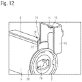
- FIG. 12 shows a perspective sectional view of a spacer chamber comprising a locking means
- FIG. 13 shows a schematic sectional view of an inhalation device comprising a locking means
- FIG. 14 shows a sectional view of an inhalation device for inhalers of various sizes.
- FIG. 1 shows an inhalation device comprising a spacer chamber 1 and an inhaler 2 in side view.
- the inhaler 2 is a customary inhaler (also referred to as an MDI—metered-dose inhaler) with which a medicinal product in a predetermined dosage is converted into an aerosol, which can be inhaled by a patient via a mouthpiece not visible in FIG. 1 .
- a container 3 containing the medicinal product and a propellant gas is inserted, in particular screwed, into a holder 4 .
- the (non-visible) mouth element is designed integrally on the holder 4 .
- the spacer chamber 1 includes a housing chamber 5 , which essentially corresponds to a hollow cylindrical tube and is covered on the front sides.
- a mouthpiece 6 which, for example, can be provided with a check valve, is provided on a front side.
- the mouthpiece 6 is covered by a protective cover 6 a in FIG. 1 .
- a connecting means 7 is mounted, which, on one hand, closes the housing chamber 5 in a cover-like manner and, on the other hand, forms the connecting possibility to connect the inhaler 2 .
- An opening which is not visible in FIG. 1 , is formed in the connecting means 7 , into which the mouth element of the inhaler 2 can be inserted. In that manner, the inhaler 2 is held safely on the housing chamber 5 .
- a lever means 8 which serves as an operating means, is mounted on the outside of the housing chamber 5 .
- the lever means 8 includes a lever 9 serving as a lever element, which is held on the housing chamber 5 by a lever carrier 10 .
- the lever 9 is designed in such a manner that it extends from the lever carrier 10 arranged in the vicinity of the mouthpiece 6 along the middle axis of the housing chamber 5 rearwards in the direction of the inhaler 2 and there encloses the bottom 3 a of the container 3 of the inhaler 2 .
- the lever 9 is movably held on the housing chamber 5 via the lever carrier 10 , i.e. is movable and/or swivelable relative to the lever carrier 10 .
- the lever 9 and the lever carrier 10 have a certain movability which enables, in particular, that the inhaler-sided end of the lever 9 can be moved in such a manner that an active surface 11 formed on the end can press on the bottom 3 a of the container 3 to activate a puff.
- an operator of the inhalation device can hold the housing chamber 5 with the lever 9 with one hand and swivel the lever 9 in the direction of the housing chamber 5 . In doing so, the operator can press on a grip area 9 a of the lever 9 .
- the active surface 11 is displaced and pressed against the bottom 3 a of the inhaler container 3 , whereby a puff can be activated.
- the aerosol from the container 3 enters the interior of the housing chamber 5 via the mouth element of the inhaler 2 and the connecting means 7 , and can be inhaled there by the patient.
- the lever carrier 10 can be elastic and hold the relatively rigid lever 9 , which is then movable through its connection.
- a hinge means is formed between the lever carrier 10 and the lever 9 to achieve the movability of the lever 9 .
- the hinge means can be designed as a hinge with an additional axis element.
- the hinge means can also be designed as a simple film hinge.
- the lever carrier 10 can be firmly connected with the housing chamber 5 .
- the lever carrier 10 which, for example, can be designed annular and thus encloses the housing chamber 5 , can be designed in the form of a clamp which is screwed on the housing chamber 5 .
- lever carrier 10 is merely clipped or pushed onto the housing chamber 5 .
- the lever carrier 10 can also be slid into a pocket or a ring provided on the housing chamber 5 .
- FIG. 2 a shows a variant for the fastening of the lever 9 and/or of the lever carrier 10 in side view
- FIG. 2 b shows the arrangement of FIG. 2 a in top view.
- a circumferential recess 12 in the form of a groove, a joint or of a cut-in, into which the lever carrier 10 is inserted, is provided in the outside wall of the housing chamber 5 .
- the lever carrier 10 in the illustrated example is shown as an open clasp which is clipped into the recess 12 .
- a hinge means 13 is provided in the form of a swivel. With the aid of the hinge means 13 it is easily possible to swivel the lever 9 relative to the lever carrier 10 and the housing chamber 5 .
- FIG. 3 a the housing chamber 5 is shown with the recess 12 , however, without the lever carrier 10 .
- FIG. 3 b a simplified arrangement is shown where the lever carrier 10 is also inserted into the recess 12 in the form of a mounting clip.
- the lever 9 is connected with the lever carrier 10 . Since the lever 9 has a certain degree of elasticity, in particular, spring elasticity, no additional hinge means is required to achieve movability of the lever 9 .
- lever 9 and the lever carrier 10 can be manufactured integrally in the form of the entire lever means 8 , for example, from plastic or from metal.
- FIG. 4 shows another variant where the lever carrier 10 and the lever 9 are designed rather rigid, and the lever 9 can be swiveled with respect to the lever carrier 10 due to the hinge means 13 arranged therebetween.
- a transportation lock 14 is provided.
- the transportation lock 14 can be integrated into the protective cover 6 a for the mouthpiece 6 , i.e. be part of the protective cover 6 a, or also be integrated into the mouthpiece 6 .
- the effect of the transportation lock 14 is achieved in that the carrier 9 is extended beyond the hinge means 13 in the direction of the mouthpiece 6 , and grips with this extension underneath the protective cover 6 a and/or transportation lock 14 . Therefore, if the protective cover 6 a designed as a cap, for example, is mounted as shown in FIG. 4 , the protective cover 6 a as the transportation lock 14 overlaps the extended end of the lever 9 and blocks its movement.
- FIG. 5 shows another variant, where the design of the inhaler-sided end of the lever 9 is meant to be contemplated now.
- the active surface 11 is formed on a bracket which projects above the bottom 3 a of the container 3 .
- the lever 9 itself forms a lateral supporting surface 15 which serves as a safety means and supports the inhaler 2 in the operating position. Thus, it is prevented that the inhaler 2 can be twisted undesirably relative to the housing chamber 5 .
- the inhaler 2 is held in the intended operating position through the design of the end of the lever 9 .
- the lateral supporting surface 15 turns into a rearward supporting surface 16 which serves as a supporting means.
- a force is exerted on the inhaler 2 in the embodiment shown, as a result of which the inhaler 2 has the tendency to be pressed out of the connecting means 7 .
- the rearward supporting surface 16 is provided to hold the inhaler 2 reliably within the connecting means 7 . Thus, rearward evasion of the inhaler 2 , away from the housing chamber 5 and the connecting means 7 , is prevented.
- the supporting function of the supporting surface 16 is not required.
- FIG. 6 shows a variant of the inhaler-sided end of the lever 9 in top view.
- the lateral supporting surface 15 encloses the inhaler 2 in an annular manner.
- the bottom 3 a of the inhaler 2 is covered by the arc-shaped active surface 11 .
- FIG. 7 shows further variants for the design of the inhaler-sided end of the lever 9 in top and side view.
- the lateral supporting surface 15 encompasses the inhaler 2 only partly, and thus enables to swivel the inhaler 2 around the middle and/or longitudinal axis of the housing chamber 5 .
- the lateral supporting surface 15 can turn into the rearward supporting surface 16 in a transition-free manner, as, for example, as shown in FIGS. 6 and 7 .
- FIG. 8 shows a variant where a lateral supporting surface 17 is not formed on the end of the carrier 9 , but on the connecting means 7 . It can be seen from the illustration of FIG. 8 in top view that the inhaler 2 cannot be twisted at will relative to the housing chamber 5 and/or the connecting means 7 , as it is held in a vertical position by the lateral supporting surface 17 . Embodiments comprising two lateral supporting surfaces can also be advantageous.
- FIG. 9 a shows a perspective view of another variant in the operating position.
- FIG. 9 b shows the variant in a position where the inhaler 2 can be removed.
- the inhaler 2 is, similar to the variants shown in FIGS. 5 to 7 , partly enclosed by the end of the carrier 9 , so that the active surface 11 comes to rest opposite to the bottom 3 a of the container 3 , the lateral supporting surface 15 prevents twisting of the inhaler 2 in one direction, and the rearward supporting surface 16 blocks evasion of the inhaler 2 away from the housing chamber 5 .
- the lateral supporting surface 17 is provided on the annular connecting means 7 , which blocks twisting of the inhaler 2 in a direction opposite to the lateral supporting surface 15 .
- the inhaler 2 can only be released through twisting together with the connecting means 7 , as shown by FIG. 9 b.
- connecting means 7 it is possible to twist the connecting means 7 to a total of three positions, namely to the positions according to FIGS. 9 a and 9 b as well as to another position (based on FIG. 9 b at 90° counterclockwise). In the latter position the connecting means can then be demounted from the housing chamber 5 , to obtain, for example, free access to the housing chamber 5 for cleaning purposes. In doing so, it can be practical, if the connecting means 7 is fastened to the housing chamber 5 through a bayonet catch.
- FIG. 10 shows another variant where the lever carrier 10 is provided on the inhaler-sided end of the housing chamber 5 .
- the hinge means 13 is arranged which enables swiveling of the lever 9 relative to the housing chamber 5 .
- the operator must press against the grip area 9 a of the lever 9 (in the direction of the arrow)—in FIG. 10 from below—to activate a puff.
- the grip area 9 a of the lever 9 in the direction of the arrow
- the opposite active surface 11 is lowered and operates the container bottom 3 a.
- FIG. 11 shows another variant where, in addition to the lever 9 , a grip 18 is provided on the housing chamber 5 to enable the operator to support his/her hand.
- FIG. 12 shows an embodiment comprising a locking means 19 .
- the locking means 19 is provided, which is to prevent unintended movement of the lever 9 .
- the locking means 19 includes a locking ring 20 with a locking extension 21 enclosing the housing chamber 5 .
- a recess 22 is provided in the locking appendage 21 , which can be guided to the position shown in FIG. 12 via the lever 9 . Thus, the lever 9 is blocked in the position shown. In particular, the active surface 11 cannot press on the inhaler 2 (locking state).
- FIG. 13 shows another example for a possible locking means 19 .
- the lever 9 is movable axially in two latching steps relative to the housing chamber 5 .
- the latching steps are determined by a latching means 23 .
- part of the lever 9 is located directly above a stop 24 .
- the lever 9 can only minimally be moved downward in the direction of the inhaler 2 .
- accidental activation of a puff is prevented.
- FIG. 14 shows a variant where the inhalation device is adjustable to various sizes of inhalers 2 .
- the position of the active surface 11 is changeable relative to the remaining lever 9 .
- the active surface 11 is designed on a cover 25 which is screwable relative to the lever 9 .
- the active surface 11 is at a different height with respect to the lever 9 and the inhaler 2 .
- the position of the cover 25 can be fixed, for example, by a relatively tight-fitting thread 26 between the end of the lever 9 and the cover 25 .
- the cover 25 can also serve as a cap for the mouthpiece 6 , if the spacer chamber is not used.
Landscapes
- Health & Medical Sciences (AREA)
- Engineering & Computer Science (AREA)
- Life Sciences & Earth Sciences (AREA)
- Heart & Thoracic Surgery (AREA)
- Anesthesiology (AREA)
- Biomedical Technology (AREA)
- Pulmonology (AREA)
- Hematology (AREA)
- Bioinformatics & Cheminformatics (AREA)
- Animal Behavior & Ethology (AREA)
- General Health & Medical Sciences (AREA)
- Public Health (AREA)
- Veterinary Medicine (AREA)
- Biophysics (AREA)
- Containers And Packaging Bodies Having A Special Means To Remove Contents (AREA)
Abstract
Description
Claims (14)
Applications Claiming Priority (3)
| Application Number | Priority Date | Filing Date | Title |
|---|---|---|---|
| DE102014011271.3 | 2014-07-29 | ||
| DE102014011271.3A DE102014011271A1 (en) | 2014-07-29 | 2014-07-29 | Ballast chamber with control element for inhaler |
| DE102014011271 | 2014-07-29 |
Publications (2)
| Publication Number | Publication Date |
|---|---|
| US20160030688A1 US20160030688A1 (en) | 2016-02-04 |
| US10792445B2 true US10792445B2 (en) | 2020-10-06 |
Family
ID=53284013
Family Applications (1)
| Application Number | Title | Priority Date | Filing Date |
|---|---|---|---|
| US14/804,560 Active 2038-03-27 US10792445B2 (en) | 2014-07-29 | 2015-07-21 | Spacer chamber comprising an operating means for an inhaler |
Country Status (3)
| Country | Link |
|---|---|
| US (1) | US10792445B2 (en) |
| EP (1) | EP2979718B1 (en) |
| DE (1) | DE102014011271A1 (en) |
Families Citing this family (2)
| Publication number | Priority date | Publication date | Assignee | Title |
|---|---|---|---|---|
| WO2017040391A1 (en) * | 2015-08-28 | 2017-03-09 | The Research Institute At Nationwide Children's Hospital | Interactive spacer for respiratory device |
| CN109152891B (en) * | 2016-03-24 | 2022-11-08 | 特鲁德尔医学国际公司 | Respiratory care system with electronic indicator |
Citations (12)
| Publication number | Priority date | Publication date | Assignee | Title |
|---|---|---|---|---|
| US3405843A (en) | 1966-11-23 | 1968-10-15 | Cornelius B. Watson Jr. | Container-dispenser for collapsible tubes |
| US4592348A (en) | 1984-12-17 | 1986-06-03 | Waters Iv William C | Aerosol inhaler |
| US6453900B1 (en) | 2000-06-09 | 2002-09-24 | Pulmonary Services, Inc. | Inhaler device |
| US20020157664A1 (en) | 2001-03-12 | 2002-10-31 | Eric Fugelsang | Canister inhaler having a spacer and easy to operate lever mechanism and a flexible, elastic mouthpiece |
| EP1358901A2 (en) | 2002-05-02 | 2003-11-05 | PARI Innovative Manufactures Inc. | Aerosol medication inhalation system |
| US20040055596A1 (en) * | 2000-12-05 | 2004-03-25 | Bacon Raymond John | Drug dispenser |
| US20060076011A1 (en) * | 1999-11-08 | 2006-04-13 | Capnia, Incorporated | Methods and apparatus for the enhanced delivery of physiologic agents to tissue surfaces |
| US20070074718A1 (en) * | 2005-10-04 | 2007-04-05 | Sp Medical Llc | Metered dose inhaler having spacing device |
| WO2009052563A1 (en) * | 2007-10-24 | 2009-04-30 | Stirling Products Limited | Inhaler assembly |
| US20120103326A1 (en) * | 2009-06-25 | 2012-05-03 | Boehringer Ingelheim Vetmedica Gmbh | Inhaler |
| US8659589B2 (en) | 2008-12-29 | 2014-02-25 | Microsoft Corporation | Leveraging graphics processors to optimize rendering 2-D objects |
| US8695589B2 (en) | 2011-12-06 | 2014-04-15 | Anthony J. Mullane | Inhaler assist device |
-
2014
- 2014-07-29 DE DE102014011271.3A patent/DE102014011271A1/en not_active Withdrawn
-
2015
- 2015-05-22 EP EP15168987.4A patent/EP2979718B1/en active Active
- 2015-07-21 US US14/804,560 patent/US10792445B2/en active Active
Patent Citations (15)
| Publication number | Priority date | Publication date | Assignee | Title |
|---|---|---|---|---|
| US3405843A (en) | 1966-11-23 | 1968-10-15 | Cornelius B. Watson Jr. | Container-dispenser for collapsible tubes |
| US4592348A (en) | 1984-12-17 | 1986-06-03 | Waters Iv William C | Aerosol inhaler |
| US20060076011A1 (en) * | 1999-11-08 | 2006-04-13 | Capnia, Incorporated | Methods and apparatus for the enhanced delivery of physiologic agents to tissue surfaces |
| US6453900B1 (en) | 2000-06-09 | 2002-09-24 | Pulmonary Services, Inc. | Inhaler device |
| US20040055596A1 (en) * | 2000-12-05 | 2004-03-25 | Bacon Raymond John | Drug dispenser |
| US20020157664A1 (en) | 2001-03-12 | 2002-10-31 | Eric Fugelsang | Canister inhaler having a spacer and easy to operate lever mechanism and a flexible, elastic mouthpiece |
| EP1358901A2 (en) | 2002-05-02 | 2003-11-05 | PARI Innovative Manufactures Inc. | Aerosol medication inhalation system |
| EP2008678A2 (en) | 2002-05-02 | 2008-12-31 | PARI Innovative Manufactures Inc. | Aerosol medication inhalation system |
| US7562656B2 (en) | 2002-05-02 | 2009-07-21 | Hydrate, Inc. | Aerosol medication inhalation system |
| US20070074718A1 (en) * | 2005-10-04 | 2007-04-05 | Sp Medical Llc | Metered dose inhaler having spacing device |
| WO2007041669A2 (en) | 2005-10-04 | 2007-04-12 | Sp Medical Llc | Metered dose inhaler having spacing device |
| WO2009052563A1 (en) * | 2007-10-24 | 2009-04-30 | Stirling Products Limited | Inhaler assembly |
| US8659589B2 (en) | 2008-12-29 | 2014-02-25 | Microsoft Corporation | Leveraging graphics processors to optimize rendering 2-D objects |
| US20120103326A1 (en) * | 2009-06-25 | 2012-05-03 | Boehringer Ingelheim Vetmedica Gmbh | Inhaler |
| US8695589B2 (en) | 2011-12-06 | 2014-04-15 | Anthony J. Mullane | Inhaler assist device |
Also Published As
| Publication number | Publication date |
|---|---|
| EP2979718B1 (en) | 2018-03-28 |
| DE102014011271A1 (en) | 2016-02-04 |
| EP2979718A1 (en) | 2016-02-03 |
| US20160030688A1 (en) | 2016-02-04 |
Similar Documents
| Publication | Publication Date | Title |
|---|---|---|
| US20070221211A1 (en) | Apparatus and process for inhaling medicines | |
| ES2243277T3 (en) | INHALER. | |
| ES2291310T3 (en) | AN INHALATION ACTIVATED DEVICE. | |
| JP2019502368A (en) | Refill dispenser for refilling electronic cigarette cartridges | |
| NO334854B1 (en) | The inhaler device. | |
| US20070074718A1 (en) | Metered dose inhaler having spacing device | |
| NO792917L (en) | Inhalation-DEVICE. | |
| EP1030704A1 (en) | Inhalation device | |
| BR112013006254B1 (en) | VALVULATED INHALATION CHAMBER | |
| JP2019511328A (en) | Intake synchronous fluid discharge device | |
| US20140190473A1 (en) | Inhalation pen | |
| US10792445B2 (en) | Spacer chamber comprising an operating means for an inhaler | |
| US20170100551A1 (en) | Wearable Wrist Inhaler | |
| US20160101248A1 (en) | Wearable Wrist Inhaler | |
| US20070233012A1 (en) | Multi-chamber spray container and system | |
| US20140251321A1 (en) | Inhaler mouthpiece | |
| JP2014515949A5 (en) | ||
| WO2008091355A3 (en) | Drug transfer device | |
| JP2020533152A (en) | Nebulizer and its nozzle assembly | |
| US20170014584A1 (en) | Inhaler mouthpiece | |
| JP2012510827A (en) | Nasal spray device | |
| WO2004105844A1 (en) | Inhalation type dosing device | |
| US20190015607A1 (en) | Dual Chamber Nebulizer Apparatus | |
| GB2547279A (en) | Inhaler device | |
| US20210187212A1 (en) | Inhaler and method |
Legal Events
| Date | Code | Title | Description |
|---|---|---|---|
| AS | Assignment |
Owner name: PARI GMBH SPEZIALISTEN FUER EFFEKTIVE INHALATION, GERMANY Free format text: ASSIGNMENT OF ASSIGNORS INTEREST;ASSIGNORS:KRUEGER, ULF;JELOVAC, EMIR;LOHRE, BIRGIT;REEL/FRAME:036739/0296 Effective date: 20150723 Owner name: PARI GMBH SPEZIALISTEN FUER EFFEKTIVE INHALATION, Free format text: ASSIGNMENT OF ASSIGNORS INTEREST;ASSIGNORS:KRUEGER, ULF;JELOVAC, EMIR;LOHRE, BIRGIT;REEL/FRAME:036739/0296 Effective date: 20150723 |
|
| STPP | Information on status: patent application and granting procedure in general |
Free format text: ADVISORY ACTION MAILED |
|
| STPP | Information on status: patent application and granting procedure in general |
Free format text: DOCKETED NEW CASE - READY FOR EXAMINATION |
|
| STPP | Information on status: patent application and granting procedure in general |
Free format text: NON FINAL ACTION MAILED |
|
| STPP | Information on status: patent application and granting procedure in general |
Free format text: RESPONSE TO NON-FINAL OFFICE ACTION ENTERED AND FORWARDED TO EXAMINER |
|
| STPP | Information on status: patent application and granting procedure in general |
Free format text: FINAL REJECTION MAILED |
|
| STPP | Information on status: patent application and granting procedure in general |
Free format text: ADVISORY ACTION MAILED |
|
| STPP | Information on status: patent application and granting procedure in general |
Free format text: NOTICE OF ALLOWANCE MAILED -- APPLICATION RECEIVED IN OFFICE OF PUBLICATIONS |
|
| STPP | Information on status: patent application and granting procedure in general |
Free format text: PUBLICATIONS -- ISSUE FEE PAYMENT RECEIVED |
|
| STCF | Information on status: patent grant |
Free format text: PATENTED CASE |
|
| MAFP | Maintenance fee payment |
Free format text: PAYMENT OF MAINTENANCE FEE, 4TH YEAR, LARGE ENTITY (ORIGINAL EVENT CODE: M1551); ENTITY STATUS OF PATENT OWNER: LARGE ENTITY Year of fee payment: 4 |