US1079110A - Adjustable square and bevel. - Google Patents
Adjustable square and bevel. Download PDFInfo
- Publication number
- US1079110A US1079110A US76394?13A US1079110DA US1079110A US 1079110 A US1079110 A US 1079110A US 1079110D A US1079110D A US 1079110DA US 1079110 A US1079110 A US 1079110A
- Authority
- US
- United States
- Prior art keywords
- lho
- bevel
- slot
- adjustable square
- tho
- Prior art date
- Legal status (The legal status is an assumption and is not a legal conclusion. Google has not performed a legal analysis and makes no representation as to the accuracy of the status listed.)
- Expired - Lifetime
Links
Images
Classifications
-
- G—PHYSICS
- G01—MEASURING; TESTING
- G01B—MEASURING LENGTH, THICKNESS OR SIMILAR LINEAR DIMENSIONS; MEASURING ANGLES; MEASURING AREAS; MEASURING IRREGULARITIES OF SURFACES OR CONTOURS
- G01B3/00—Measuring instruments characterised by the use of mechanical techniques
- G01B3/56—Gauges for measuring angles or tapers, e.g. conical calipers
Definitions
- 716 may con/ism B9 Lil lmrji'wn that l, .l aana Com, :1, cilia an of tho United States, anl rcsidunl; oi Conway. in lhe county oi? llarroll and till-ah: of New llan'ipshiro, ha e invnnhiad now and usn'l ul linprowinnnls in illljin-zslahle ll'll'llll'lllri and Bowls, oi which tho following ir. a speniii-cn ion.
- Two metal. angrln inonihnrs or .wlIlll'llS are ndjushihly and rvmorahly mounlrll on said basil, each having; a guiding arni (Z, overlying and slidnhly secured in the hasn. and an uprigid arm n disposed al right angina lo the arm (A The arm (l in prl'i'lerahly oi the snow width an tho has-1n upon Whirh.
- i-lllii- 1) all: lua olnrl an lu nL shown: in Figs 3 -l and 5, nncl the tongues are similarly hovnll d, so that when the arnr-i (l are c amped on in the ham aw lwruinnf'lnr dosrrihell the how olrd surl'am-s-a nl' Lho longnirs nngzaggn the hernllnl bllllfiililll'-l oi lho slot, llini'oln; insuring lindd; kill and prnrnnling lhn i iaaihility oli any lalrral play or loowinrss helwnon lihn angglla llllllllfl andit hnao.
- Thumb arrows j are screwed on lo said studs in, and springs are inll-r oavd hvtwcrn the llunnb sari-airs j and the arms (Z.
- lhvy may ill, n'mdn without manipulatinn' lhv srrrws laid angle nu uihcrs may hn wholly rmnovvd h sliding lluun length- ⁇ YiHL' out oi rngaggmnmil ⁇ vilh slot I), whereupon if duxired liufv may he reversed. right for left and vim: ⁇ llnn, and applied as shown in doth-d lines in Fig. 1, with the arms: (I (mending ouhwirdly inslvad of inwardly and tho angle arms; at lhv inner ends in the nun'lilicalion shown in Fig.
- the lJllfSP is llu': Raine as, in lho olher figures of lhe drawings. 'lho angg lv uu-mhur however conslHlH ol lluloin m and a pivoted together by a Hlllll I ⁇ rhirh is similar to 12 and is provided wil'h :1 nul, t-Lilillllll' in j. Links 0, 0, each irolwl al one rod to om of tho lugs and iroml at lho olhvr 0nd in vavh othnrby .ud p, are provided to adjust the spread of the m at.
- the stud Works in asiot g and a thenfin screw 8 on stud p, is up the iinks and legs in adjusted osioion.
- the bar 9 is pivotaliy connected v,c i their pivotal point Z.
- each leg is a stud t and thumb screw u substantially like stu'd rt and screw j, hereinhei'ore described.
- the pivot 32 is in the form of a stud similar to h and as a thumb screw w, similar to y'.
- the angle member constitutes with the base a hevei, the angie oif which may be varied as udy .e stateded, iThus the device constitutes adjustable square or bevel, as de sired, suited to the great variety of uses to which such instruments are put in carpentering and building.
- a carpenters instrument comprising a straight base consisting of a pair of bars spaced apart to provide a slot therebetween, said slot being open and unobstructed from end to end, and said bars being secured to gether by a series of yokes, an angle member mounted on said bars and adJuStable length Wise thereof, and clamping means exten in" through said slot adapted to secure sai angle member in adjusted position.
Landscapes
- Physics & Mathematics (AREA)
- General Physics & Mathematics (AREA)
- Orthopedics, Nursing, And Contraception (AREA)
Description
F. G. COLE. ADJUSTABLE SQUARE AND BEVEL. APPLICATION FILED APILZB, 191s.
1,079,1 10. Patented Nov. 18, 1913.
iii
ill
-llii prom-hilly to he described.
posed of ti sides lho slol; i) of lhn' has-w.
llll llii lw AID-ill Ellhilfl-llhlil Sl-Ylhkiilfllii AIM) BEV'IQL lnaaalo. llwiflwllmi Mum Pannirn mama aim in, 19133.
To all 'w/n'im, 716 may con/ism B9 Lil lmrji'wn that l, .l aana Com, :1, cilia an of tho United States, anl rcsidunl; oi Conway. in lhe county oi? llarroll and till-ah: of New llan'ipshiro, ha e invnnhiad now and usn'l ul linprowinnnls in illljin-zslahle ll'll'llll'lllri and Bowls, oi which tho following ir. a speniii-cn ion.
This invnnlion IQllll'Pf-i lo carpnnlrria in slrumr-nta, and parlirnlarly to narpenlnrs squares and hernia, and ill; ohjnc; lo no ride an ndjuslahin inalruxunnl, oi this l'har actor, rnpahlo of a zrvat rarivly oi anus and possessing; lhe novel features lnlreinaflcr (insorihnd and particularly pointed out in flux claim.
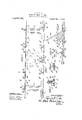
In th s zucompanyiug d airings whirh illustrate Certain enihodimui'ds of the inrnnl,il.m,----Figure 1 in a plan virw of an adjush able squarn illustrating: lho invenlion, showing the haso and two :uliustahle and r0- voraihlr angle mnmhcrs; l ig. .2 in a side or edge View oi. lho dnvioe :il'anm in Fig. 1; Fig". is a cross HQl'iiOh, enlarged, oi lhn ham? (ill M116 3--3 of Fig. l; l igl. lis, :1 c oss lion, enlarged, on line .1 ol" hig. :3 GllUW- ing ono of the iuljunliug; srrnwl-i l' igi 5 is a cross section, enlarged, on linn of l 'igg. and lligf. 6 a plan view of nuolher i nl'lll of adjuslal'iln angle lfltlillllftl.
The base oons'silzs of a llal liar of any dos'lrerl llaigth having a loi'igiludinah rl nlral slot for engaging); and mulling [he adjualin; and sliding devices of ihe anythmembers; This longiiudi' slotted base, as herein shown, is won '0 flat metal bars a, (a spaced apart to form the slot b hotwrnn thmn, and seminal to nan-h other by hridgn piwl-s or yokei; 1*, of which there may ho as many as are medndlo give lho base :Fiuflirilml' F=ll'Qll1'l-il and stillness; Said yolivn arn smeurnd lo the SilllS oi lho has a, (.2 and are howlull as silOWIl, as not lo oi'isirurtt the slot I). which is open and unobstructed from and to end. Two metal. angrln inonihnrs or .wlIlll'llS are ndjushihly and rvmorahly mounlrll on said basil, each having; a guiding arni (Z, overlying and slidnhly secured in the hasn. and an uprigid arm n disposed al right angina lo the arm (A The arm (l in prl'i'lerahly oi the snow width an tho has-1n upon Whirh. it nliilvs and is; orwi'idoil on iii: nndnr side with a loanilni'linally rxlnndiini; lon'n un, or l-l'll*i-; oi" ilfil'lgg'll if, which iii, Within and mining! 1hr lln; lili"; ol
nai ly l 538, lll'l 3.
i-lllii- 1) all: lua olnrl an lu nL shown: in Figs 3 -l and 5, nncl the tongues are similarly hovnll d, so that when the arnr-i (l are c amped on in the ham aw lwruinnf'lnr dosrrihell the how olrd surl'am-s-a nl' Lho longnirs nngzaggn the hernllnl bllllfiililll'-l oi lho slot, llini'oln; insuring lindd; kill and prnrnnling lhn i iaaihility oli any lalrral play or loowinrss helwnon lihn angglla llllllllllfl and ihn hnao. All. snicahlo inlla-vale on the under sido of tho momma f a 1n the luiada or studs calmnling ov er Elm margins of lho bars a, a al, each side of the rslol I, to hold lho angle inmnhfirs in sliding vngagoninnl, with lha hash. 'lhe angle nelm hnrs are hold in alijui'slml position by clam! ing nnunlmrn ronaialing' of studs 11, nxtcnl'ling through llioslol, b and the arms (2, having lawn-1 i engaging the margins of bars a, a at vilhvr side of the slot 7), and being screw lhrnadld at (heir upper vnds. Thumb arrows j are screwed on lo said studs in, and springs are inll-r oavd hvtwcrn the llunnb sari-airs j and the arms (Z. ll srrcwing lluunh srrvn' j down rd unlil illf springs In are fully (HlIIPIlISwl i lhn arm ri' may he posilivcl y and innnorahly clampnd in placr. By loosening lhr arrows; ilr.
hash. and will he hold in piano by friclionalnngagnmrul. \rilh greater or loss liruinesl-s acrorlling lo lhr expansive Force of the springs n'hirh Ina ill. rr gulalod hy the screws Hurh yielding lrivlional engagement will he sulliricnl lo hold tho llllifll nunnhrr against arcidvnlal dislmlguwnl. hul will also permit the user to slidu lho a uglc member to different positions, so lha when frequent Changes of adjuslnwnt are llqllil'tll for the. work in hand. lhvy may ill, n'mdn without manipulatinn' lhv srrrws laid angle nu uihcrs may hn wholly rmnovvd h sliding lluun length- \YiHL' out oi rngaggmnmil \vilh slot I), whereupon if duxired liufv may he reversed. right for left and vim: \llnn, and applied as shown in doth-d lines in Fig". 1, with the arms: (I (mending ouhwirdly inslvad of inwardly and tho angle arms; at lhv inner ends in the nun'lilicalion shown in Fig. 6 the lJllfSP is llu': Raine as, in lho olher figures of lhe drawings. 'lho angg lv uu-mhur however conslHlH ol lluloin m and a pivoted together by a Hlllll I \rhirh is similar to 12 and is provided wil'h :1 nul, t-Lilillllll' in j. Links 0, 0, each irolwl al one rod to om of tho lugs and iroml at lho olhvr 0nd in vavh othnrby .ud p, are provided to adjust the spread of the m at. The stud Works in asiot g and a thiunii screw 8 on stud p, is up the iinks and legs in adjusted osioion. The bar 9 is pivotaliy connected v,c i their pivotal point Z. At the end. each leg is a stud t and thumb screw u substantially like stu'd rt and screw j, hereinhei'ore described. The pivot 32 is in the form of a stud similar to h and as a thumb screw w, similar to y'. The
member consisting of the legs m and as may he adg'ustabiy secured to the base by Z one oi the studs t, as
shown in the drawings, or by securing both studs at the ends of? the legs to the base-with the p11 tai point 5 at the top. in either case the angle member constitutes with the base a hevei, the angie oif which may be varied as udy .escriued, iThus the device constitutes adjustable square or bevel, as de sired, suited to the great variety of uses to which such instruments are put in carpentering and building.
I claim:
A carpenters instrument comprising a straight base consisting of a pair of bars spaced apart to provide a slot therebetween, said slot being open and unobstructed from end to end, and said bars being secured to gether by a series of yokes, an angle member mounted on said bars and adJuStable length Wise thereof, and clamping means exten in" through said slot adapted to secure sai angle member in adjusted position.
Signed by me at Boston, Massachusetts this 23rd day of April, 1913.
- FRANK G. COLE.
Witnesses ROBERT CUSHMAN, CHARLES D. WOODBERRY.
Applications Claiming Priority (1)
| Application Number | Priority Date | Filing Date | Title |
|---|---|---|---|
| US1079110TA |
Publications (1)
| Publication Number | Publication Date |
|---|---|
| US1079110A true US1079110A (en) | 1913-11-18 |
Family
ID=3147344
Family Applications (1)
| Application Number | Title | Priority Date | Filing Date |
|---|---|---|---|
| US76394?13A Expired - Lifetime US1079110A (en) | Adjustable square and bevel. |
Country Status (1)
| Country | Link |
|---|---|
| US (1) | US1079110A (en) |
Cited By (3)
| Publication number | Priority date | Publication date | Assignee | Title |
|---|---|---|---|---|
| US2426780A (en) * | 1944-03-13 | 1947-09-02 | Harry F Malseed | Sliding cutoff gauge and measuring device for circular saws |
| US2881525A (en) * | 1953-09-14 | 1959-04-14 | John R Johnston | Combined saw guide and dividers |
| US7043849B1 (en) * | 2005-02-03 | 2006-05-16 | Delmar Laurence Leger | Multifunction caliper instrument for the arts |
-
0
- US US76394?13A patent/US1079110A/en not_active Expired - Lifetime
Cited By (3)
| Publication number | Priority date | Publication date | Assignee | Title |
|---|---|---|---|---|
| US2426780A (en) * | 1944-03-13 | 1947-09-02 | Harry F Malseed | Sliding cutoff gauge and measuring device for circular saws |
| US2881525A (en) * | 1953-09-14 | 1959-04-14 | John R Johnston | Combined saw guide and dividers |
| US7043849B1 (en) * | 2005-02-03 | 2006-05-16 | Delmar Laurence Leger | Multifunction caliper instrument for the arts |
Similar Documents
| Publication | Publication Date | Title |
|---|---|---|
| US1079110A (en) | Adjustable square and bevel. | |
| US1030073A (en) | Embroidery-hoop. | |
| US1519735A (en) | Switch-box bracket | |
| US1201342A (en) | Drafting instrument. | |
| US1416652A (en) | Device | |
| US766562A (en) | Combination-rule. | |
| US475390A (en) | Silas c | |
| US453385A (en) | Thomas j | |
| US1000133A (en) | Square and bevel. | |
| US997551A (en) | Compound instrument. | |
| US1085415A (en) | Compasses. | |
| US1061045A (en) | Rule attachment. | |
| US2484361A (en) | Drawing instrument | |
| US1242467A (en) | Geometrical instrument. | |
| US1223644A (en) | Rule. | |
| US994570A (en) | Combined protractor and t-square. | |
| US1436848A (en) | Dividers | |
| US1408800A (en) | Carpenter's square and bevel | |
| US1477210A (en) | Square | |
| US734149A (en) | Ruler. | |
| US682637A (en) | Combined rule and square. | |
| US1375649A (en) | Straightedge | |
| US743100A (en) | Carpenter's level and quadrant. | |
| US1211568A (en) | Scale. | |
| US204428A (en) | Improvement in try-square, bevel, and miter |