US10790932B2 - Padding bits for CSI report coding - Google Patents
Padding bits for CSI report coding Download PDFInfo
- Publication number
- US10790932B2 US10790932B2 US16/245,825 US201916245825A US10790932B2 US 10790932 B2 US10790932 B2 US 10790932B2 US 201916245825 A US201916245825 A US 201916245825A US 10790932 B2 US10790932 B2 US 10790932B2
- Authority
- US
- United States
- Prior art keywords
- csi
- bitwidth
- payload
- max
- maximum allowable
- Prior art date
- Legal status (The legal status is an assumption and is not a legal conclusion. Google has not performed a legal analysis and makes no representation as to the accuracy of the status listed.)
- Expired - Fee Related
Links
Images


Classifications
-
- H—ELECTRICITY
- H04—ELECTRIC COMMUNICATION TECHNIQUE
- H04L—TRANSMISSION OF DIGITAL INFORMATION, e.g. TELEGRAPHIC COMMUNICATION
- H04L1/00—Arrangements for detecting or preventing errors in the information received
- H04L1/004—Arrangements for detecting or preventing errors in the information received by using forward error control
- H04L1/0041—Arrangements at the transmitter end
- H04L1/0042—Encoding specially adapted to other signal generation operation, e.g. in order to reduce transmit distortions, jitter, or to improve signal shape
-
- H—ELECTRICITY
- H04—ELECTRIC COMMUNICATION TECHNIQUE
- H04L—TRANSMISSION OF DIGITAL INFORMATION, e.g. TELEGRAPHIC COMMUNICATION
- H04L1/00—Arrangements for detecting or preventing errors in the information received
- H04L1/0001—Systems modifying transmission characteristics according to link quality, e.g. power backoff
- H04L1/0023—Systems modifying transmission characteristics according to link quality, e.g. power backoff characterised by the signalling
- H04L1/0026—Transmission of channel quality indication
-
- H—ELECTRICITY
- H03—ELECTRONIC CIRCUITRY
- H03M—CODING; DECODING; CODE CONVERSION IN GENERAL
- H03M13/00—Coding, decoding or code conversion, for error detection or error correction; Coding theory basic assumptions; Coding bounds; Error probability evaluation methods; Channel models; Simulation or testing of codes
- H03M13/03—Error detection or forward error correction by redundancy in data representation, i.e. code words containing more digits than the source words
- H03M13/05—Error detection or forward error correction by redundancy in data representation, i.e. code words containing more digits than the source words using block codes, i.e. a predetermined number of check bits joined to a predetermined number of information bits
- H03M13/13—Linear codes
-
- H—ELECTRICITY
- H04—ELECTRIC COMMUNICATION TECHNIQUE
- H04B—TRANSMISSION
- H04B7/00—Radio transmission systems, i.e. using radiation field
- H04B7/02—Diversity systems; Multi-antenna system, i.e. transmission or reception using multiple antennas
- H04B7/04—Diversity systems; Multi-antenna system, i.e. transmission or reception using multiple antennas using two or more spaced independent antennas
- H04B7/0413—MIMO systems
- H04B7/0456—Selection of precoding matrices or codebooks, e.g. using matrices antenna weighting
- H04B7/046—Selection of precoding matrices or codebooks, e.g. using matrices antenna weighting taking physical layer constraints into account
- H04B7/0473—Selection of precoding matrices or codebooks, e.g. using matrices antenna weighting taking physical layer constraints into account taking constraints in layer or codeword to antenna mapping into account
-
- H—ELECTRICITY
- H04—ELECTRIC COMMUNICATION TECHNIQUE
- H04B—TRANSMISSION
- H04B7/00—Radio transmission systems, i.e. using radiation field
- H04B7/02—Diversity systems; Multi-antenna system, i.e. transmission or reception using multiple antennas
- H04B7/04—Diversity systems; Multi-antenna system, i.e. transmission or reception using multiple antennas using two or more spaced independent antennas
- H04B7/0413—MIMO systems
- H04B7/0456—Selection of precoding matrices or codebooks, e.g. using matrices antenna weighting
- H04B7/0486—Selection of precoding matrices or codebooks, e.g. using matrices antenna weighting taking channel rank into account
-
- H—ELECTRICITY
- H04—ELECTRIC COMMUNICATION TECHNIQUE
- H04B—TRANSMISSION
- H04B7/00—Radio transmission systems, i.e. using radiation field
- H04B7/02—Diversity systems; Multi-antenna system, i.e. transmission or reception using multiple antennas
- H04B7/04—Diversity systems; Multi-antenna system, i.e. transmission or reception using multiple antennas using two or more spaced independent antennas
- H04B7/06—Diversity systems; Multi-antenna system, i.e. transmission or reception using multiple antennas using two or more spaced independent antennas at the transmitting station
- H04B7/0613—Diversity systems; Multi-antenna system, i.e. transmission or reception using multiple antennas using two or more spaced independent antennas at the transmitting station using simultaneous transmission
- H04B7/0615—Diversity systems; Multi-antenna system, i.e. transmission or reception using multiple antennas using two or more spaced independent antennas at the transmitting station using simultaneous transmission of weighted versions of same signal
- H04B7/0619—Diversity systems; Multi-antenna system, i.e. transmission or reception using multiple antennas using two or more spaced independent antennas at the transmitting station using simultaneous transmission of weighted versions of same signal using feedback from receiving side
- H04B7/0621—Feedback content
- H04B7/0626—Channel coefficients, e.g. channel state information [CSI]
-
- H—ELECTRICITY
- H04—ELECTRIC COMMUNICATION TECHNIQUE
- H04B—TRANSMISSION
- H04B7/00—Radio transmission systems, i.e. using radiation field
- H04B7/02—Diversity systems; Multi-antenna system, i.e. transmission or reception using multiple antennas
- H04B7/04—Diversity systems; Multi-antenna system, i.e. transmission or reception using multiple antennas using two or more spaced independent antennas
- H04B7/06—Diversity systems; Multi-antenna system, i.e. transmission or reception using multiple antennas using two or more spaced independent antennas at the transmitting station
- H04B7/0613—Diversity systems; Multi-antenna system, i.e. transmission or reception using multiple antennas using two or more spaced independent antennas at the transmitting station using simultaneous transmission
- H04B7/0615—Diversity systems; Multi-antenna system, i.e. transmission or reception using multiple antennas using two or more spaced independent antennas at the transmitting station using simultaneous transmission of weighted versions of same signal
- H04B7/0619—Diversity systems; Multi-antenna system, i.e. transmission or reception using multiple antennas using two or more spaced independent antennas at the transmitting station using simultaneous transmission of weighted versions of same signal using feedback from receiving side
- H04B7/0621—Feedback content
- H04B7/063—Parameters other than those covered in groups H04B7/0623 - H04B7/0634, e.g. channel matrix rank or transmit mode selection
-
- H—ELECTRICITY
- H04—ELECTRIC COMMUNICATION TECHNIQUE
- H04B—TRANSMISSION
- H04B7/00—Radio transmission systems, i.e. using radiation field
- H04B7/02—Diversity systems; Multi-antenna system, i.e. transmission or reception using multiple antennas
- H04B7/04—Diversity systems; Multi-antenna system, i.e. transmission or reception using multiple antennas using two or more spaced independent antennas
- H04B7/06—Diversity systems; Multi-antenna system, i.e. transmission or reception using multiple antennas using two or more spaced independent antennas at the transmitting station
- H04B7/0613—Diversity systems; Multi-antenna system, i.e. transmission or reception using multiple antennas using two or more spaced independent antennas at the transmitting station using simultaneous transmission
- H04B7/0615—Diversity systems; Multi-antenna system, i.e. transmission or reception using multiple antennas using two or more spaced independent antennas at the transmitting station using simultaneous transmission of weighted versions of same signal
- H04B7/0619—Diversity systems; Multi-antenna system, i.e. transmission or reception using multiple antennas using two or more spaced independent antennas at the transmitting station using simultaneous transmission of weighted versions of same signal using feedback from receiving side
- H04B7/0621—Feedback content
- H04B7/0632—Channel quality parameters, e.g. channel quality indicator [CQI]
-
- H—ELECTRICITY
- H04—ELECTRIC COMMUNICATION TECHNIQUE
- H04B—TRANSMISSION
- H04B7/00—Radio transmission systems, i.e. using radiation field
- H04B7/02—Diversity systems; Multi-antenna system, i.e. transmission or reception using multiple antennas
- H04B7/04—Diversity systems; Multi-antenna system, i.e. transmission or reception using multiple antennas using two or more spaced independent antennas
- H04B7/06—Diversity systems; Multi-antenna system, i.e. transmission or reception using multiple antennas using two or more spaced independent antennas at the transmitting station
- H04B7/0613—Diversity systems; Multi-antenna system, i.e. transmission or reception using multiple antennas using two or more spaced independent antennas at the transmitting station using simultaneous transmission
- H04B7/0615—Diversity systems; Multi-antenna system, i.e. transmission or reception using multiple antennas using two or more spaced independent antennas at the transmitting station using simultaneous transmission of weighted versions of same signal
- H04B7/0619—Diversity systems; Multi-antenna system, i.e. transmission or reception using multiple antennas using two or more spaced independent antennas at the transmitting station using simultaneous transmission of weighted versions of same signal using feedback from receiving side
- H04B7/0636—Feedback format
- H04B7/0639—Using selective indices, e.g. of a codebook, e.g. pre-distortion matrix index [PMI] or for beam selection
-
- H—ELECTRICITY
- H04—ELECTRIC COMMUNICATION TECHNIQUE
- H04L—TRANSMISSION OF DIGITAL INFORMATION, e.g. TELEGRAPHIC COMMUNICATION
- H04L1/00—Arrangements for detecting or preventing errors in the information received
- H04L1/0001—Systems modifying transmission characteristics according to link quality, e.g. power backoff
- H04L1/0006—Systems modifying transmission characteristics according to link quality, e.g. power backoff by adapting the transmission format
- H04L1/0007—Systems modifying transmission characteristics according to link quality, e.g. power backoff by adapting the transmission format by modifying the frame length
- H04L1/0008—Systems modifying transmission characteristics according to link quality, e.g. power backoff by adapting the transmission format by modifying the frame length by supplementing frame payload, e.g. with padding bits
-
- H—ELECTRICITY
- H04—ELECTRIC COMMUNICATION TECHNIQUE
- H04L—TRANSMISSION OF DIGITAL INFORMATION, e.g. TELEGRAPHIC COMMUNICATION
- H04L1/00—Arrangements for detecting or preventing errors in the information received
- H04L1/0001—Systems modifying transmission characteristics according to link quality, e.g. power backoff
- H04L1/0023—Systems modifying transmission characteristics according to link quality, e.g. power backoff characterised by the signalling
- H04L1/0028—Formatting
- H04L1/0029—Reduction of the amount of signalling, e.g. retention of useful signalling or differential signalling
-
- H—ELECTRICITY
- H04—ELECTRIC COMMUNICATION TECHNIQUE
- H04L—TRANSMISSION OF DIGITAL INFORMATION, e.g. TELEGRAPHIC COMMUNICATION
- H04L1/00—Arrangements for detecting or preventing errors in the information received
- H04L1/0001—Systems modifying transmission characteristics according to link quality, e.g. power backoff
- H04L1/0023—Systems modifying transmission characteristics according to link quality, e.g. power backoff characterised by the signalling
- H04L1/0028—Formatting
- H04L1/0031—Multiple signaling transmission
-
- H—ELECTRICITY
- H04—ELECTRIC COMMUNICATION TECHNIQUE
- H04L—TRANSMISSION OF DIGITAL INFORMATION, e.g. TELEGRAPHIC COMMUNICATION
- H04L1/00—Arrangements for detecting or preventing errors in the information received
- H04L1/004—Arrangements for detecting or preventing errors in the information received by using forward error control
- H04L1/0056—Systems characterized by the type of code used
- H04L1/0057—Block codes
-
- H—ELECTRICITY
- H04—ELECTRIC COMMUNICATION TECHNIQUE
- H04L—TRANSMISSION OF DIGITAL INFORMATION, e.g. TELEGRAPHIC COMMUNICATION
- H04L1/00—Arrangements for detecting or preventing errors in the information received
- H04L1/004—Arrangements for detecting or preventing errors in the information received by using forward error control
- H04L1/0072—Error control for data other than payload data, e.g. control data
-
- H—ELECTRICITY
- H04—ELECTRIC COMMUNICATION TECHNIQUE
- H04W—WIRELESS COMMUNICATION NETWORKS
- H04W28/00—Network traffic management; Network resource management
- H04W28/02—Traffic management, e.g. flow control or congestion control
- H04W28/06—Optimizing the usage of the radio link, e.g. header compression, information sizing, discarding information
-
- H04W72/0413—
-
- H—ELECTRICITY
- H04—ELECTRIC COMMUNICATION TECHNIQUE
- H04W—WIRELESS COMMUNICATION NETWORKS
- H04W72/00—Local resource management
- H04W72/20—Control channels or signalling for resource management
- H04W72/21—Control channels or signalling for resource management in the uplink direction of a wireless link, i.e. towards the network
Definitions
- Embodiments described herein relate generally to wireless networks and communications systems. Some embodiments relate to cellular communication networks including 3GPP (Third Generation Partnership Project) networks, 3GPP LTE (Long Term Evolution) networks, 3GPP LTE-A (LTE Advanced), and 3GPP fifth generation (5G) or new radio (NR) networks, although the scope of the embodiments is not limited in this respect.
- 3GPP Three Generation Partnership Project
- 3GPP LTE Long Term Evolution
- 3GPP LTE-A Long Term Evolution Advanced
- NR new radio
- a mobile terminal In Long Term Evolution (LTE) and next generation new radio (NR) systems, a mobile terminal (referred to as a User Equipment or UE) connects to the cellular network via a base station (referred to as an evolved Node B or eNB or as a next generation Node B or gNB).
- a base station referred to as an evolved Node B or eNB or as a next generation Node B or gNB.
- CSI channel state information
- FIG. 1 is illustrates an example UE and a base station (BS) such as an eNB or gNB according to some embodiments.
- BS base station
- FIG. 2 illustrates alternative locations for padding bits.
- FIG. 3 illustrates PMI bitwidths for different parameter configurations.
- FIG. 4 illustrates an example table of LI and CQI bitwidths for different parameter configurations.
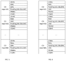
- FIGS. 5 through 8 illustrate alternatives for encoding multiple CSI payloads for multiple CSI reports into a single codeword.
- FIG. 1 illustrates an example of the components of a UE 1400 and a base station (e.g., eNB or gNB) 1300 .
- the BS 1300 includes processing circuitry 1301 connected to a radio transceiver 1302 for providing an air interface.
- the UE 1400 includes processing circuitry 1401 connected to a radio transceiver 1402 for providing an air interface over the wireless medium.
- Each of the transceivers in the devices is connected to antennas 1055 .
- the antennas 1055 of the devices form antenna arrays whose directionality may be controlled by the processing circuitry.
- the memory and processing circuitries of the UE and/or BS may be configured to perform the functions and implement the schemes of the various embodiments described herein.
- LTE and NR provides reference signals that may be used by a UE to obtain downlink channel state information (CSI) for a transmitting cell, referred to as channel state information reference signals (CSI-RSs).
- CSI-RSs downlink channel state information
- the UE may then feedback the CSI thus obtained to the serving cell in the form of a CSI report.
- CSI-RS are transmitted using particular time-frequency resource element (REs) of an orthogonal frequency division multiple access (OFDMA) transmission scheme over the physical downlink shared channel (PDSCH) with a configurable periodicity and spanning the entire transmit band.
- OFDMA orthogonal frequency division multiple access
- Multiple sets of CSI-RSs may be transmitted by a cell with each set corresponding to a different antenna port.
- a UE may use the CSI-RSs to estimate the channel and produce a CSI report that is fed back to the serving cell either multiplexed with data over the PDSCH or via the physical uplink control channel (PUCCH).
- the CSI report is encoded with a forward error correction (FEC) such as a polar code and sent over the PUCCH.
- FEC forward error correction
- a channel state information report may include a channel quality indicator (CQI) that represents the highest modulation and coding scheme that could be used in the channel without exceeding a specified error rate, a rank indicator (RI) that represents the number of spatial multiplexing layers that could be used in the channel, a precoding matrix indicator (PMI) that represents a preferred antenna weighting scheme for transmitting to the UE, a sub-band (SB) indicator that represents the subcarriers preferred by the UE, and a CSI-RS resource indicator (CRI) to indicate a preferred antenna beam.
- CQI channel quality indicator
- RI rank indicator
- PMI precoding matrix indicator
- SB sub-band
- CRI CSI-RS resource indicator
- the eNB In order to configure a UE to receive and process reference signals and to provide appropriate feedback in the form of CSI reports, the eNB signals the UE using the radio resource control (RRC) protocol to send what are referred to herein as higher layer parameters.
- RRC radio resource control
- An RRC message that transmits CSI-RS configuration information from an eNB to a UE originates in the RRC layer of the eNB and, after traversing the protocol layers, is then transmitted to the UE via the PDSCH. The UE then processes the message at its corresponding RRC layer.
- CRI/RI In LTE, due to dependency between CSI components, coding of CRI/RI and PMI/CQI using a forward error correction (FEC) code is carried out independently from each other.
- FEC forward error correction
- the bitwidth of CRI/RI is typically known by the base station based on the higher layer configuration and/or derived from CSI-RS antenna port configuration and reported UE capability. Based on the decoded CRI/RI, the UE determines the payload size of PMI/CQI report. In particular, for LTE. if the reported RI is 1, the single CQI report should be assumed in the UCI, otherwise there are two CQI reports. In addition, the bitwidth of the PMI report also depends on the reported RI.
- the LTE approach supports separate coding of CRI/RI and CQI/PMI in two codewords, where payload of CQI/PMI report is decided after decoding of the CRI/RI codeword.
- Separate coding of CSI components is less efficient than joint one from channel coding perspective.
- the dependency of the PMI/CQI payload on the current RI/CRI value may lead to payload size ambiguity on the decoder side. It is possible to avoid this by adding a certain amount of padding bits to the CSI payload.
- the number of padding bits may be made to depend on the current RI/CRI value and higher layer configuration. Described below are methods and apparatus to determine the padding bits quantity for joint CSI coding.
- the padding bits equalize payload size for different CRI/RI cases and allow encoding of all parts of CSI in one codeword without payload ambiguity.
- padding bits are appended to a CSI payload of size A CSI to make a result bit sequence, which is then passed to encoder input.
- the padding bits may be zeroes or any other fixed values.
- the amount of padding bits should be such that the result sequence is of size A max CSI (where A max CSI is the maximum possible CSI payload over all CRI/RI values with the current higher-layer MIMO configuration).
- the padding bits can be placed in continuous or non-continuous block at different positions inside CSI payload as illustrated in FIG. 2 which shows three alternatives labeled as:
- Alt3 is preferable since it gives some additional coding gain under sequential decoding, e.g., polar SCL decoding.
- the gain obtained can be described as follows.
- CRI/RI is decoded after all padding bits. Given this, it is not possible to determine the amount of padding bits prior to their decoding. They have to be decoded as information bits that leads to worst-case coding gain (same as with maximum payload A max CSI in current MIMO configuration).
- Alt2 CRI/RI is decoded before the padding bits. This allows a decoder to treat padding bits as frozen bits, which could increase the coding gain. However, this increase is negligible since these frozen appear after all the info bits are already decoded.
- Alt3 provides the ability to decode CRI/RI before the padding bits, compute their quantity, treat padding bits as frozen and then decode other part of CSI payload. Implementation of such advanced decoding approach may provide significant coding gain.
- the components of the CSI payload are ordered as follows: CRI, RI, LI, padding bits, PMI, and CQI.
- the amount of padding bits that is needed to be added to the CSI payload A CSI is specified depending on current CRI/RI value and higher layer configuration.
- B RI ⁇ RIi
- a number of possible rank values allowed by higher layer parameter RI_Restriction n RI all
- the maximum CSI payload is defined as a maximum payload possible under current RI_Restriction and ResourseSetBitmap parameters as configured by higher layers:
- a LI , A PMI and A CQI are usually defined in tables with each row corresponding to some combination of RI value and higher layer parameters. Therefore A max LI , A max PMI and A max CQI can be found as a maximum over the rows corresponding to the allowed rank values set B RI and current higher layer configuration as shown in FIG. 3 .
- LI and CQI maximum sizes can be found as the maximums over the table rows corresponding to the allowed rank values set B RI .
- the total padding bits quantity may then be defined as:
- a padding A RI + A CRI + max RI ⁇ B RI ⁇ ( A LI ) + max RI ⁇ B RI N 1 , N 2 ⁇ ( ⁇ i 1 , 1 , i 1 , 2 ⁇ + ⁇ i 1 , 3 ⁇ + ⁇ i 2 ⁇ ) + max RI ⁇ B RI ⁇ ( A CQI ) - A CSI
- the maximum CSI payload is defined as a maximum CSI payload possible in the standard:
- a max PMI max N 1 , ⁇ N 2 ⁇ ( ⁇ i 1 , 1 , i 1 , 2 ⁇ + ⁇ i 1 , 3 ⁇ + ⁇ i 2 ⁇ ) , e . g . ⁇ ⁇ log 2 ⁇ ( N 1 ⁇ O 1 ⁇ N 2 ⁇ O 2 ) ⁇ + 3 ⁇
- a max CQI max ⁇ ( A CQI ) , e . g . ⁇ 8
- the total padding bits quantity may then be defined as:
- a base station may request a UE to transmit several CSI reports.
- multiple CSI payloads representing multiple CSI reports are encoded as described above. Such methods allow encoding of these multiple CSI reports into one codeword which is more efficient than separate coding.
- FIG. 5 illustrates one alternative for encoding the multiple CSI payloads for CSI reports #1 through #n successively in a single codeword.
- the multiple CSI payloads representing the multiple CSI reports ordered sequentially to form a single encoder input bit sequence for encoding into the single codeword.
- the order of the components for each CSI payload is: CRI, RI, LI, padding bits, PMI, and CQI.
- FIG. 6 illustrates another alternative for encoding the multiple CSI payloads for CSI reports #1 through #n successively in a single codeword in which the order of the components for each CSI payload is: CRI, RI, padding bits, LI, PMI, and CQI.
- FIGS. 7 and 8 illustrate other alternatives for encoding the multiple CSI payloads for CSI reports #1 through #n in a single codeword in which the components of the CSI payloads are grouped into blocks that are successively encoded.
- the order of the blocks is: CRI block, RI block, LI block, padding bits block, PMI block, and CQI block.
- the order of the blocks is: CRI block, RI block, padding bits block, LI block, PMI block, and CQI block.
- the padding bits quantity may be defined as:
- the terms “a” or “an” are used, as is common in patent documents, to include one or more than one, independent of any other instances or usages of “at least one” or “one or more.”
- the term “or” is used to refer to a nonexclusive or, such that “A or B” includes “A but not B,” “B but not A,” and “A and B,” unless otherwise indicated.
- the embodiments as described above may be implemented in various hardware configurations that may include a processor for executing instructions that perform the techniques described. Such instructions may be contained in a machine-readable medium such as a suitable storage medium or a memory or other processor-executable medium.
- the embodiments as described herein may be implemented in a number of environments such as part of a wireless local area network (WLAN), 3rd Generation Partnership Project (3GPP) Universal Terrestrial Radio Access Network (UTRAN), or Long-Term-Evolution (LTE) or a Long-Term-Evolution (LTE) communication system, although the scope of the disclosure is not limited in this respect.
- WLAN wireless local area network
- 3GPP 3rd Generation Partnership Project
- UTRAN Universal Terrestrial Radio Access Network
- LTE Long-Term-Evolution
- LTE Long-Term-Evolution
- LTE Long-Term-Evolution
- LTE Long-Term-Evolution
- Antennas referred to herein may comprise one or more directional or omnidirectional antennas, including, for example, dipole antennas, monopole antennas, patch antennas, loop antennas, microstrip antennas or other types of antennas suitable for transmission of RF signals.
- a single antenna with multiple apertures may be used instead of two or more antennas.
- each aperture may be considered a separate antenna.
- antennas may be effectively separated to take advantage of spatial diversity and the different channel characteristics that may result between each of antennas and the antennas of a transmitting station.
- antennas may be separated by up to 1/10 of a wavelength or more.
- a receiver as described herein may be configured to receive signals in accordance with specific communication standards, such as the Institute of Electrical and Electronics Engineers (IEEE) standards including IEEE 802.11-2007 and/or 802.11(n) standards and/or proposed specifications for WLANs, although the scope of the disclosure is not limited in this respect as they may also be suitable to transmit and/or receive communications in accordance with other techniques and standards.
- IEEE Institute of Electrical and Electronics Engineers
- the receiver may be configured to receive signals in accordance with the IEEE 802.16-2004, the IEEE 802.16(e) and/or IEEE 802.16(m) standards for wireless metropolitan area networks (WMANs) including variations and evolutions thereof, although the scope of the disclosure is not limited in this respect as they may also be suitable to transmit and/or receive communications in accordance with other techniques and standards.
- the receiver may be configured to receive signals in accordance with the Universal Terrestrial Radio Access Network (UTRAN) LTE communication standards.
- UTRAN Universal Terrestrial Radio Access Network
- IEEE 802.11 and IEEE 802.16 standards please refer to “IEEE Standards for Information Technology—Telecommunications and Information Exchange between Systems”—Local Area Networks—Specific Requirements—Part 11 “Wireless LAN Medium Access Control (MAC) and Physical Layer (PHY), ISO/IEC 8802-11: 1999”, and Metropolitan Area Networks—Specific Requirements—Part 16: “Air Interface for Fixed Broadband Wireless Access Systems,” May 2005 and related amendments/versions.
- 3GPP 3rd Generation Partnership Project
Landscapes
- Engineering & Computer Science (AREA)
- Computer Networks & Wireless Communication (AREA)
- Signal Processing (AREA)
- Quality & Reliability (AREA)
- Physics & Mathematics (AREA)
- Mathematical Physics (AREA)
- Probability & Statistics with Applications (AREA)
- Theoretical Computer Science (AREA)
- Mobile Radio Communication Systems (AREA)
Abstract
Description
-
- Alt1—padding bits are placed at the start of result sequence
- Alt2—padding bits are placed at the end of result sequence
- Alt3—padding bits are placed in the middle of result sequence
A padding =A max CSI −A CSI
where Amax CSI=Amax RI+Amax CRI+Amax LI+Amax PMI+Amax CQI.
| BRI = {RIi|RI_Restriction & 2i = 1} | a set of possible rank values allowed by |
| higher layer parameter RI_Restriction | |
| BRI all = {1 ... RImax} | a set of all possible rank values defined |
| in the standard | |
| nRI = |BRI| | a number of possible rank values allowed |
| by higher layer parameter RI_Restriction | |
| nRI all = |BRI all| = RImax | a number of possible rank values in the |
| standard | |
| S | a number of different CSI-RS resource |
| sets available according to higher layer | |
| parameter ResourceConfig | |
| BCRI, s, 0 ≤ s < S | CSI-RS resource set s used for current |
| CSI report according to higher layer | |
| parameter ResourseSetBitmap | |
|
|
is a set of all possible CSI-RS resources defined in the standard |
| Ks CSI-RS = |BCRI, s|, 0 ≤ s < S | a number of CSI-RS resources in the |
| resource set s | |
| Kmax CSI-RS = max(|BCRI, all|) | a maximum number of CSI-RS resources |
| in the resource set defined in the standard | |
| N1, N2 | numbers of antenna ports on BS divided by |
| 2 over 2 dimensions | |
| O1, O2 | oversampling values divided by 2 over 2 |
| dimensions | |
| |i1,1, i1,2|, |i1,3|, |i2| | bitwidths of PMI parts (PM indices) |
| PCSI-RS = 2·N1·N2 | a number of CSI-RS ports |
Bitwidths ALI, APMI and ACQI are usually defined in tables with each row corresponding to some combination of RI value and higher layer parameters. Therefore Amax LI, Amax PMI and Amax CQI can be found as a maximum over the rows corresponding to the allowed rank values set BRI and current higher layer configuration as shown in
Similarly, LI and CQI maximum sizes can be found as the maximums over the table rows corresponding to the allowed rank values set BRI.
In another embodiment, the maximum CSI payload is defined as a maximum CSI payload possible in the standard:
The total padding bits quantity may then be defined as:
A padding #i =A max CSI #i −A CSI #i
Claims (20)
Priority Applications (2)
| Application Number | Priority Date | Filing Date | Title |
|---|---|---|---|
| US16/245,825 US10790932B2 (en) | 2018-01-12 | 2019-01-11 | Padding bits for CSI report coding |
| US16/986,616 US20200382239A1 (en) | 2018-01-12 | 2020-08-06 | Padding bits for csi report coding |
Applications Claiming Priority (2)
| Application Number | Priority Date | Filing Date | Title |
|---|---|---|---|
| US201862617030P | 2018-01-12 | 2018-01-12 | |
| US16/245,825 US10790932B2 (en) | 2018-01-12 | 2019-01-11 | Padding bits for CSI report coding |
Related Child Applications (1)
| Application Number | Title | Priority Date | Filing Date |
|---|---|---|---|
| US16/986,616 Continuation US20200382239A1 (en) | 2018-01-12 | 2020-08-06 | Padding bits for csi report coding |
Publications (2)
| Publication Number | Publication Date |
|---|---|
| US20190149266A1 US20190149266A1 (en) | 2019-05-16 |
| US10790932B2 true US10790932B2 (en) | 2020-09-29 |
Family
ID=66432509
Family Applications (2)
| Application Number | Title | Priority Date | Filing Date |
|---|---|---|---|
| US16/245,825 Expired - Fee Related US10790932B2 (en) | 2018-01-12 | 2019-01-11 | Padding bits for CSI report coding |
| US16/986,616 Abandoned US20200382239A1 (en) | 2018-01-12 | 2020-08-06 | Padding bits for csi report coding |
Family Applications After (1)
| Application Number | Title | Priority Date | Filing Date |
|---|---|---|---|
| US16/986,616 Abandoned US20200382239A1 (en) | 2018-01-12 | 2020-08-06 | Padding bits for csi report coding |
Country Status (1)
| Country | Link |
|---|---|
| US (2) | US10790932B2 (en) |
Families Citing this family (5)
| Publication number | Priority date | Publication date | Assignee | Title |
|---|---|---|---|---|
| US11147065B2 (en) * | 2018-01-22 | 2021-10-12 | Qualcomm Incorporated | Feedback bit reservation for uplink control piggybacking |
| US11387880B2 (en) * | 2020-02-28 | 2022-07-12 | Qualcomm Incorporated | Channel state information feedback using channel compression and reconstruction |
| CN115706612A (en) * | 2021-08-04 | 2023-02-17 | 中兴通讯股份有限公司 | Feedback method, receiving method, terminal, base station and medium of channel state information |
| EP4254900B1 (en) * | 2022-03-28 | 2024-07-24 | Deutsche Telekom AG | Multipath receiver and processing of 3gpp atsss on a multipath receiver |
| US12468947B2 (en) | 2022-07-25 | 2025-11-11 | International Business Machines Corporation | Stickification using anywhere padding to accelerate data manipulation |
Citations (3)
| Publication number | Priority date | Publication date | Assignee | Title |
|---|---|---|---|---|
| US20150304674A1 (en) * | 2013-10-25 | 2015-10-22 | Mediatek Inc. | Method and apparatus for improving visual quality by using neighboring pixel information in flatness check and/or applying smooth function to quantization parameters/pixel values |
| US20180083666A1 (en) * | 2016-09-21 | 2018-03-22 | Huawei Technologies Co., Ltd. | Methods for multiple access transmission |
| US20190068268A1 (en) * | 2017-10-26 | 2019-02-28 | Yushu Zhang | Channel state information report for phase tracking reference signal port selection |
-
2019
- 2019-01-11 US US16/245,825 patent/US10790932B2/en not_active Expired - Fee Related
-
2020
- 2020-08-06 US US16/986,616 patent/US20200382239A1/en not_active Abandoned
Patent Citations (3)
| Publication number | Priority date | Publication date | Assignee | Title |
|---|---|---|---|---|
| US20150304674A1 (en) * | 2013-10-25 | 2015-10-22 | Mediatek Inc. | Method and apparatus for improving visual quality by using neighboring pixel information in flatness check and/or applying smooth function to quantization parameters/pixel values |
| US20180083666A1 (en) * | 2016-09-21 | 2018-03-22 | Huawei Technologies Co., Ltd. | Methods for multiple access transmission |
| US20190068268A1 (en) * | 2017-10-26 | 2019-02-28 | Yushu Zhang | Channel state information report for phase tracking reference signal port selection |
Also Published As
| Publication number | Publication date |
|---|---|
| US20190149266A1 (en) | 2019-05-16 |
| US20200382239A1 (en) | 2020-12-03 |
Similar Documents
| Publication | Publication Date | Title |
|---|---|---|
| EP3874662B1 (en) | Csi feedback for data transmission over multiple transmission points | |
| US11411629B2 (en) | Method for feeding back channel state information in wireless communication system and apparatus therefor | |
| US10812164B2 (en) | Method for reporting channel state information in wireless communication system and apparatus therefor | |
| KR102348750B1 (en) | Apparatus and method for coordinating multi-point transmission in an improved wireless system | |
| US10158411B2 (en) | Method and apparatus for transmitting channel state information in wireless communication system | |
| US9660780B2 (en) | Method for feeding back channel state information in wireless communication system and apparatus therefor | |
| US10790932B2 (en) | Padding bits for CSI report coding | |
| US9357419B2 (en) | Method for reporting channel state information in wireless communication system and apparatus for same | |
| US8737504B2 (en) | Method and system for feedback of channel information | |
| US20190109626A1 (en) | Method and apparatus for reporting channel state information in a wireless communication system | |
| CN115956350A (en) | Method and apparatus for enhanced CSI reporting on multiple downlink resources | |
| EP2661000B1 (en) | Method for reporting channel state information in a wireless communication system, and apparatus therefor | |
| US20120218968A1 (en) | Method for transmitting channel quality information, and apparatus for same | |
| CN104604173A (en) | Method for providing feedback of channel state information in wireless communication system and apparatus for same | |
| EP3579447B1 (en) | Method for periodically transmitting uplink control information in wireless communication system and apparatus for same | |
| JP2011518489A (en) | Transmission / reception method of downlink control information | |
| CN104170276A (en) | Method for reporting channel state information in wireless communication system, and apparatus therefor | |
| US12199723B2 (en) | Channel state information (CSI) omission procedure for rel. 16 type II CSI | |
| CN102823152A (en) | Data transmission method and device in multiple-input multiple-output communication system | |
| KR101208561B1 (en) | Method of efficient Multi-BaseStation MIMO operation in a Broadband Wireless Access System | |
| US20150327247A1 (en) | Channel quality indication for fallback transmission mode over new carrier type | |
| WO2018175727A1 (en) | Method for feedback of correlation of beams in wireless communication system and user equipment | |
| EP3672317B1 (en) | Method for channel measurement | |
| KR102045621B1 (en) | Method and apparatus for operating antenna subset in next generation mobile communication network |
Legal Events
| Date | Code | Title | Description |
|---|---|---|---|
| FEPP | Fee payment procedure |
Free format text: ENTITY STATUS SET TO UNDISCOUNTED (ORIGINAL EVENT CODE: BIG.); ENTITY STATUS OF PATENT OWNER: LARGE ENTITY |
|
| STPP | Information on status: patent application and granting procedure in general |
Free format text: DOCKETED NEW CASE - READY FOR EXAMINATION |
|
| AS | Assignment |
Owner name: INTEL CORPORATION, CALIFORNIA Free format text: ASSIGNMENT OF ASSIGNORS INTEREST;ASSIGNORS:DIKAREV, DMITRY;SERGEEV, VICTOR;NIMBALKER, AJIT;AND OTHERS;SIGNING DATES FROM 20190204 TO 20190218;REEL/FRAME:049462/0588 |
|
| AS | Assignment |
Owner name: APPLE INC., CALIFORNIA Free format text: ASSIGNMENT OF ASSIGNORS INTEREST;ASSIGNOR:INTEL CORPORATION;REEL/FRAME:052916/0308 Effective date: 20191130 |
|
| STPP | Information on status: patent application and granting procedure in general |
Free format text: NOTICE OF ALLOWANCE MAILED -- APPLICATION RECEIVED IN OFFICE OF PUBLICATIONS |
|
| STPP | Information on status: patent application and granting procedure in general |
Free format text: AWAITING TC RESP., ISSUE FEE NOT PAID |
|
| STPP | Information on status: patent application and granting procedure in general |
Free format text: AWAITING TC RESP, ISSUE FEE PAYMENT VERIFIED |
|
| STCF | Information on status: patent grant |
Free format text: PATENTED CASE |
|
| FEPP | Fee payment procedure |
Free format text: MAINTENANCE FEE REMINDER MAILED (ORIGINAL EVENT CODE: REM.); ENTITY STATUS OF PATENT OWNER: LARGE ENTITY |
|
| LAPS | Lapse for failure to pay maintenance fees |
Free format text: PATENT EXPIRED FOR FAILURE TO PAY MAINTENANCE FEES (ORIGINAL EVENT CODE: EXP.); ENTITY STATUS OF PATENT OWNER: LARGE ENTITY |
|
| STCH | Information on status: patent discontinuation |
Free format text: PATENT EXPIRED DUE TO NONPAYMENT OF MAINTENANCE FEES UNDER 37 CFR 1.362 |
|
| FP | Lapsed due to failure to pay maintenance fee |
Effective date: 20240929 |