US10790687B2 - Power supply control unit, controlling module, controlling device and controlling method of the same - Google Patents
Power supply control unit, controlling module, controlling device and controlling method of the same Download PDFInfo
- Publication number
- US10790687B2 US10790687B2 US15/586,309 US201715586309A US10790687B2 US 10790687 B2 US10790687 B2 US 10790687B2 US 201715586309 A US201715586309 A US 201715586309A US 10790687 B2 US10790687 B2 US 10790687B2
- Authority
- US
- United States
- Prior art keywords
- resistance
- power
- value
- power supply
- power source
- Prior art date
- Legal status (The legal status is an assumption and is not a legal conclusion. Google has not performed a legal analysis and makes no representation as to the accuracy of the status listed.)
- Active, expires
Links
- 238000000034 method Methods 0.000 title claims description 14
- 230000000052 comparative effect Effects 0.000 description 7
- 238000010586 diagram Methods 0.000 description 2
- 238000004519 manufacturing process Methods 0.000 description 2
Images


Classifications
-
- H—ELECTRICITY
- H02—GENERATION; CONVERSION OR DISTRIBUTION OF ELECTRIC POWER
- H02J—CIRCUIT ARRANGEMENTS OR SYSTEMS FOR SUPPLYING OR DISTRIBUTING ELECTRIC POWER; SYSTEMS FOR STORING ELECTRIC ENERGY
- H02J7/00—Circuit arrangements for charging or depolarising batteries or for supplying loads from batteries
- H02J7/0013—Circuit arrangements for charging or depolarising batteries or for supplying loads from batteries acting upon several batteries simultaneously or sequentially
-
- G—PHYSICS
- G08—SIGNALLING
- G08C—TRANSMISSION SYSTEMS FOR MEASURED VALUES, CONTROL OR SIMILAR SIGNALS
- G08C19/00—Electric signal transmission systems
- G08C19/02—Electric signal transmission systems in which the signal transmitted is magnitude of current or voltage
-
- H02J7/0021—
-
- H02J7/0026—
-
- H—ELECTRICITY
- H02—GENERATION; CONVERSION OR DISTRIBUTION OF ELECTRIC POWER
- H02J—CIRCUIT ARRANGEMENTS OR SYSTEMS FOR SUPPLYING OR DISTRIBUTING ELECTRIC POWER; SYSTEMS FOR STORING ELECTRIC ENERGY
- H02J7/00—Circuit arrangements for charging or depolarising batteries or for supplying loads from batteries
- H02J7/0047—Circuit arrangements for charging or depolarising batteries or for supplying loads from batteries with monitoring or indicating devices or circuits
-
- H02J7/0077—
-
- H—ELECTRICITY
- H02—GENERATION; CONVERSION OR DISTRIBUTION OF ELECTRIC POWER
- H02J—CIRCUIT ARRANGEMENTS OR SYSTEMS FOR SUPPLYING OR DISTRIBUTING ELECTRIC POWER; SYSTEMS FOR STORING ELECTRIC ENERGY
- H02J2207/00—Indexing scheme relating to details of circuit arrangements for charging or depolarising batteries or for supplying loads from batteries
- H02J2207/20—Charging or discharging characterised by the power electronics converter
-
- H—ELECTRICITY
- H02—GENERATION; CONVERSION OR DISTRIBUTION OF ELECTRIC POWER
- H02J—CIRCUIT ARRANGEMENTS OR SYSTEMS FOR SUPPLYING OR DISTRIBUTING ELECTRIC POWER; SYSTEMS FOR STORING ELECTRIC ENERGY
- H02J7/00—Circuit arrangements for charging or depolarising batteries or for supplying loads from batteries
-
- H02J7/0027—
-
- H—ELECTRICITY
- H02—GENERATION; CONVERSION OR DISTRIBUTION OF ELECTRIC POWER
- H02M—APPARATUS FOR CONVERSION BETWEEN AC AND AC, BETWEEN AC AND DC, OR BETWEEN DC AND DC, AND FOR USE WITH MAINS OR SIMILAR POWER SUPPLY SYSTEMS; CONVERSION OF DC OR AC INPUT POWER INTO SURGE OUTPUT POWER; CONTROL OR REGULATION THEREOF
- H02M1/00—Details of apparatus for conversion
- H02M1/0003—Details of control, feedback or regulation circuits
-
- H—ELECTRICITY
- H02—GENERATION; CONVERSION OR DISTRIBUTION OF ELECTRIC POWER
- H02M—APPARATUS FOR CONVERSION BETWEEN AC AND AC, BETWEEN AC AND DC, OR BETWEEN DC AND DC, AND FOR USE WITH MAINS OR SIMILAR POWER SUPPLY SYSTEMS; CONVERSION OF DC OR AC INPUT POWER INTO SURGE OUTPUT POWER; CONTROL OR REGULATION THEREOF
- H02M1/00—Details of apparatus for conversion
- H02M1/0067—Converter structures employing plural converter units, other than for parallel operation of the units on a single load
- H02M1/008—Plural converter units for generating at two or more independent and non-parallel outputs, e.g. systems with plural point of load switching regulators
-
- H—ELECTRICITY
- H02—GENERATION; CONVERSION OR DISTRIBUTION OF ELECTRIC POWER
- H02M—APPARATUS FOR CONVERSION BETWEEN AC AND AC, BETWEEN AC AND DC, OR BETWEEN DC AND DC, AND FOR USE WITH MAINS OR SIMILAR POWER SUPPLY SYSTEMS; CONVERSION OF DC OR AC INPUT POWER INTO SURGE OUTPUT POWER; CONTROL OR REGULATION THEREOF
- H02M1/00—Details of apparatus for conversion
- H02M1/0083—Converters characterised by their input or output configuration
- H02M1/009—Converters characterised by their input or output configuration having two or more independently controlled outputs
-
- H02M2001/008—
Definitions
- the present invention relates to a field of power supplies, and more particularly to a power supply controlling unit, a controlling module, device, and controlling method of the same.
- the USB plug uses 5 V voltage.
- the current charging specifications further comprise quick charge (QC) 3.0, pump express (PE) 2.0, standard fast charger protocol (SFCP), high fast charger protocol (HFCP), type C 3.0 A, and auto 2.4 A, each charging specification may use different voltage and current,
- QC quick charge
- PE pump express
- SFCP standard fast charger protocol
- HFCP high fast charger protocol
- type C 3.0 A type C 3.0 A
- auto 2.4 A each charging specification may use different voltage and current.
- a total supply power of each power supply device is fixed, when the power supply device connects with multi electronic products with different charging specifications, the power supply device is likely to not be able to provide enough power, to make the electronic products charge properly.
- the user is unable to confirm whether the charging port can normally provide power.
- an objective of the present invention is to provide a power supply controlling device and controlling method of the same, for example, by hardware means, to make the circuit directly and selectively setup the power supply to the control unit according to a maximum power value of the power supply controlling device and a single power consumption value of each of the control units, which is derived by a method of potential difference.
- the present invention provides a power supply controlling module for a power supply controlling device.
- the power supply controlling device comprises a power source and a plurality of connecting ports.
- the power supply controlling module comprises a plurality of control units and a resistance.
- the control units respectively connects with each of the connecting ports.
- the control units comprise a first control unit and at least one second control unit.
- the resistance electrically connects with the control units.
- the first control unit comprises a detecting circuit and a first control circuit, which respectively electrically connects with the resistance.
- Each of the at least one second control unit comprises a second control circuit, which respectively connects with the resistance.
- the detecting circuit comprises a first power source, which generates a first current, to derive a maximum power value of the power source.
- the detecting circuit, the first control circuit, and the second control circuit are electrically connected in parallel, and then are connected with the resistance.
- the first control unit and the at least one second control unit are electrically connected in parallel, and then are connected with the resistance.
- the first control circuit and the second control circuit respectively comprise a comparing circuit, which is used to compare a first voltage generated by the first current, to derive the maximum power value of the power source of the power supply controlling device and a value of the resistance.
- the comparing circuit compares the first voltage with a first predetermined voltage value, to derive the value of the resistance and the maximum power value of the power source.
- the first control circuit and the second control circuit respectively comprise a second power source, which generates a second current according to a comparative result of the comparing circuit.
- the first control circuit and the second control circuit respectively comprise a comparing circuit, which is used to compare a second voltage generated by the second current, to derive a power consumption value of the power supply controlling device.
- the power controlling module further comprises a plurality of converters, which are respectively used to supply power to the connecting ports corresponding to the control units.
- the present invention provides a power supply controlling device, which comprises a power source, a plurality of connecting ports, a plurality of converters, a plurality of control units, and a resistance.
- the power source is used to provide power.
- the plurality of connecting ports connect with the power source to provide power to a plurality of electronic devices which are connected to the connecting ports.
- the plurality of converters receive power from the power source and are respectively used to supply power to the connecting ports which are corresponded to the control units.
- Each of the control units respectively connects with each of the connecting ports.
- the control units comprise a first control unit and at least one second control unit.
- the first control unit comprises a detecting circuit and a first control circuit, which respectively electrically connects with the resistance.
- Each of the at least one second control units comprises a second control circuit, which respectively connects with the resistance.
- the detecting circuit comprises a first power source, which generates a first current, to derive a maximum power value of the power source.
- the detecting circuit, the first control circuit, and the second control circuit are electrically connected in parallel, and then are connected with the resistance.
- the first control unit and the at least one second control unit are electrically connected in parallel, and then are connected with the resistance.
- the first control circuit and the second control circuit respectively comprise a comparing circuit, which is used to compare a first voltage generated by the first current, to derive the maximum power value of the power source of the power supply controlling device and a value of the resistance.
- the comparing circuit compares the first voltage with a first predetermined voltage value, to derive the value of the resistance and the maximum power value of the power source.
- the first control circuit and the second control circuit respectively comprise a second power source, which generates a second current according to a comparative result of the comparing circuit.
- the first control circuit and the second control circuit respectively comprise a comparing circuit, which is used to compare a second voltage generated by the second current, to derive a power consumption value of the power supply controlling device.
- the present invention provides a power supply controlling unit for a power supply controlling device.
- the power supply controlling device comprises a power source, a resistance, and a plurality of connecting ports. Each of the connecting ports corresponds with one of the power supply controlling units.
- the power supply controlling unit electrically connects with the power source, the resistance, and one of the connecting ports.
- the power supply controlling unit comprises a detecting circuit and a control circuit.
- the detecting circuit comprises a first power source, which generates a first current, to derive a maximum power value of the power source.
- the control circuit comprises a comparing circuit, which is used to compare a first voltage generated by the first current, to derive a value of the resistance. The value of the resistance is setup by a maximum power value of the power source.
- the first control circuit and the second control circuit respectively comprise a second power source, which generates a second current according to a comparative result of the comparing circuit.
- the first control circuit and the second control circuit respectively comprise a comparing circuit, which is used to compare a second voltage generated by the second current, to derive a power consumption value of the power supply controlling device.
- the present invention provides a power supply controlling method for a power supply controlling device.
- the power supply controlling method comprises: first, a first power source of a detecting circuit of one of a plurality of control units outputs a first current to a ground terminal through a resistance, the control units are connected in parallel, then connecting with the resistance; then, a comparing circuit of a control circuit of the control units compares a first voltage generated by the first current with a first predetermined voltage value, to derive a maximum power value of the power source of the power supply controlling device and a value of the resistance.
- the power supply controlling method further comprises: first, a second power source of the control circuit of each of the control units outputs a second current to the ground terminal through the resistance, according to a comparative result of the comparing circuit; then, the comparing circuit of the control circuit of each of the control units compares a second voltage generated by the second current with a second predetermined voltage value, to derive a power consumption value of the power supply controlling device.
- the power supply controlling method further comprises: first, the comparing circuit of the control circuit of each of the control units calculates the maximum power value and the power consumption value, to derive an excess power value; then, a converter corresponding to each of the control units partially turns on the control unit while the excess power value is equal to or greater than a predetermined value or partially turns off the control unit while the excess power value is less than the predetermined value.
- the present invention can derive a maximum power value of the power supply controlling device and a single power consumption value of each of the control units by hardware means, rather than by software means, to directly and selectively stop/limit the power supply to partial of the control unit without calculation of software.
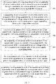
- FIG. 1 is an illustrative drawing of a power supply controlling device according to a first preferred embodiment of the present invention
- FIG. 2 is a relationship drawing of the potential difference between two ends of the resistance and the corresponding resistance
- FIG. 3 is a relationship drawing of the maximum power value and the resistance
- FIG. 4 is a relationship drawing of output data and a current through the resistance
- FIG. 5 is a relationship drawing of the power consumption value and the potential difference between two ends of the resistance
- FIG. 6 is an illustrative drawing of a power supply controlling device according to a second preferred embodiment of the present invention.
- FIG. 7 is a flow diagram of a controlling method of the power supply controlling device according to the present invention.
- FIG. 1 is an illustrative drawing of a power supply controlling device 100 according to a first preferred embodiment of the present invention.
- the power supply controlling device 100 comprises a power source 170 , a plurality of connecting ports 182 , a plurality of converters 184 , and a power supply controlling module 102 .
- the power supply controlling module 102 comprises a plurality of control units 115 and a resistance 130 (Rp).
- the control units 115 are electrically connected in parallel, and then are connected with the resistance 130 . Each of the control units 115 respectively connects with each of the connecting ports 182 .
- the control units 115 comprise a first control unit 110 and at least one second control unit 120 .
- the power supply controlling module 102 only has one first control unit 110 , but multiple second control units 120 .
- the first control unit 110 comprises a detecting circuit 111 and a first control circuit 112 , which respectively electrically connects with the resistance 130 .
- Each of the at least one second control units 120 comprises a second control circuit 112 , which respectively connects with the resistance 130 .
- the detecting circuit 111 comprises a first power source 171 , which generates a first current 161 , to derive a maximum power value of the power source 170 .
- the detecting circuit 111 , the first control circuit 112 , and the second control circuit 112 are electrically connected in parallel, then being connected with the resistance 130 .
- the first control unit 110 and the at least one second control unit 120 are electrically connected in parallel, and then are connected with the resistance 130 .
- the detecting circuit 111 comprises the first power source 171 , which generates a first current 161 .
- the first control circuit 112 and the second control circuit 112 respectively comprise a comparing circuit 180 , which is used to compare a first voltage generated by the first current 161 , to derive the maximum power value of the power source 170 of the power supply controlling device 100 and a value of the resistance 130 .
- the first control circuit 112 and the second control circuit 112 respectively comprise a second power source 172 , which generates a second current 162 according to a comparative result of the comparing circuit 180 .
- the comparing circuit 180 is used to compare a second voltage generated by the second current 162 , to derive a power consumption value of the power supply controlling device 100 . Furthermore, the first current 161 and the second current 162 will not exist at the same time. In detail, when the power supply controlling device 100 does not connect with any electronic device, the first power source 171 outputs the first current 161 to a ground terminal through the resistance 130 . The comparing circuit 180 can derive the maximum power value (the maximum value with which the power supply controlling device 100 can provide). When the power supply controlling device 100 connects with electronic devices, the second power source 172 outputs the second current 162 to a ground terminal through the resistance 130 according to the power supply of different electronic devices. Then, the comparing circuit 180 compares a second voltage with a second predetermined voltage value, to derive the power consumption value (the power needs to be outputted by the power supply controlling device 100 ).
- the potential difference generated by the first current 161 at two ends of the resistance 130 is V Rp .
- Each control unit 115 is used to control a power supply of one connecting port.
- the first power source 171 is a stable power source with 3.3 volt.
- the present invention is able to directly broadcast the maximum power value (in a form of potential difference) of the power supply controlling device 100 at the power supply controlling device 100 , to let the control units 115 all be aware of the maximum power value of the power supply controlling device 100 .
- the detecting circuit 111 is only disposed in the first control unit 110 , the control circuit 112 is disposed in each of the control units 115 .
- the second power source 172 outputs the second current 162 to the ground terminal 150 through the resistance 130 .
- Each control unit 115 calculates the single power consumption value of each control unit 115 according to the second current 162 and the resistance 130 .
- Each control unit 115 calculates an excess power value (power budget) according to the maximum power value and the single power consumption value. Perfectly, the detecting circuit 111 and the control circuit 112 has reversal conduction status, so it is possible to individually detect the maximum power value and the single power consumption value.
- the converters 184 receive the power of the power source 170 and individually control the power supply of the connecting ports 182 corresponding to the control unit 115 .
- the converters corresponding to the control units partially turn on the control unit 115 while the excess power value is equal to or greater than a predetermined value or partially turn off the control unit 115 while the excess power value is less than the predetermined value.
- supply power can divide into normal power supply (according to the power request of the electronic device) and limiting power supply (lower than the power request of the electronic device).
- FIG. 2 is a relationship drawing of the potential difference between two ends of the resistance and the corresponding resistance.
- V Rp When the V Rp is between 1.5-2.5 volts, it means the resistance value is 200 k ohm; when the V Rp is between 0.75-1.5 volts, it means the resistance value is 100 k ohm; when the V Rp is between 0.375-0.75 volts, it means the resistance value is 50 k ohm; when the V Rp is between 0.125-0.375 volts, it means the resistance value is 25 k ohm.
- the comparing circuit 180 compares the V Rp and the first predetermined voltage value, to make the whole circuit know the value of the resistance 130 .
- the value of the resistance 130 is designed by the maximum power value of the power source 170 , hence, the maximum power value of the power source 170 is known by deriving the value of the resistance 130 .
- the first predetermined voltage value is between 0.125-2.5 volts, with loop calculation of the comparing circuit 180 , to know the value of the resistance 130 with which the V Rp corresponds.
- the relationship between the volt ranges and the corresponding resistance values of the preferred embodiment can be changed according to different requests, and is not limited to this preferred embodiment.
- FIG. 3 is a relationship drawing of the maximum power value and the resistance.
- the value of the resistance 130 is designed by the maximum power value of the power source 170 , hence, the maximum power value of the power source 170 is derived by knowing the value of the resistance 130 .
- the relationship between the maximum power value and the corresponding resistance values of the preferred embodiment can be changed according to different requests, and is not limited to this preferred embodiment.
- FIG. 4 is a relationship drawing of output data and a current through the resistance.
- FIG. 5 is a relationship drawing of the power consumption value and the potential difference between two ends of the resistance.
- the V Rp means the potential difference between two ends of the resistance 130 .
- the output data comprises voltages of the connecting ports (VBUS), outputting current of the connecting ports, and outputting power.
- VBUS connecting ports
- the second power source 172 of the control unit 115 connecting with the electronic device outputs the second current 162 with 5 ⁇ A; if the resistance is 25 k ohm, the control unit 115 connecting with the electronic device outputs the second current 162 with 40 ⁇ A.
- the second power source 172 generates a second current 162 according to a comparative result of the comparing circuit 180 (see above description).
- the present invention divides 0-60 watts into 10 output voltages, with different designs, it is possible to have different quantities of output voltages.
- the single power consumption value is known as 60 watts.
- the control units 115 of the circuit all can know one of the single power consumption values by the V Rp .
- the single power consumption value can be derived as 3 volts by level-by-level comparison with multiple comparators.
- the present invention is able to directly broadcast the maximum power value (in a form of potential difference) of the power supply controlling device 100 at the power supply controlling device 100 , to let the control units 115 all be aware of the maximum power value of the power supply controlling device 100 .
- the comparing circuit 180 compares the second voltage generated by the second current 162 , to derive a power consumption value of the power supply controlling device 100 .
- the second current 162 outputted from the second power source 172 is 5 ⁇ A.
- the V Rp is derived as 1 volt according to the second current 162 (5 ⁇ A) and the resistance 130 (200 k ohm), then, the power consumption value is known as 24 watts according to the FIG. 5 .
- the relationship between the second current 162 and the corresponding resistance values of the preferred embodiment can be changed according to different requests, and is not limited to this preferred embodiment.
- the relationship between the V Rp and the power consumption values of the preferred embodiment can be changed according to different requests, and is not limit to this preferred embodiment.
- the first power source 171 outputs the first current 161 (10 ⁇ A), V Rp is equal to 1.25 volts, the resistance 130 is equal to 100 k ohm, then the maximum power value of the power supply controlling device 100 is 36 watts, the control units 115 knows the maximum power value by voltage means (1.25 volts).
- the second power source 172 outputs a second current 162 (5 ⁇ A), which means the power consumption value (power needed to be outputted) of the power supply controlling device 100 is 12 watts.
- the rest connecting ports 182 will stop supplying power to electronic devices needing more than 5 volts (such as type-C 3.0 A, Auto 2.4 A).
- the rest connecting ports 182 when the excess power value of the power supply controlling device 100 is 12 watts, the rest connecting ports 182 will stop supplying power to electronic devices needing more than 5 volts (such as QC3.0, PE+2.0, SFCP, HFCP); when the excess power value of the power supply controlling device 100 is 0 or 6 watts, the rest connecting ports 182 will stop supplying power to electronic devices needing more than 5 volts (such as type-C 3.0 A, Auto 2.4 A); when the excess power value of the power supply controlling device 100 is less than 0 watts, the rest connecting ports 182 will stop to supply power to all electronic devices.
- the maximum power value of the power supply controlling device 100 is 24 volts.
- the power supply controlling device 100 will stop supplying power to electronic devices needing more than 5 volts (such as type-C 3.0 A, Auto 2.4 A) and limit the electronic devices which continuingly connect with the power supply controlling device 100 with charging ability of only 7.5 watts (5 volts, 1.5 amps).
- the power supply controlling device 100 will stop supplying power to electronic devices needing more than 5 volts (such as type-C 3.0 A, Auto 2.4 A) and limit the electronic devices which continuingly connect with the power supply controlling device 100 with charging ability of only 7.5 watts (5 volts, 1.5 amps).
- the power supply controlling device 100 will stop supplying power to electronic devices needing more than 5 volts (such as type-C 3.0 A, Auto 2.4 A) and limit the electronic devices which continuingly connect with the power supply controlling device 100 with charging ability of only 15 watts (5 volts, 3.0 amps).
- FIG. 6 is an illustrative drawing of a power supply controlling device 200 according to a second preferred embodiment of the present invention.
- the difference between the second preferred embodiment and the first preferred embodiment is: the at least one second control unit 120 is replaced by multiple first control units 110 .
- the control circuit 112 of only one of the first control unit 110 is connected with the resistance 130 .
- FIG. 7 is a flow diagram of a controlling method of the power supply controlling device according to the present invention (please refer to the numerals of FIG. 6 ).
- a first power source 171 of a detecting circuit 111 of one of a plurality of control units 115 outputs a first current 161 to a ground terminal 150 through a resistance 130 , the control units 115 are connected in parallel, then connecting with the resistance 130 ;
- a comparing circuit 180 of a control circuit 112 of the control units 115 compares a first voltage generated by the first current 161 with a first predetermined voltage value, to derive a maximum power value of the power source 170 of the power supply controlling device 200 and a value of the resistance;
- a second power source 172 of the control circuit 112 of each of the control units 115 outputs a second current 162 to the ground terminal 150 through the resistance 130 , according to a comparative result of the comparing
Abstract
Description
Claims (7)
Applications Claiming Priority (3)
| Application Number | Priority Date | Filing Date | Title |
|---|---|---|---|
| TW105114029 | 2016-05-05 | ||
| TW105114029A | 2016-05-05 | ||
| TW105114029A TWI603563B (en) | 2016-05-05 | 2016-05-05 | Control unit for power supply, multi ports power controlling module, device and controlling method of the same |
Publications (2)
| Publication Number | Publication Date |
|---|---|
| US20170324241A1 US20170324241A1 (en) | 2017-11-09 |
| US10790687B2 true US10790687B2 (en) | 2020-09-29 |
Family
ID=60242599
Family Applications (1)
| Application Number | Title | Priority Date | Filing Date |
|---|---|---|---|
| US15/586,309 Active 2038-09-02 US10790687B2 (en) | 2016-05-05 | 2017-05-04 | Power supply control unit, controlling module, controlling device and controlling method of the same |
Country Status (3)
| Country | Link |
|---|---|
| US (1) | US10790687B2 (en) |
| CN (1) | CN107404211B (en) |
| TW (1) | TWI603563B (en) |
Families Citing this family (2)
| Publication number | Priority date | Publication date | Assignee | Title |
|---|---|---|---|---|
| CN106685022A (en) * | 2017-03-27 | 2017-05-17 | 深圳市华凯联有限公司 | Device for realizing fast charging and fast discharging of power supply for emergency starting of automobile |
| CN109066874A (en) * | 2018-08-30 | 2018-12-21 | 北京小米移动软件有限公司 | Fast charge method and device, electronic equipment, computer readable storage medium |
Citations (17)
| Publication number | Priority date | Publication date | Assignee | Title |
|---|---|---|---|---|
| TW336550U (en) | 1998-02-27 | 1998-07-11 | Jie-Cong Ji | Automatic blackboard eraser |
| TW462454U (en) | 2000-04-21 | 2001-11-01 | Yu Sheng Tubes Co Ltd | Improved structure for fitting of propane gas tube |
| US20030025401A1 (en) * | 2001-08-01 | 2003-02-06 | Vlad Popescu-Stanesti | Intelligent adapter |
| US20040075600A1 (en) * | 2002-10-16 | 2004-04-22 | Perkinelmer Inc. A Massachusetts Corporation | Data processor controlled DC to DC converter system and method of operation |
| US20050225292A1 (en) * | 2002-07-01 | 2005-10-13 | Jean-Jacques Damlamian | Charger and recharger device |
| US20060112285A1 (en) | 2004-11-19 | 2006-05-25 | Linear Technology Corporation | Analog power management within power over ethernet system |
| CN1954469A (en) | 2004-05-18 | 2007-04-25 | 罗姆股份有限公司 | Excess current detecting circuit and power supply device provided with it |
| GB2437622A (en) * | 2006-04-21 | 2007-10-31 | Dell Products Lp | Controlling voltage regulators to extend battery life |
| US20090177906A1 (en) * | 2006-08-30 | 2009-07-09 | Paniagua Jr Frank | Powering An Electrical Device Through a Legacy Adapter Capable of Digital Communication |
| US20110179291A1 (en) * | 2010-01-20 | 2011-07-21 | Dell Products L.P. | Power adaptor detection system |
| US7994660B2 (en) | 2001-08-01 | 2011-08-09 | 02Micro International Limited | Supply topology with power limiting feedback loop |
| US20110278923A1 (en) * | 2010-05-12 | 2011-11-17 | Apple Inc. | Multi-output power supply |
| US20140009977A1 (en) | 2012-07-04 | 2014-01-09 | Leadtrend Technology Corporation | Constant Current Control Units and Control Methods Thereof for Primary Side Control |
| US8786268B2 (en) | 2012-06-28 | 2014-07-22 | Linear Technology Corporation | Current mode voltage regulator with auto-compensation |
| US20140292070A1 (en) * | 2013-03-27 | 2014-10-02 | Hewlett-Packard Development Company, L.P. | Adapter to provide power from a power supply |
| TW201501443A (en) | 2013-06-28 | 2015-01-01 | Good Way Technology Co Ltd | Hub device and power management method applicable to the hub device |
| US20170222436A1 (en) * | 2014-08-06 | 2017-08-03 | Philips Lighting Holding B.V. | Power distribution system |
-
2016
- 2016-05-05 TW TW105114029A patent/TWI603563B/en active
-
2017
- 2017-05-03 CN CN201710302753.1A patent/CN107404211B/en active Active
- 2017-05-04 US US15/586,309 patent/US10790687B2/en active Active
Patent Citations (19)
| Publication number | Priority date | Publication date | Assignee | Title |
|---|---|---|---|---|
| TW336550U (en) | 1998-02-27 | 1998-07-11 | Jie-Cong Ji | Automatic blackboard eraser |
| TW462454U (en) | 2000-04-21 | 2001-11-01 | Yu Sheng Tubes Co Ltd | Improved structure for fitting of propane gas tube |
| US20030025401A1 (en) * | 2001-08-01 | 2003-02-06 | Vlad Popescu-Stanesti | Intelligent adapter |
| US7994660B2 (en) | 2001-08-01 | 2011-08-09 | 02Micro International Limited | Supply topology with power limiting feedback loop |
| US20050225292A1 (en) * | 2002-07-01 | 2005-10-13 | Jean-Jacques Damlamian | Charger and recharger device |
| US20040075600A1 (en) * | 2002-10-16 | 2004-04-22 | Perkinelmer Inc. A Massachusetts Corporation | Data processor controlled DC to DC converter system and method of operation |
| CN1954469A (en) | 2004-05-18 | 2007-04-25 | 罗姆股份有限公司 | Excess current detecting circuit and power supply device provided with it |
| US20070229041A1 (en) | 2004-05-18 | 2007-10-04 | Hirokazu Oki | Excess Current Detecting Circuit and Power Supply Device Provided with it |
| CN101061668A (en) | 2004-11-19 | 2007-10-24 | 凌特公司 | Analog power management within power over Ethernet system |
| US20060112285A1 (en) | 2004-11-19 | 2006-05-25 | Linear Technology Corporation | Analog power management within power over ethernet system |
| GB2437622A (en) * | 2006-04-21 | 2007-10-31 | Dell Products Lp | Controlling voltage regulators to extend battery life |
| US20090177906A1 (en) * | 2006-08-30 | 2009-07-09 | Paniagua Jr Frank | Powering An Electrical Device Through a Legacy Adapter Capable of Digital Communication |
| US20110179291A1 (en) * | 2010-01-20 | 2011-07-21 | Dell Products L.P. | Power adaptor detection system |
| US20110278923A1 (en) * | 2010-05-12 | 2011-11-17 | Apple Inc. | Multi-output power supply |
| US8786268B2 (en) | 2012-06-28 | 2014-07-22 | Linear Technology Corporation | Current mode voltage regulator with auto-compensation |
| US20140009977A1 (en) | 2012-07-04 | 2014-01-09 | Leadtrend Technology Corporation | Constant Current Control Units and Control Methods Thereof for Primary Side Control |
| US20140292070A1 (en) * | 2013-03-27 | 2014-10-02 | Hewlett-Packard Development Company, L.P. | Adapter to provide power from a power supply |
| TW201501443A (en) | 2013-06-28 | 2015-01-01 | Good Way Technology Co Ltd | Hub device and power management method applicable to the hub device |
| US20170222436A1 (en) * | 2014-08-06 | 2017-08-03 | Philips Lighting Holding B.V. | Power distribution system |
Also Published As
| Publication number | Publication date |
|---|---|
| CN107404211A (en) | 2017-11-28 |
| TWI603563B (en) | 2017-10-21 |
| CN107404211B (en) | 2021-06-15 |
| TW201740650A (en) | 2017-11-16 |
| US20170324241A1 (en) | 2017-11-09 |
Similar Documents
| Publication | Publication Date | Title |
|---|---|---|
| TWI584111B (en) | Electronic device | |
| JP6596447B2 (en) | Power feeding device and control circuit thereof, power receiving device and control circuit thereof, electronic device and charging adapter using the same, and abnormality detection method | |
| US20150311705A1 (en) | Multiport power converter with load detection capabilities | |
| US9787124B2 (en) | Charging device | |
| TWI597918B (en) | Battery charge system and method capable of operating in different configurations | |
| US20160094071A1 (en) | Controlling power in a multi-port usb power delivery system | |
| TWI683198B (en) | Multi-port power supply apparatus and power suppling method thereof | |
| JP6943668B2 (en) | Electronics | |
| US10790687B2 (en) | Power supply control unit, controlling module, controlling device and controlling method of the same | |
| JP2013059245A (en) | Overvoltage protection circuit and portable electronic device including the same | |
| US10305278B2 (en) | Voltage control system | |
| JP6194419B2 (en) | Serial bus voltage compensation | |
| CN107482612B (en) | Electronic equipment and power supply method | |
| JP2016085107A (en) | Overcurrent detection circuit and usb power supply device using the same, electronic equipment, and overcurrent detection method | |
| US20120313687A1 (en) | Connection apparatus | |
| US20140159490A1 (en) | Power converter, electronic device and method for detecting output power of power converter | |
| US20140319915A1 (en) | Power adapter with proportional current sharing and mobile electronic device having the same | |
| TWI685167B (en) | Current regulation system | |
| US11243551B1 (en) | Method and system of dynamic voltage compensation for electrical power delivery | |
| CN210428227U (en) | Output voltage regulator of power module | |
| KR20200041249A (en) | Electronic apparatus and power supply module | |
| TWM534837U (en) | Control unit for power supply, multi ports power controlling module and device | |
| KR101793523B1 (en) | Apparatus and method for assisting power supply | |
| US20060291116A1 (en) | Power supply load selection control circuit | |
| US20140253085A1 (en) | Digital programmable control systems |
Legal Events
| Date | Code | Title | Description |
|---|---|---|---|
| AS | Assignment |
Owner name: GENESYS LOGIC, INC., TAIWAN Free format text: ASSIGNMENT OF ASSIGNORS INTEREST;ASSIGNORS:LEE, WEI-TE;CHENG, CHIEN-KANG;REEL/FRAME:042233/0747 Effective date: 20170421 |
|
| STPP | Information on status: patent application and granting procedure in general |
Free format text: DOCKETED NEW CASE - READY FOR EXAMINATION |
|
| STPP | Information on status: patent application and granting procedure in general |
Free format text: NON FINAL ACTION MAILED |
|
| STPP | Information on status: patent application and granting procedure in general |
Free format text: NOTICE OF ALLOWANCE MAILED -- APPLICATION RECEIVED IN OFFICE OF PUBLICATIONS |
|
| STPP | Information on status: patent application and granting procedure in general |
Free format text: NOTICE OF ALLOWANCE MAILED -- APPLICATION RECEIVED IN OFFICE OF PUBLICATIONS |
|
| STPP | Information on status: patent application and granting procedure in general |
Free format text: PUBLICATIONS -- ISSUE FEE PAYMENT RECEIVED |
|
| STCF | Information on status: patent grant |
Free format text: PATENTED CASE |
|
| MAFP | Maintenance fee payment |
Free format text: PAYMENT OF MAINTENANCE FEE, 4TH YR, SMALL ENTITY (ORIGINAL EVENT CODE: M2551); ENTITY STATUS OF PATENT OWNER: SMALL ENTITY Year of fee payment: 4 |