US10787914B2 - CMC airfoil with monolithic ceramic core - Google Patents
CMC airfoil with monolithic ceramic core Download PDFInfo
- Publication number
- US10787914B2 US10787914B2 US14/912,317 US201414912317A US10787914B2 US 10787914 B2 US10787914 B2 US 10787914B2 US 201414912317 A US201414912317 A US 201414912317A US 10787914 B2 US10787914 B2 US 10787914B2
- Authority
- US
- United States
- Prior art keywords
- airfoil
- core
- skin
- ceramic
- cmc
- Prior art date
- Legal status (The legal status is an assumption and is not a legal conclusion. Google has not performed a legal analysis and makes no representation as to the accuracy of the status listed.)
- Active, expires
Links
- 239000000919 ceramic Substances 0.000 title claims description 128
- 239000007791 liquid phase Substances 0.000 claims abstract description 23
- 230000001052 transient effect Effects 0.000 claims abstract description 23
- 238000005304 joining Methods 0.000 claims abstract description 22
- 239000011153 ceramic matrix composite Substances 0.000 claims description 108
- TWNQGVIAIRXVLR-UHFFFAOYSA-N oxo(oxoalumanyloxy)alumane Chemical compound O=[Al]O[Al]=O TWNQGVIAIRXVLR-UHFFFAOYSA-N 0.000 claims description 36
- 238000000034 method Methods 0.000 claims description 33
- 229910052581 Si3N4 Inorganic materials 0.000 claims description 24
- HQVNEWCFYHHQES-UHFFFAOYSA-N silicon nitride Chemical compound N12[Si]34N5[Si]62N3[Si]51N64 HQVNEWCFYHHQES-UHFFFAOYSA-N 0.000 claims description 24
- HBMJWWWQQXIZIP-UHFFFAOYSA-N silicon carbide Chemical compound [Si+]#[C-] HBMJWWWQQXIZIP-UHFFFAOYSA-N 0.000 claims description 18
- 239000010410 layer Substances 0.000 claims description 16
- 239000011229 interlayer Substances 0.000 claims description 13
- 239000000463 material Substances 0.000 claims description 13
- 238000002844 melting Methods 0.000 claims description 12
- 230000008018 melting Effects 0.000 claims description 12
- RVTZCBVAJQQJTK-UHFFFAOYSA-N oxygen(2-);zirconium(4+) Chemical compound [O-2].[O-2].[Zr+4] RVTZCBVAJQQJTK-UHFFFAOYSA-N 0.000 claims description 12
- MTPVUVINMAGMJL-UHFFFAOYSA-N trimethyl(1,1,2,2,2-pentafluoroethyl)silane Chemical compound C[Si](C)(C)C(F)(F)C(F)(F)F MTPVUVINMAGMJL-UHFFFAOYSA-N 0.000 claims description 12
- 229910001928 zirconium oxide Inorganic materials 0.000 claims description 12
- 239000000470 constituent Substances 0.000 claims description 9
- 239000011159 matrix material Substances 0.000 claims description 9
- 239000000835 fiber Substances 0.000 claims description 8
- OKTJSMMVPCPJKN-UHFFFAOYSA-N Carbon Chemical compound [C] OKTJSMMVPCPJKN-UHFFFAOYSA-N 0.000 claims description 6
- 229910052799 carbon Inorganic materials 0.000 claims description 6
- 150000001875 compounds Chemical class 0.000 claims description 6
- UONOETXJSWQNOL-UHFFFAOYSA-N tungsten carbide Chemical compound [W+]#[C-] UONOETXJSWQNOL-UHFFFAOYSA-N 0.000 claims description 6
- 238000010438 heat treatment Methods 0.000 claims description 3
- 239000007789 gas Substances 0.000 description 10
- 239000011888 foil Substances 0.000 description 7
- 238000001816 cooling Methods 0.000 description 5
- 230000014759 maintenance of location Effects 0.000 description 5
- 238000004891 communication Methods 0.000 description 4
- 239000000758 substrate Substances 0.000 description 4
- 230000008901 benefit Effects 0.000 description 3
- 229910010293 ceramic material Inorganic materials 0.000 description 3
- PXHVJJICTQNCMI-UHFFFAOYSA-N Nickel Chemical compound [Ni] PXHVJJICTQNCMI-UHFFFAOYSA-N 0.000 description 2
- KDLHZDBZIXYQEI-UHFFFAOYSA-N Palladium Chemical compound [Pd] KDLHZDBZIXYQEI-UHFFFAOYSA-N 0.000 description 2
- 229910045601 alloy Inorganic materials 0.000 description 2
- 239000000956 alloy Substances 0.000 description 2
- 230000000712 assembly Effects 0.000 description 2
- 238000000429 assembly Methods 0.000 description 2
- 230000015572 biosynthetic process Effects 0.000 description 2
- 238000009792 diffusion process Methods 0.000 description 2
- 239000012530 fluid Substances 0.000 description 2
- 238000010348 incorporation Methods 0.000 description 2
- BASFCYQUMIYNBI-UHFFFAOYSA-N platinum Chemical compound [Pt] BASFCYQUMIYNBI-UHFFFAOYSA-N 0.000 description 2
- 230000003068 static effect Effects 0.000 description 2
- RYGMFSIKBFXOCR-UHFFFAOYSA-N Copper Chemical compound [Cu] RYGMFSIKBFXOCR-UHFFFAOYSA-N 0.000 description 1
- XUIMIQQOPSSXEZ-UHFFFAOYSA-N Silicon Chemical compound [Si] XUIMIQQOPSSXEZ-UHFFFAOYSA-N 0.000 description 1
- RTAQQCXQSZGOHL-UHFFFAOYSA-N Titanium Chemical compound [Ti] RTAQQCXQSZGOHL-UHFFFAOYSA-N 0.000 description 1
- 238000010521 absorption reaction Methods 0.000 description 1
- 238000006664 bond formation reaction Methods 0.000 description 1
- 238000005219 brazing Methods 0.000 description 1
- 238000005266 casting Methods 0.000 description 1
- 238000006243 chemical reaction Methods 0.000 description 1
- 229910017052 cobalt Inorganic materials 0.000 description 1
- 239000010941 cobalt Substances 0.000 description 1
- GUTLYIVDDKVIGB-UHFFFAOYSA-N cobalt atom Chemical compound [Co] GUTLYIVDDKVIGB-UHFFFAOYSA-N 0.000 description 1
- 230000006835 compression Effects 0.000 description 1
- 238000007906 compression Methods 0.000 description 1
- 238000010276 construction Methods 0.000 description 1
- 229910052802 copper Inorganic materials 0.000 description 1
- 239000010949 copper Substances 0.000 description 1
- 230000001747 exhibiting effect Effects 0.000 description 1
- 239000000446 fuel Substances 0.000 description 1
- PCHJSUWPFVWCPO-UHFFFAOYSA-N gold Chemical compound [Au] PCHJSUWPFVWCPO-UHFFFAOYSA-N 0.000 description 1
- 229910052737 gold Inorganic materials 0.000 description 1
- 239000010931 gold Substances 0.000 description 1
- 238000004519 manufacturing process Methods 0.000 description 1
- 239000000203 mixture Substances 0.000 description 1
- 229910052759 nickel Inorganic materials 0.000 description 1
- 229910052758 niobium Inorganic materials 0.000 description 1
- 239000010955 niobium Substances 0.000 description 1
- GUCVJGMIXFAOAE-UHFFFAOYSA-N niobium atom Chemical compound [Nb] GUCVJGMIXFAOAE-UHFFFAOYSA-N 0.000 description 1
- 229910052763 palladium Inorganic materials 0.000 description 1
- 229910052697 platinum Inorganic materials 0.000 description 1
- 239000002243 precursor Substances 0.000 description 1
- 238000012545 processing Methods 0.000 description 1
- 239000003870 refractory metal Substances 0.000 description 1
- 229910052710 silicon Inorganic materials 0.000 description 1
- 239000010703 silicon Substances 0.000 description 1
- 238000007711 solidification Methods 0.000 description 1
- 230000008023 solidification Effects 0.000 description 1
- 239000000126 substance Substances 0.000 description 1
- 229910052715 tantalum Inorganic materials 0.000 description 1
- GUVRBAGPIYLISA-UHFFFAOYSA-N tantalum atom Chemical compound [Ta] GUVRBAGPIYLISA-UHFFFAOYSA-N 0.000 description 1
- 229910052719 titanium Inorganic materials 0.000 description 1
- 239000010936 titanium Substances 0.000 description 1
- 230000007704 transition Effects 0.000 description 1
- 229910052720 vanadium Inorganic materials 0.000 description 1
- GPPXJZIENCGNKB-UHFFFAOYSA-N vanadium Chemical compound [V]#[V] GPPXJZIENCGNKB-UHFFFAOYSA-N 0.000 description 1
- 230000003313 weakening effect Effects 0.000 description 1
- 238000009736 wetting Methods 0.000 description 1
Images


Classifications
-
- F—MECHANICAL ENGINEERING; LIGHTING; HEATING; WEAPONS; BLASTING
- F01—MACHINES OR ENGINES IN GENERAL; ENGINE PLANTS IN GENERAL; STEAM ENGINES
- F01D—NON-POSITIVE DISPLACEMENT MACHINES OR ENGINES, e.g. STEAM TURBINES
- F01D5/00—Blades; Blade-carrying members; Heating, heat-insulating, cooling or antivibration means on the blades or the members
- F01D5/12—Blades
- F01D5/28—Selecting particular materials; Particular measures relating thereto; Measures against erosion or corrosion
- F01D5/284—Selection of ceramic materials
-
- F—MECHANICAL ENGINEERING; LIGHTING; HEATING; WEAPONS; BLASTING
- F01—MACHINES OR ENGINES IN GENERAL; ENGINE PLANTS IN GENERAL; STEAM ENGINES
- F01D—NON-POSITIVE DISPLACEMENT MACHINES OR ENGINES, e.g. STEAM TURBINES
- F01D5/00—Blades; Blade-carrying members; Heating, heat-insulating, cooling or antivibration means on the blades or the members
- F01D5/12—Blades
- F01D5/28—Selecting particular materials; Particular measures relating thereto; Measures against erosion or corrosion
- F01D5/282—Selecting composite materials, e.g. blades with reinforcing filaments
-
- F—MECHANICAL ENGINEERING; LIGHTING; HEATING; WEAPONS; BLASTING
- F01—MACHINES OR ENGINES IN GENERAL; ENGINE PLANTS IN GENERAL; STEAM ENGINES
- F01D—NON-POSITIVE DISPLACEMENT MACHINES OR ENGINES, e.g. STEAM TURBINES
- F01D5/00—Blades; Blade-carrying members; Heating, heat-insulating, cooling or antivibration means on the blades or the members
- F01D5/12—Blades
- F01D5/14—Form or construction
- F01D5/18—Hollow blades, i.e. blades with cooling or heating channels or cavities; Heating, heat-insulating or cooling means on blades
- F01D5/187—Convection cooling
-
- F—MECHANICAL ENGINEERING; LIGHTING; HEATING; WEAPONS; BLASTING
- F05—INDEXING SCHEMES RELATING TO ENGINES OR PUMPS IN VARIOUS SUBCLASSES OF CLASSES F01-F04
- F05D—INDEXING SCHEME FOR ASPECTS RELATING TO NON-POSITIVE-DISPLACEMENT MACHINES OR ENGINES, GAS-TURBINES OR JET-PROPULSION PLANTS
- F05D2220/00—Application
- F05D2220/30—Application in turbines
- F05D2220/32—Application in turbines in gas turbines
-
- F—MECHANICAL ENGINEERING; LIGHTING; HEATING; WEAPONS; BLASTING
- F05—INDEXING SCHEMES RELATING TO ENGINES OR PUMPS IN VARIOUS SUBCLASSES OF CLASSES F01-F04
- F05D—INDEXING SCHEME FOR ASPECTS RELATING TO NON-POSITIVE-DISPLACEMENT MACHINES OR ENGINES, GAS-TURBINES OR JET-PROPULSION PLANTS
- F05D2230/00—Manufacture
- F05D2230/20—Manufacture essentially without removing material
- F05D2230/23—Manufacture essentially without removing material by permanently joining parts together
-
- F—MECHANICAL ENGINEERING; LIGHTING; HEATING; WEAPONS; BLASTING
- F05—INDEXING SCHEMES RELATING TO ENGINES OR PUMPS IN VARIOUS SUBCLASSES OF CLASSES F01-F04
- F05D—INDEXING SCHEME FOR ASPECTS RELATING TO NON-POSITIVE-DISPLACEMENT MACHINES OR ENGINES, GAS-TURBINES OR JET-PROPULSION PLANTS
- F05D2300/00—Materials; Properties thereof
- F05D2300/60—Properties or characteristics given to material by treatment or manufacturing
- F05D2300/603—Composites; e.g. fibre-reinforced
- F05D2300/6033—Ceramic matrix composites [CMC]
Definitions
- the disclosed subject matter relates generally to nonmetallic airfoils and more particularly to ceramic airfoils.
- Laminated ceramic matrix composite (CMC) airfoils are well known for gas turbine engines, but have certain shortcomings Though extremely light in weight and exhibiting tolerance of foreign object damage (FOD), they are expensive to process into complex aerodynamic shapes. Conversely, ceramic airfoils are easier to form than laminated CMC airfoils, but are prone to large scale fracture due to FOD.
- CMC ceramic matrix composite
- An airfoil comprises a core having a first surface, a skin having a second surface disposed over at least a portion of the first surface of the core, and at least one of a transient liquid phase (TLP) bond and a partial transient liquid phase (PTLP) bond.
- TLP transient liquid phase
- PTLP partial transient liquid phase
- a method for making a hybrid airfoil component comprises providing a ceramic airfoil core.
- a ceramic matrix composite (CMC) airfoil skin is placed over at least a portion of the ceramic airfoil core.
- the CMC skin is joined to the ceramic core to define an airfoil shape.
- the joining step is performed at least in part by forming a partial transient liquid phase (PTLP) bond between the ceramic core and the CMC skin.
- PTLP partial transient liquid phase
- FIG. 1 shows a gas turbine engine
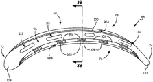
- FIG. 2 is a portion of a rotor disk and a hybrid ceramic/CMC airfoil.
- FIG. 3A is a first sectional view taken across line 3 A- 3 A of the airfoil shown in FIG. 2 .
- FIG. 3B is a second sectional view of the airfoil taken across line 3 B- 3 B of FIG. 3A .
- FIG. 4A shows a first PTLP bond joining the suction side CMC skin to the adjacent ceramic core.
- FIG. 4B shows an example configuration setting up the first PTLP bond shown in FIG. 4A .
- FIG. 5A depicts a first alternate configuration of an airfoil with PTLP bonds on either side of a thermal protection structure, which together join the CMC skin and the ceramic core.
- FIG. 5B is a second alternate configuration of an airfoil with a PTLP bond between two thermal protection elements forming a thermal protection structure joining the CMC skin and the ceramic core.
- FIG. 6 shows steps of a method for making a hybrid ceramic/CMC airfoil.
- FIG. 1 is a schematic view of gas turbine engine 20 .
- Gas turbine engine 20 is disclosed herein as a two-spool turbofan that generally incorporates fan section 22 , compressor section 24 , combustor section 26 and turbine section 28 , although alternative gas turbine designs (including designs utilizing a power turbine in place of fan section 22 ) may also benefit from the described subject matter.
- fan section 22 drives air along bypass flowpath B
- compressor section 24 drives air along a core flowpath for compression and communication into the combustor section 26 , and then expansion through the turbine section 28 .
- Dual-spool embodiments such as example engine 20 generally include low-speed spool 30 and high-speed spool 32 mounted for rotation about an engine central longitudinal axis A. Spools 30 , 32 rotate relative to engine static structure 36 via several bearing systems 38 . It should be understood that different numbers of spools, as well as various bearing systems 38 may alternatively or additionally be provided.
- Low-speed spool 30 generally includes inner shaft 40 that interconnects a fan 42 , low-pressure compressor 44 and low-pressure turbine 46 .
- inner shaft 40 can be connected to fan 42 through geared architecture 48 to drive fan 42 at a lower speed than low-speed spool 30 .
- High-speed spool 32 includes outer shaft 50 that interconnects high-pressure compressor 52 and high-pressure turbine 54 .
- Combustor 56 is arranged between high-pressure compressor 52 and high-pressure turbine 54 .
- Mid-turbine frame 57 of the engine static structure 36 can be arranged axially between high-pressure turbine 54 and low-pressure turbine 46 .
- Mid-turbine frame 57 can further support bearing systems 38 in turbine section 28 .
- Inner shaft 40 and outer shaft 50 are concentric and rotate via bearing systems 38 about the engine central longitudinal axis A which is collinear with their longitudinal axes.
- the core airflow is compressed by low-pressure compressor 44 and then by high-pressure compressor 52 , mixed and burned with fuel in combustor 56 , then expanded over high-pressure turbine 54 and low-pressure turbine 46 .
- Combustor 56 is therefore in fluid communication with the compressor section, to receive air compressed by low-pressure compressor 44 and high-pressure compressor 52 .
- Mid-turbine frame 57 can also include airfoils 59 which are in the core airflow path.
- Turbines 46 and 54 are in fluid communication with combustor 56 , wherein the expanding gas provided by combustor 56 drives the respective low-speed spool 30 and high-speed spool 32 .
- FIG. 2 shows a portion of gas turbine rotor assembly 62 , which includes rotor disk 64 with a plurality of circumferentially distributed hybrid rotor blades 66 (one shown in FIG. 2 ).
- Hybrid rotor blade 66 includes airfoil section 68 , root section 70 , leading edge 72 , trailing edge 74 , pressure surface 76 , suction surface 78 , radial retention slots 80 , pressure-side root bearing surface 82 , disk bearing surfaces 84 , disk teeth 86 , forward bearing surface 88 , aft bearing surface 90 , retention ring 92 , and shim 94 .
- rotor assembly 62 and/or hybrid rotor blade 66 are disposed in the hot section, such as high-pressure turbine 54 , or low-pressure turbine 46 as shown in FIG. 1 . Additionally or alternatively, rotor assembly 62 may be disposed in fan section 22 , low-pressure compressor section 44 , and/or high-pressure compressor section 50 . In other alternative embodiments, hybrid airfoil sections can be formed in a similar manner for one or more stator assemblies in these sections of engine 20 .
- airfoil section 68 can include leading edge 72 , trailing edge 74 , pressure surface 76 , and suction surface 78 .
- Root section 70 can be a single root with circumferentially opposed bearing surfaces for securing hybrid blade 66 into a corresponding radial retention slot 80 of disk 64 .
- root section 70 can be a multilobe root.
- pressure-side root bearing surface 82 and an opposing suction-side bearing surface (not visible) mate with respective bearing surfaces 84 of disk teeth 86 , which define a longitudinal extent of slot 80 .
- Root section 70 includes longitudinally facing forward bearing surface 88 and aft bearing surface 90 (not visible in FIG. 2 ).
- At least one of these longitudinally facing bearing surfaces can be secured using one or more retention rings 92 , or alternatively using another bearing surface of the disk (not shown).
- Shim 94 can be disposed annularly between blade root section 70 and the corresponding radial retention slot 80 .
- rotor assembly 62 can include an inner-diameter flow surface defined, for example, by a plurality of circumferentially distributed blade platforms. Such platforms may be integrally formed or secured to each hybrid blade 66 proximate the transition between airfoil section 68 and root section 70 . Likewise, certain embodiments may also include an outer-diameter flow surface that may be integrally formed or secured to each hybrid blade 66 proximate the outer tip of the airfoil. However, to better illustrate other elements, any possible inner or outer flow surface or blade platform has been omitted from the examples described herein.
- hybrid blade 66 can include a hybrid airfoil section 68 in which a core with a first (e.g., ceramic) outer surface is bonded to a second (e.g., ceramic matrix composite/CMC) inner surface of an airfoil skin.
- the skin can be disposed over at least a portion of the outer surface of the ceramic core to define one or more airfoil surfaces such as pressure surface 76 and/or suction surface 78 .
- At least one of a transient liquid phase (TLP) bond and a partial transient liquid phase (PTLP) bond can be disposed between the first outer surface and second inner surface, thereby joining the CMC skin to the ceramic core to define a shape of airfoil section 68 . Due to reduced weight and moment of inertia, as well as the ability to form complex shapes, airfoil section 68 can be highly tapered to increase engine efficiency.
- TLP transient liquid phase
- PTLP partial transient liquid phase
- FIG. 3A is a first sectional view taken across line 3 A- 3 A of the airfoil shown in FIG. 2 .
- FIG. 3B is a sectional view taken across line 3 B- 3 B of FIG. 3A , showing an example construction of hybrid blade 66 in more detail.
- airfoil section 68 of hybrid blade 66 generally includes ceramic core 96 , CMC skin portions 98 A, 98 B, and PTLP bonds 100 , 102 .
- Suction-side CMC skin portion 98 A is joined to ceramic core 96 by one or more suction-side PTLP bonds 100 .
- Pressure-side CMC skin portion 98 B can be generally spaced from ceramic core 96 except proximate a location of one or more pressure-side PTLP bonds 102 and thermal protection structures 104 . This defines one or more thermal protection spaces 106 between thermal protection structures 104 and ceramic core 96 to reduce thermal conduction from hot gases impinging on pressure-side CMC skin portion 98 B.
- the hot gases can be working gases when airfoil 68 is used in hot section and/or power turbine applications.
- Thermal protection spaces 106 can also serve as cooling passages and can be placed in communication with any cooling passages (not shown) which may be formed through ceramic core 96 .
- Thermal protection structures 104 and PTLP bond(s) 102 allow for greater differential thermal expansion between core 96 and CMC skin portion 98 B.
- the respective ceramic materials in core 96 and CMC skin portions 98 A, 98 B can be selected with less concern of damage that can be caused by differential thermal growth.
- the inner surface of the CMC skin can extend over some or all of the outer surface of the ceramic core. In the example shown, the CMC skin does not extend over the entirety of airfoil section 68 . As shown in FIG. 3A , ceramic core 96 has leading-edge portion 108 defining airfoil leading edge 72 , as well as trailing-edge portion 110 defining airfoil trailing edge 74 . This configuration is shown in part because it allows for simple incorporation of CMC sheets to define substantial portions of pressure surface 76 and suction surface 78 .
- This configuration allows for CMC skin portions 98 A, 98 B to hold together ceramic core 96 in the event of failure (e.g., from a foreign object strike) while simplifying manufacture of the outer CMC surfaces and incorporation of the same into airfoil section 68 .
- a substantially contiguous CMC skin can also extend over some or all of leading edge 72 and trailing edge 74 , as well as the airfoil tip.
- a hybrid blade also provides increased FOD resistance, especially in larger airfoils. Instead of potential perforation of a CMC blade, or failure of a ceramic blade, the energy absorption characteristics of ceramic core 96 and CMC skin portions 98 A, 98 B often will keep airfoil section 68 intact for a more graceful failure, which can prevent cascading foreign object damage to the engine.
- the hybrid configuration also offers increased flexibility in the complexity of small details and complex shapes with monolithic ceramics relative to a CMC structure. Spaces 106 can also double as skin cooling passages depending on the configuration of thermal protection structures 104 .
- Ceramic core 96 can be a monolithic ceramic, i.e., not reinforced by internal fibers or the like. However, core 96 can include cooling passages 111 formed during or after casting. In certain embodiments, ceramic core 96 includes at least one ceramic compound selected from one of: aluminum oxide (Al 2 O 3 ), silicon nitride (Si 3 N 4 ), silicon carbide (SiC), tungsten carbide (WC), and zirconium oxide (ZrO 2 ).
- Al 2 O 3 aluminum oxide
- Si 3 N 4 silicon nitride
- SiC silicon carbide
- WC tungsten carbide
- ZrO 2 zirconium oxide
- Suction- and pressure-side CMC skin portions 98 A, 98 B can be individually or integrally formed from a plurality of fibers disposed in a ceramic matrix.
- Example fibers can include combinations of silicon carbide (SiC), titanium carbide (TiC), aluminum oxide (Al 2 O 3 ), and/or carbon (C).
- the ceramic matrix can be made, for example, from aluminum oxide (Al 2 O 3 ), silicon nitride (Si 3 N 4 ), and silicon carbide (SiC), or other suitable ceramic materials.
- FIG. 3B shows additional details of airfoil section 68 .
- Respective inner surfaces 114 A, 114 B of suction-side CMC skin portion 98 A and pressure-side CMC skin portion 98 B can be bonded to outer surface(s) 112 of ceramic core 96 by way of corresponding suction- and pressure-side PTLP bonds 100 , 102 .
- Suction-side CMC skin portion 98 A can be secured directly to an outer surface of ceramic core 96 via contiguous suction-side PTLP bond 100
- pressure-side CMC skin portion 98 B can be secured indirectly to ceramic core 96 via a plurality of individual pressure-side PTLP bonds 102 .
- PTLP bonds 100 , 102 can include an alloyed interlayer having a melting temperature higher than a melting temperature of constituent elements defining the alloyed interlayer.
- the melting temperature is also higher than the bonding temperature. This results in high-temperature interlayer links between ceramic core 96 and CMC skin portions 98 A, 98 B which are more resilient and require less bonding area than a sintered connection between the ceramics. It also allows for the use of different ceramics and tailoring of mechanical and thermal properties of materials for core 96 and CMC skin portions 98 A, 98 B with much less concern for differential thermal expansion.
- FIGS. 4A and 4B show formation of PTLP bond 100 directly between inner surface 114 A of suction-side CMC skin portion 98 A and outer surface 112 of ceramic core 96 .
- a PTLP bond is one which has several similarities to brazed and diffusion-bonded connections, but which is formed at lower bonding temperatures than brazing and lower bonding pressures than diffusion bonding.
- Properly designed PTLP bonds can reduce intermaterial stresses and provide controlled diffusion between the different material interfaces.
- the lower temperatures of PTLP bond formation also mitigate potential microstructural weakening associated with other joining techniques.
- the resulting bond strength of alloyed interlayer 128 can be comparable to that of brazed, sintered, or diffusion-bonded connections and substantially maintains the structural integrity and composition of the substrates.
- FIG. 4A shows a precursor to PTLP bond 100 , PTLP bond assembly 120 , which includes refractory segment 122 , core-side foil layer 124 A, and skin-side foil layer 124 B.
- Foil layers 124 A, 124 B are shown as individual layers but one or both can alternatively comprise multiple foil layers.
- Refractory segment 122 can be, for example, nickel or an alloy thereof.
- Alternative refractory metals suitable for refractory segment 122 include gold, cobalt, copper, niobium, palladium, platinum, silicon, tantalum, titanium, vanadium, and alloys thereof.
- Foils 124 A, 124 B are selected so as to wet the ceramic substrate (here, ceramic core 96 and the ceramic matrix of CMC skin 98 A) at the bonding temperature.
- bond assembly 120 can then be maintained at a bonding temperature for a suitable time so as to homogenize the materials into PTLP bond 100 shown in FIG. 4B with alloyed interlayer 128 .
- FIG. 5A shows a configuration of PTLP bonding which incorporates thermal protection structure 104 .
- Thermal protection structure 104 along with at least one PTLP bond 102 , is disposed between inner surface 114 B of pressure-side CMC skin portion 98 B and outer surface 112 of ceramic core 96 .
- FIG. 5A differs from FIGS. 4A and 4B in that a thermal protection structure is disposed across space 106 (shown in FIG. 3B ) between surfaces 112 , 114 B.
- a thermal protection structure is disposed across space 106 (shown in FIG. 3B ) between surfaces 112 , 114 B.
- thermal protection structure 104 can be formed from a more thermally insulating ceramic relative to one or both ceramics of core 96 and CMC skin 98 B.
- each of the plurality of thermal protection structures 104 each have core side 132 and skin side 134 joined to a corresponding one of CMC skin inner surface 114 B and ceramic core outer surface 112 .
- Thermal protection structure 104 is shown here as an individual structure with both core side 132 and skin side 134 each joined to a corresponding one of ceramic core 96 and CMC skin 98 B by partial transient liquid phase (PTLP) bonds 102 .
- PTLP partial transient liquid phase
- PTLP bonds 102 can each be formed in a manner similar to that shown in FIG. 4A , in which refractory segment 122 is sandwiched between at least one foil layer on either side to form a bond assembly 120 . Bond assemblies 120 are then heated to form PTLP bonds which have a higher melting temperature than the bonding temperature. This increased melting temperature is a result of isothermal solidification of alloyed interlayer 128 which mitigates the concern of remelting the bond.
- thermal protection structure 104 is shown as a separate structure bonded on either side to each substrate (core 96 and CMC skin 98 B). This is but one illustrative example configuration. It will also be appreciated that one or more portions of thermal protection structure 104 can be integrally formed into one or both of ceramic core 96 or skin 98 B. In one example, thermal protection structure 104 is integrally formed to ceramic core 96 , eliminating the need for one of PTLP bonds 102 .
- interlocking or alternating thermal protection structures 104 can be formed on surfaces 112 , 114 B.
- FIG. 5B shows a first thermal protection element 130 A and a second element 130 B joined by PTLP bond 132 to form alternate thermal protection structure 128 .
- a combination of such elements could also allow for appropriate mistake proofing by ensuring that the proper elements 130 A, 130 B line up for each thermal protection structure 128 .
- Thermal protection structures 104 , 128 can have any suitable cross-sectional geometry.
- thermal protection structures 104 , 128 can be an array of round or square projections.
- FIG. 6 is a chart showing steps of method 200 for making a hybrid airfoiled component such as is shown in FIGS. 2-5 .
- Method 200 begins with step 202 of providing a ceramic airfoil core.
- This core may have a similar geometry as ceramic core 96 in the example above.
- other configurations are also possible, and is one benefit to the hybrid ceramic/CMC configuration.
- the hybrid configuration allows for numerous complex shapes that would be too expensive or difficult to form out of a purely CMC airfoil. It also permits portions of the ceramic core to form leading and/or trailing edges of the airfoil to further simplify formation of the blade.
- the ceramic airfoil core can be cast or otherwise formed out of a ceramic compound selected from one of: aluminum oxide (Al 2 O 3 ), silicon nitride (Si 3 N 4 ), silicon carbide (SiC), tungsten carbide (WC), and zirconium oxide (ZrO 2 ).
- Step 204 includes placing a ceramic matrix composite (CMC) airfoil skin over at least a portion of the ceramic airfoil core.
- CMC ceramic matrix composite
- This can include placing one or more sheets of CMC material over the ceramic core such that they form an airfoil surface.
- the CMC skin can include a plurality of fibers selected from one or more of: silicon carbide (SiC), titanium carbide (TiC), aluminum oxide (Al 2 O 3 ), and carbon (C); and a ceramic matrix selected from one or more of: aluminum oxide (Al 2 O 3 ), silicon nitride (Si 3 N 4 ), and silicon carbide (SiC).
- Step 206 can include, for example, placing a first thin metallic layer adjacent a core-side bonding surface, placing a second thin metallic layer on a skin-side bonding surface, and/or placing a refractory segment between the first and second thin metallic layers to form a bond assembly.
- step 204 can be performed, in total or in part, after one or more of steps 206 , 208 , and 210 .
- At least some of the constituents of the TLP and/or PTLP bond assembly can be positioned so as to prepare for steps 204 , 208 , and/or 210 .
- Optional step 208 involves spacing at least a portion of the CMC skin from the ceramic airfoil core. This can be done, for example, by providing a plurality of thermal protection structures between an outer surface of the ceramic airfoil core and an inner surface of the CMC airfoil skin. Each thermal protection structure can be provided a core side and a skin side joined to a corresponding one of the inner surface of the CMC airfoil skin and the outer surface of the ceramic airfoil core. Alternatively, the plurality of thermal protection structures can be integral with at least one of the inner surface of CMC airfoil skin and the outer surface of the ceramic airfoil core.
- the CMC skin is joined to the ceramic core to define an airfoil shape.
- the CMC skin can be joined to the core at least in part by forming at least one of a transient liquid phase (TLP) and a partial transient liquid phase (PTLP) bond between the ceramic core and the CMC skin.
- TLP transient liquid phase
- PTLP partial transient liquid phase
- the bond assembly is then heated to a bonding temperature to form the at least one bond which has an alloyed interlayer with a melting temperature higher than the bonding temperature.
- the plurality of thermal protection structures can include at least one pair of opposed thermal protection elements, each of which includes a first structure projecting from the inner surface of the CMC airfoil skin, and a second structure projecting from the outer surface of the ceramic airfoil core.
- joining step 206 can therefore include forming at least one partial transient liquid phase (PTLP) bond between each of the plurality of thermal protection structures and at least one of the ceramic airfoil core and the CMC airfoil skin.
- PTLP partial transient liquid phase
- An airfoil comprises a core having a first surface, a skin having a second surface disposed over at least a portion of the first surface of the core, and at least one of a transient liquid phase (TLP) bond and a partial transient liquid phase (PTLP) bond.
- TLP transient liquid phase
- PTLP partial transient liquid phase
- the airfoil of the preceding paragraph can optionally include, additionally and/or alternatively, any one or more of the following features, configurations and/or additional components:
- An airfoil includes a core having a first surface; a skin having a second surface disposed over at least a portion of the first surface of the core; and at least one of a transient liquid phase (TLP) bond and a partial transient liquid phase (PTLP) bond disposed between the first surface and the second surface, the bond joining the skin to the core.
- TLP transient liquid phase
- PTLP partial transient liquid phase
- the core comprises a ceramic compound selected from the group consisting of: aluminum oxide (Al 2 O 3 ), silicon nitride (Si 3 N 4 ), silicon carbide (SiC), tungsten carbide (WC), and zirconium oxide (ZrO 2 ).
- Al 2 O 3 aluminum oxide
- Si 3 N 4 silicon nitride
- SiC silicon carbide
- WC tungsten carbide
- ZrO 2 zirconium oxide
- a further embodiment of any of the foregoing airfoils wherein the core defines at least one of: a leading edge of the airfoil, and a trailing edge of the airfoil.
- CMC ceramic matrix composite
- the at least one CMC material comprises a plurality of ceramic fibers selected from one or more of: silicon carbide (SiC), titanium carbide (TiC), aluminum oxide (Al 2 O 3 ), and carbon (C).
- the at least one CMC material comprises a ceramic matrix selected from one or more of: aluminum oxide (Al 2 O 3 ), silicon nitride (Si 3 N 4 ), and silicon carbide (SiC).
- a further embodiment of any of the foregoing airfoils wherein the skin is generally spaced from the core by a plurality of thermal protection structures disposed therebetween, the plurality of thermal protection structures each having a core side and a skin side joined to corresponding one of the skin inner surface and the core outer surface.
- a further embodiment of any of the foregoing airfoils wherein at least one of the core side and the skin side is joined to the corresponding one of the CMC skin and the ceramic core by the at least one bond.
- the at least one bond includes a PTLP bond comprising an alloyed interlayer having a melting temperature higher than a melting temperature of at least one constituent element defining the alloyed interlayer.
- the skin includes at least one of a pressure-side sheet and a suction-side sheet.
- a further embodiment of any of the foregoing airfoils wherein the skin extends over the core proximate to at least one of a leading-edge portion of the core and a trailing-edge portion of the core.
- a method for making a hybrid airfoiled component comprises providing a ceramic airfoil core.
- a ceramic matrix composite (CMC) airfoil skin is placed over at least a portion of the ceramic airfoil core.
- the CMC skin is joined to the ceramic core to define an airfoil shape.
- the joining step is performed at least in part by forming a partial transient liquid phase (PTLP) bond between the ceramic core and the CMC skin.
- PTLP partial transient liquid phase
- the method of the preceding paragraph can optionally include, additionally and/or alternatively, any one or more of the following features, configurations and/or additional components:
- a method for making a hybrid airfoil includes: providing a ceramic airfoil core; placing a ceramic matrix composite (CMC) airfoil skin over at least a portion of the ceramic airfoil core; positioning at least one constituent element of a partial transient liquid phase (PTLP) bond assembly between the CMC skin to the ceramic core; and joining the CMC skin to the ceramic airfoil core, the joining step performed at least in part by forming a PTLP bond between the ceramic core and the CMC skin.
- CMC ceramic matrix composite
- PTLP partial transient liquid phase
- the ceramic airfoil core comprises a ceramic compound selected from the group consisting of: aluminum oxide (Al 2 O 3 ), silicon nitride (Si 3 N 4 ), silicon carbide (SiC), tungsten carbide (WC), and zirconium oxide (ZrO 2 ).
- the CMC skin comprises a plurality of fibers selected from the group consisting of: silicon carbide (SiC), titanium carbide (TiC), aluminum oxide (Al 2 O 3 ), and carbon (C); and a ceramic matrix selected from the group consisting of: aluminum oxide (Al 2 O 3 ), silicon nitride (Si 3 N 4 ), and silicon carbide (SiC).
- a further embodiment of any of the foregoing methods further comprising: spacing at least a portion of the CMC skin from the ceramic airfoil core.
- spacing at least a portion of the CMC skin comprises: providing a plurality of thermal protection structures between an outer surface of the ceramic airfoil core and an inner surface of the CMC airfoil skin, the plurality of thermal protection structures each having a core side and a skin side joined to a corresponding one of the inner surface of the CMC airfoil skin and the outer surface of the ceramic airfoil core.
- thermo protection structures are integral with at least one of the inner surface of CMC airfoil skin and the outer surface of the ceramic airfoil core.
- the plurality of thermal protection structures comprises at least one pair of opposed thermal protection structures, the pair of opposed thermal protection structures including a first structure projecting from the inner surface of the CMC airfoil skin, and a second structure projecting from the outer surface of the ceramic airfoil core.
- the joining step comprises: forming at least one partial transient liquid phase (PTLP) bond between each of the plurality of thermal protection structures and at least one of: the ceramic airfoil core and the CMC airfoil skin.
- PTLP partial transient liquid phase
- the at least one constituent element of the PTLP bond assembly is selected from the group consisting of: placing a first thin metallic layer adjacent a core side bonding surface; placing a second thin metallic layer on a skin side bonding surface; and placing a refractory bond core between the first and second thin metallic layers to form a bond assembly.
- the joining step comprises: heating the bond assembly to a bonding temperature to form the at least one PTLP bond, the at least one PTLP bond including an alloyed interlayer having a melting temperature higher than the bonding temperature.
- the ceramic core defines at least one of: a leading edge of the airfoil, and a trailing edge of the airfoil.
Abstract
Description
Claims (22)
Priority Applications (1)
| Application Number | Priority Date | Filing Date | Title |
|---|---|---|---|
| US14/912,317 US10787914B2 (en) | 2013-08-29 | 2014-08-19 | CMC airfoil with monolithic ceramic core |
Applications Claiming Priority (3)
| Application Number | Priority Date | Filing Date | Title |
|---|---|---|---|
| US201361871700P | 2013-08-29 | 2013-08-29 | |
| PCT/US2014/051666 WO2015031106A1 (en) | 2013-08-29 | 2014-08-19 | Cmc airfoil with monolithic ceramic core |
| US14/912,317 US10787914B2 (en) | 2013-08-29 | 2014-08-19 | CMC airfoil with monolithic ceramic core |
Publications (2)
| Publication Number | Publication Date |
|---|---|
| US20160201479A1 US20160201479A1 (en) | 2016-07-14 |
| US10787914B2 true US10787914B2 (en) | 2020-09-29 |
Family
ID=52587214
Family Applications (1)
| Application Number | Title | Priority Date | Filing Date |
|---|---|---|---|
| US14/912,317 Active 2036-06-10 US10787914B2 (en) | 2013-08-29 | 2014-08-19 | CMC airfoil with monolithic ceramic core |
Country Status (3)
| Country | Link |
|---|---|
| US (1) | US10787914B2 (en) |
| EP (1) | EP3039245B1 (en) |
| WO (1) | WO2015031106A1 (en) |
Families Citing this family (10)
| Publication number | Priority date | Publication date | Assignee | Title |
|---|---|---|---|---|
| WO2015047698A1 (en) | 2013-09-24 | 2015-04-02 | United Technologies Corporation | Bonded multi-piece gas turbine engine component |
| US9969654B2 (en) * | 2014-01-24 | 2018-05-15 | United Technologies Corporation | Method of bonding a metallic component to a non-metallic component using a compliant material |
| US20160177732A1 (en) * | 2014-07-22 | 2016-06-23 | United Technologies Corporation | Hollow fan blade for a gas turbine engine |
| US9896954B2 (en) * | 2014-10-14 | 2018-02-20 | Rolls-Royce Corporation | Dual-walled ceramic matrix composite (CMC) component with integral cooling and method of making a CMC component with integral cooling |
| EP3153666A1 (en) * | 2015-10-06 | 2017-04-12 | MTU Aero Engines GmbH | Ceramic hybrid blade for turbomachines |
| US10458252B2 (en) * | 2015-12-01 | 2019-10-29 | United Technologies Corporation | Cooling passages for a gas path component of a gas turbine engine |
| WO2017176723A1 (en) * | 2016-04-04 | 2017-10-12 | Siemens Energy, Inc. | Metal trailing edge for laminated cmc turbine vanes and blades |
| DE102016214742A1 (en) * | 2016-08-09 | 2018-02-15 | Siemens Aktiengesellschaft | Method for joining materials and composite material |
| US10633979B2 (en) | 2017-05-24 | 2020-04-28 | General Electric Company | Turbomachine rotor blade pocket |
| US10731471B2 (en) * | 2018-12-28 | 2020-08-04 | General Electric Company | Hybrid rotor blades for turbine engines |
Citations (26)
| Publication number | Priority date | Publication date | Assignee | Title |
|---|---|---|---|---|
| US5234152A (en) * | 1992-01-07 | 1993-08-10 | Regents Of The University Of California | Transient liquid phase ceramic bonding |
| US5372298A (en) * | 1992-01-07 | 1994-12-13 | The Regents Of The University Of California | Transient liquid phase ceramic bonding |
| US5626462A (en) | 1995-01-03 | 1997-05-06 | General Electric Company | Double-wall airfoil |
| JP2000517397A (en) | 1996-09-04 | 2000-12-26 | シーメンス アクチエンゲゼルシヤフト | Turbine blades exposed to hot gas flow |
| US6609894B2 (en) * | 2001-06-26 | 2003-08-26 | General Electric Company | Airfoils with improved oxidation resistance and manufacture and repair thereof |
| US20040043204A1 (en) | 2002-09-03 | 2004-03-04 | Nair Balakrishnan G. | Ceramic castable nanomaterials |
| US6733907B2 (en) | 1998-03-27 | 2004-05-11 | Siemens Westinghouse Power Corporation | Hybrid ceramic material composed of insulating and structural ceramic layers |
| US20040154725A1 (en) | 2001-12-03 | 2004-08-12 | Mako Frederick M. | Ceramic joining |
| US7258530B2 (en) * | 2005-01-21 | 2007-08-21 | Siemens Power Generation, Inc. | CMC component and method of fabrication |
| US20080035707A1 (en) * | 2006-08-14 | 2008-02-14 | The Regents Of The University Of California | Transient-liquid-phase joining of ceramics at low temperatures |
| US20080199661A1 (en) * | 2007-02-15 | 2008-08-21 | Siemens Power Generation, Inc. | Thermally insulated CMC structure with internal cooling |
| US20080298975A1 (en) | 2007-05-29 | 2008-12-04 | Siemens Power Generation, Inc. | Turbine airfoils with near surface cooling passages and method of making same |
| US7481621B2 (en) * | 2005-12-22 | 2009-01-27 | Siemens Energy, Inc. | Airfoil with heating source |
| US7565996B2 (en) * | 2004-10-04 | 2009-07-28 | United Technologies Corp. | Transient liquid phase bonding using sandwich interlayers |
| US20100032875A1 (en) | 2005-03-17 | 2010-02-11 | Siemens Westinghouse Power Corporation | Processing method for solid core ceramic matrix composite airfoil |
| US7695580B2 (en) * | 2006-01-17 | 2010-04-13 | Air Products And Chemicals, Inc. | Method of forming a ceramic to ceramic joint |
| US7837438B2 (en) | 2005-04-07 | 2010-11-23 | Siemens Energy, Inc. | Vane assembly with metal trailing edge segment |
| US20110192024A1 (en) | 2010-02-05 | 2011-08-11 | Allen David B | Sprayed Skin Turbine Component |
| US20110229337A1 (en) * | 2004-01-15 | 2011-09-22 | General Electric Company | Hybrid ceramic matrix composite turbine blades for improved processibility and performance and process for producing hybrid turbine blades |
| JP2011196179A (en) | 2010-03-17 | 2011-10-06 | General Electric Co <Ge> | Method and apparatus for structural outlet guide vane |
| US8197211B1 (en) | 2009-09-25 | 2012-06-12 | Florida Turbine Technologies, Inc. | Composite air cooled turbine rotor blade |
| US8251652B2 (en) * | 2008-09-18 | 2012-08-28 | Siemens Energy, Inc. | Gas turbine vane platform element |
| US8317474B1 (en) | 2010-01-19 | 2012-11-27 | Florida Turbine Technologies, Inc. | Turbine blade with near wall cooling |
| US8349111B2 (en) | 2006-08-14 | 2013-01-08 | Ceramatec, Inc. | Method for joining ceramic components |
| US8366392B1 (en) | 2009-05-06 | 2013-02-05 | Florida Turbine Technologies, Inc. | Composite air cooled turbine rotor blade |
| US9073787B2 (en) * | 2010-05-21 | 2015-07-07 | Ceramatec, Inc. | Ceramic to ceramic joint and associated methods |
-
2014
- 2014-08-19 US US14/912,317 patent/US10787914B2/en active Active
- 2014-08-19 EP EP14840150.8A patent/EP3039245B1/en active Active
- 2014-08-19 WO PCT/US2014/051666 patent/WO2015031106A1/en active Application Filing
Patent Citations (27)
| Publication number | Priority date | Publication date | Assignee | Title |
|---|---|---|---|---|
| US5234152A (en) * | 1992-01-07 | 1993-08-10 | Regents Of The University Of California | Transient liquid phase ceramic bonding |
| US5372298A (en) * | 1992-01-07 | 1994-12-13 | The Regents Of The University Of California | Transient liquid phase ceramic bonding |
| US5626462A (en) | 1995-01-03 | 1997-05-06 | General Electric Company | Double-wall airfoil |
| JP2000517397A (en) | 1996-09-04 | 2000-12-26 | シーメンス アクチエンゲゼルシヤフト | Turbine blades exposed to hot gas flow |
| US6733907B2 (en) | 1998-03-27 | 2004-05-11 | Siemens Westinghouse Power Corporation | Hybrid ceramic material composed of insulating and structural ceramic layers |
| US6609894B2 (en) * | 2001-06-26 | 2003-08-26 | General Electric Company | Airfoils with improved oxidation resistance and manufacture and repair thereof |
| US20040154725A1 (en) | 2001-12-03 | 2004-08-12 | Mako Frederick M. | Ceramic joining |
| US20040043204A1 (en) | 2002-09-03 | 2004-03-04 | Nair Balakrishnan G. | Ceramic castable nanomaterials |
| US20110229337A1 (en) * | 2004-01-15 | 2011-09-22 | General Electric Company | Hybrid ceramic matrix composite turbine blades for improved processibility and performance and process for producing hybrid turbine blades |
| US7565996B2 (en) * | 2004-10-04 | 2009-07-28 | United Technologies Corp. | Transient liquid phase bonding using sandwich interlayers |
| US7258530B2 (en) * | 2005-01-21 | 2007-08-21 | Siemens Power Generation, Inc. | CMC component and method of fabrication |
| US20100032875A1 (en) | 2005-03-17 | 2010-02-11 | Siemens Westinghouse Power Corporation | Processing method for solid core ceramic matrix composite airfoil |
| US8137611B2 (en) | 2005-03-17 | 2012-03-20 | Siemens Energy, Inc. | Processing method for solid core ceramic matrix composite airfoil |
| US7837438B2 (en) | 2005-04-07 | 2010-11-23 | Siemens Energy, Inc. | Vane assembly with metal trailing edge segment |
| US7481621B2 (en) * | 2005-12-22 | 2009-01-27 | Siemens Energy, Inc. | Airfoil with heating source |
| US7695580B2 (en) * | 2006-01-17 | 2010-04-13 | Air Products And Chemicals, Inc. | Method of forming a ceramic to ceramic joint |
| US8349111B2 (en) | 2006-08-14 | 2013-01-08 | Ceramatec, Inc. | Method for joining ceramic components |
| US20080035707A1 (en) * | 2006-08-14 | 2008-02-14 | The Regents Of The University Of California | Transient-liquid-phase joining of ceramics at low temperatures |
| US20080199661A1 (en) * | 2007-02-15 | 2008-08-21 | Siemens Power Generation, Inc. | Thermally insulated CMC structure with internal cooling |
| US20080298975A1 (en) | 2007-05-29 | 2008-12-04 | Siemens Power Generation, Inc. | Turbine airfoils with near surface cooling passages and method of making same |
| US8251652B2 (en) * | 2008-09-18 | 2012-08-28 | Siemens Energy, Inc. | Gas turbine vane platform element |
| US8366392B1 (en) | 2009-05-06 | 2013-02-05 | Florida Turbine Technologies, Inc. | Composite air cooled turbine rotor blade |
| US8197211B1 (en) | 2009-09-25 | 2012-06-12 | Florida Turbine Technologies, Inc. | Composite air cooled turbine rotor blade |
| US8317474B1 (en) | 2010-01-19 | 2012-11-27 | Florida Turbine Technologies, Inc. | Turbine blade with near wall cooling |
| US20110192024A1 (en) | 2010-02-05 | 2011-08-11 | Allen David B | Sprayed Skin Turbine Component |
| JP2011196179A (en) | 2010-03-17 | 2011-10-06 | General Electric Co <Ge> | Method and apparatus for structural outlet guide vane |
| US9073787B2 (en) * | 2010-05-21 | 2015-07-07 | Ceramatec, Inc. | Ceramic to ceramic joint and associated methods |
Non-Patent Citations (4)
| Title |
|---|
| Extended European Search Report for EP Application No. 14840150.8, dated Mar. 31, 2017, 9 pages. |
| Grant O. Cook III-Carl D. Sorensen, "Overview of transient liquid phase and partial transient liquid phase bonding", J Mater Sci (2011) 46:5305-5323. |
| Grant O. Cook III—Carl D. Sorensen, "Overview of transient liquid phase and partial transient liquid phase bonding", J Mater Sci (2011) 46:5305-5323. |
| International Search Report and Written Opinion from PCT Application Serial No. PCT/US2014/051666, dated Nov. 24, 2014, 8 pages. |
Also Published As
| Publication number | Publication date |
|---|---|
| EP3039245B1 (en) | 2020-10-21 |
| WO2015031106A1 (en) | 2015-03-05 |
| US20160201479A1 (en) | 2016-07-14 |
| EP3039245A1 (en) | 2016-07-06 |
| EP3039245A4 (en) | 2017-05-03 |
Similar Documents
| Publication | Publication Date | Title |
|---|---|---|
| US10787914B2 (en) | CMC airfoil with monolithic ceramic core | |
| EP2599959B1 (en) | Ceramic matrix composite airfoil structure with trailing edge support for a gas turbine engine | |
| US20190048727A1 (en) | Bonded multi-piece gas turbine engine component | |
| US7435058B2 (en) | Ceramic matrix composite vane with chordwise stiffener | |
| EP3027853B1 (en) | Gas turbine engine cmc airfoil assembly | |
| EP2570593B1 (en) | Ceramic matrix composite airfoil segment for a gas turbine engine, corresponding structure and method of assembling | |
| US8267663B2 (en) | Multi-cast turbine airfoils and method for making same | |
| EP3640434B1 (en) | Hybrid rotor disk assembly with ceramic matrix composites platform for a gas turbine engine | |
| US10196910B2 (en) | Turbine vane with load shield | |
| EP2831377B1 (en) | Hybrid airfoil for a gas turbine engine | |
| US8876481B2 (en) | Turbine airfoil component assembly for use in a gas turbine engine and methods for fabricating same | |
| EP3115200B1 (en) | Manufacturing of multiple cooling panels | |
| EP2570608B1 (en) | Ceramic matrix composite rotor module for a gas turbine engine, corresponding turbine assembly and method of assembling | |
| JP2012026448A (en) | Components with bonded edges | |
| US9334743B2 (en) | Ceramic matrix composite airfoil for a gas turbine engine | |
| EP3080401B1 (en) | Bonded multi-piece gas turbine engine component | |
| US20160084103A1 (en) | Shrouded bonded turbine rotors and methods for manufacturing the same | |
| WO2020209847A1 (en) | Three dimensional ceramic matrix composite wall structures fabricated by using pin weaving techniques | |
| EP3052763B1 (en) | A nonmetallic airfoil with a compliant attachment |
Legal Events
| Date | Code | Title | Description |
|---|---|---|---|
| AS | Assignment |
Owner name: UNITED TECHNOLOGIES CORPORATION, CONNECTICUT Free format text: ASSIGNMENT OF ASSIGNORS INTEREST;ASSIGNORS:ABBOTT, MICHAEL G.;MCCAFFREY, MICHAEL G.;COOK, GRANT O., III;SIGNING DATES FROM 20130829 TO 20130920;REEL/FRAME:037744/0122 |
|
| STCV | Information on status: appeal procedure |
Free format text: EXAMINER'S ANSWER TO APPEAL BRIEF MAILED |
|
| STCV | Information on status: appeal procedure |
Free format text: ON APPEAL -- AWAITING DECISION BY THE BOARD OF APPEALS |
|
| STCV | Information on status: appeal procedure |
Free format text: BOARD OF APPEALS DECISION RENDERED |
|
| AS | Assignment |
Owner name: RAYTHEON TECHNOLOGIES CORPORATION, MASSACHUSETTS Free format text: CHANGE OF NAME;ASSIGNOR:UNITED TECHNOLOGIES CORPORATION;REEL/FRAME:054062/0001 Effective date: 20200403 |
|
| STCF | Information on status: patent grant |
Free format text: PATENTED CASE |
|
| AS | Assignment |
Owner name: RAYTHEON TECHNOLOGIES CORPORATION, CONNECTICUT Free format text: CORRECTIVE ASSIGNMENT TO CORRECT THE AND REMOVE PATENT APPLICATION NUMBER 11886281 AND ADD PATENT APPLICATION NUMBER 14846874. TO CORRECT THE RECEIVING PARTY ADDRESS PREVIOUSLY RECORDED AT REEL: 054062 FRAME: 0001. ASSIGNOR(S) HEREBY CONFIRMS THE CHANGE OF ADDRESS;ASSIGNOR:UNITED TECHNOLOGIES CORPORATION;REEL/FRAME:055659/0001 Effective date: 20200403 |
|
| AS | Assignment |
Owner name: RTX CORPORATION, CONNECTICUT Free format text: CHANGE OF NAME;ASSIGNOR:RAYTHEON TECHNOLOGIES CORPORATION;REEL/FRAME:064714/0001 Effective date: 20230714 |
|
| MAFP | Maintenance fee payment |
Free format text: PAYMENT OF MAINTENANCE FEE, 4TH YEAR, LARGE ENTITY (ORIGINAL EVENT CODE: M1551); ENTITY STATUS OF PATENT OWNER: LARGE ENTITY Year of fee payment: 4 |