US10787211B2 - Crawler pad with improved durability - Google Patents
Crawler pad with improved durability Download PDFInfo
- Publication number
- US10787211B2 US10787211B2 US15/945,104 US201815945104A US10787211B2 US 10787211 B2 US10787211 B2 US 10787211B2 US 201815945104 A US201815945104 A US 201815945104A US 10787211 B2 US10787211 B2 US 10787211B2
- Authority
- US
- United States
- Prior art keywords
- pad
- pad body
- reinforcing
- steel core
- bump
- Prior art date
- Legal status (The legal status is an assumption and is not a legal conclusion. Google has not performed a legal analysis and makes no representation as to the accuracy of the status listed.)
- Active, expires
Links
- 229910000831 Steel Inorganic materials 0.000 claims abstract description 54
- 239000010959 steel Substances 0.000 claims abstract description 54
- 239000000463 material Substances 0.000 claims abstract description 19
- 230000002265 prevention Effects 0.000 claims abstract description 5
- 230000003014 reinforcing effect Effects 0.000 claims description 39
- 238000009434 installation Methods 0.000 claims description 12
- 230000008878 coupling Effects 0.000 claims description 5
- 238000010168 coupling process Methods 0.000 claims description 5
- 238000005859 coupling reaction Methods 0.000 claims description 5
- 238000004073 vulcanization Methods 0.000 claims description 5
- 230000001965 increasing effect Effects 0.000 description 7
- 238000004519 manufacturing process Methods 0.000 description 6
- 239000000853 adhesive Substances 0.000 description 5
- 230000001070 adhesive effect Effects 0.000 description 5
- 230000008901 benefit Effects 0.000 description 4
- 238000005516 engineering process Methods 0.000 description 3
- 238000012986 modification Methods 0.000 description 3
- 230000004048 modification Effects 0.000 description 3
- 230000002093 peripheral effect Effects 0.000 description 3
- 230000003247 decreasing effect Effects 0.000 description 2
- 230000000694 effects Effects 0.000 description 2
- 239000002184 metal Substances 0.000 description 2
- 238000000034 method Methods 0.000 description 2
- 230000008569 process Effects 0.000 description 2
- 238000000926 separation method Methods 0.000 description 2
- 230000003139 buffering effect Effects 0.000 description 1
- 238000013461 design Methods 0.000 description 1
- 238000011161 development Methods 0.000 description 1
- 239000013013 elastic material Substances 0.000 description 1
- 230000002708 enhancing effect Effects 0.000 description 1
- 239000012467 final product Substances 0.000 description 1
- 230000006872 improvement Effects 0.000 description 1
- 230000001939 inductive effect Effects 0.000 description 1
- 238000001746 injection moulding Methods 0.000 description 1
- 238000003780 insertion Methods 0.000 description 1
- 230000037431 insertion Effects 0.000 description 1
- 239000012778 molding material Substances 0.000 description 1
- 230000000149 penetrating effect Effects 0.000 description 1
- 239000004576 sand Substances 0.000 description 1
- 239000003351 stiffener Substances 0.000 description 1
- 238000005728 strengthening Methods 0.000 description 1
Images


Classifications
-
- B—PERFORMING OPERATIONS; TRANSPORTING
- B62—LAND VEHICLES FOR TRAVELLING OTHERWISE THAN ON RAILS
- B62D—MOTOR VEHICLES; TRAILERS
- B62D55/00—Endless track vehicles
- B62D55/08—Endless track units; Parts thereof
- B62D55/088—Endless track units; Parts thereof with means to exclude or remove foreign matter, e.g. sealing means, self-cleaning track links or sprockets, deflector plates or scrapers
-
- B—PERFORMING OPERATIONS; TRANSPORTING
- B62—LAND VEHICLES FOR TRAVELLING OTHERWISE THAN ON RAILS
- B62D—MOTOR VEHICLES; TRAILERS
- B62D55/00—Endless track vehicles
- B62D55/08—Endless track units; Parts thereof
- B62D55/18—Tracks
- B62D55/26—Ground engaging parts or elements
- B62D55/28—Ground engaging parts or elements detachable
-
- B—PERFORMING OPERATIONS; TRANSPORTING
- B62—LAND VEHICLES FOR TRAVELLING OTHERWISE THAN ON RAILS
- B62D—MOTOR VEHICLES; TRAILERS
- B62D55/00—Endless track vehicles
- B62D55/08—Endless track units; Parts thereof
- B62D55/18—Tracks
- B62D55/26—Ground engaging parts or elements
Definitions
- Embodiments of the present invention relate to a crawler pad with improved durability, and more particularly, to a crawler pad with improved durability for greatly improving the strength of its steel core and preventing foreign material from coming into the spaces between components, and improving integrity of its pad body and its steel core.
- a rubber crawler is generally used in heavy machinery such as transport vehicles or agriculture machinery such as tractor, combine and so on, and is used for the purposes of facilitating easy movement of vehicles by covering a track roller of a vehicle and being connected to a sprocket or an idler to form caterpillar track.
- a typical rubber crawler includes a lug formed as protrusion in order to increase friction with ground, a steel code as antitension body in order to maintain antitension force by enduring weight of vehicle or weight of engine when a vehicle having heavy machinery or agriculture machinery having a rubber crawler installed is being driven, and a steel core for maintaining the shape of the rubber crawler and transferring the driving force of the engine. These are all surrounded by rubber, and are integrally fixed by vulcanization of the rubber, thereby to form the rubber crawler with flexible and endless track shape.
- the rubber crawler is made by the processes of inserting a plane-shaped steel code and a steel core into rubber and firstly vulcanizing inside a metal mold so as to produce a plane-shaped first vulcanization, and secondly vulcanizing inside a joint metal mold with the code ends of the first vulcanization faced with each other, so as to produce a final product.
- the typical built-in type rubber crawler requires expensive special manufacturing production equipment due to complicated manufacturing technology and thus, they are produced only in specialized manufacturers. Therefore, it is expensive in price and cannot reach the expectation of various sizes and shapes because it costs high in the design and development.
- the crawler pad of the related art includes a steel core which is installed by using screw member on the crawler peripheral side of track links connected with endless type and has installation holes through which screws of the screw member penetrate the bottom of the intrusion formed on the crawler peripheral side, and a pad body formed of elastic material and installed on the crawler peripheral side of the steel core to form a ground contact part and having insertion holes on the corresponding location to the installation holes for the screw members to be inserted.
- the crawler pad of the related art has a problem that its life time is shortened because sands or foreign materials come through into the space between neighboring crawler pads and thus rubber-made pad bodies are easily damaged.
- Embodiments of the present invention provide a crawler pad with improved durability, thereby to greatly improve the strength of its steel core and prevent foreign materials from coming into the spaces between components, and improve the integrity of its pad body and its steel core.
- stop bumps may be formed on with protruded from the front and back surfaces of the pad body, and function to firstly prevent foreign materials from coming into space between two neighboring pad bodies, and overlap inclines formed under the stop bumps respectively with inclined downwards may be placed to overlap with those of neighboring another pad body, thereby to secondly prevent foreign materials from coming into.
- a non-ground contact surface inclinedly formed on the back surface of the ground contact part may function to reduce the rotation frictional resistance with the ground when the apparatus turns toward one side.
- the reinforcing bumps which are longitudinally formed at the front, middle and back positions respectively on the upper surface of the steel core, with upwardly protruded from the surface, may improve the strength of the steel core, and increase the adhesive ability with the pad body.
- a warp prevention part may be formed on each of the reinforcing bumps with protruded there from, and may additionally contribute to improve the strength of the steel core, and increase the adhesive ability with the pad body.
- foreign materials are prevented from entering the spaces between two neighboring pad bodies, thereby to first and secondly, by double ways, prevent rubber-made pad body from being torn apart or burst out, and significantly extend the life time of the crawler pad.
- the non-ground contact surface formed on the back surface of the ground contact part reduces the contact space with the ground, thereby to decrease the rotation frictional resistance and greatly increase the rotation ability.
- the reinforcing bumps are formed at the front, middle and back positions respectively on the upper surface of the steel core, with upwardly protruded from the surface, the strength of the steel core is increased, and since the reinforcing bumps attribute to increase the contact space with the pad body made of rubber, the bonding ability is increased, and since flowed rubber during the vulcanization process can be induced to efficiently and well flow through both ways between the reinforcing bump, their adhesive capability can be further improved, thereby to make the integrity of the pad body and the steel core higher and manufacture high-quality crawler pads.
- the warp prevention part formed on each of the reinforcing bumps with protruded there from helps to prevent the reinforcing bumps from being bent, thereby to further improve the strength of the steel core, and also improve the durability of the steel core.
- the bonding ability of the steel core with the pad body is increased, and the separation of the pad body apart there from can be efficiently prevented.
- rubber thickness enlargements may be respectively formed on both sides of each of the reinforcing bumps, with inclined downwards, and therefore, the portions of the pad body, which contact with the rubber thickness enlargements, are increased, thereby to improve the cushion ability, and further improve the ride comfort and maintain the stability even when the apparatus turns toward one side during rotation operation.
- FIG. 1 is a perspective view showing a crawler pad according to one embodiment of the present invention
- FIG. 2 is a side view of a crawler pad according to one embodiment of the present invention.
- FIG. 3 is a plan view of a crawler pad according to one embodiment of the present invention.
- FIG. 4 is a bottom view of a crawler pad according to one embodiment of the present invention.
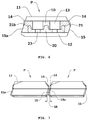
- FIG. 5 is a sectional view of FIG. 3 cut by A-A according to one embodiment of the present invention.
- FIG. 6 is a sectional view of FIG. 3 cut by B-B according to one embodiment of the present invention.
- FIG. 7 is a side view showing that the crawler pads of the present invention are sequentially installed
- FIG. 8 is a perspective view showing a steel core of the crawler pad according to one embodiment of the present invention.
- FIG. 9 is a side view showing a steel core of the crawler pad according to one embodiment of the present invention.
- FIG. 10 is a plan view showing a steel core of the crawler pad according to one embodiment of the present invention.
- FIG. 11 is a bottom view showing a steel core of the crawler pad according to one embodiment of the present invention.
- FIG. 12 is a sectional view of FIG. 10 cut by C-C according to one embodiment of the present invention.
- FIG. 13 is a sectional view of FIG. 10 cut by D-D according to one embodiment of the present invention.
- FIG. 14 is a right sectional view showing the contact state of a pad body and a steel core of the crawler pad according to one embodiment of the present invention.
- respective steps described in the present invention may be performed otherwise. That is, the respective steps may be performed in a specified order, substantially at the same time, or in reverse order.
- the crawler pad roughly comprises a pad body 10 , a steel core 20 , and a stop bump 14 for preventing foreign materials from entering.
- the pad body 10 of the present invention is made by inserting the steel core 20 into rubber as molding material, and vulcanizing it inside a mold, thereby to integrally form together with the steel core 20 , and comprises a ground contact part 11 , which contacts with the ground, and is protrudingly formed on the upper surface thereof, a link coupling part 12 , which is dently formed on the lower center surface thereof and coupled with a track link connected with endless type, and an installation hole 13 , which is formed between the ground contact parts 11 .
- the steel core 20 as stiffener is installed inside the pad body 10 as above, the rigidity of the rubber-made pad body 10 can be greatly increased, and the steel core 20 has installation holes 23 on its center to communicate with the installation holes 13 of the pad body 10 .
- the crawler pad P can be integrally installed to the track link by making the link coupling part 12 of the crawler pad P face to each other with the track link connected by endless type, and penetrating the installation holes 13 and 23 and the track link by using coupling members so as to be integrally coupled together.
- the crawler pad P of the present invention which comprises the pad body 10 and the steel core 20 as such is installed in the track link connected by endless type, and a plurality of the crawler pads P are sequentially installed as shown in FIG. 7 , and foreign materials are prevented from coming into the space between the crawler pads P.
- the pad body 10 includes a stop bump 14 for preventing foreign materials from entering, which is formed protrudingly on each of the front and back of the ground contact parts 11 .
- the stop bump 14 functions to firstly prevent foreign materials from coming into and between neighboring pad bodies 10 .
- the present invention additionally provides the technology of forming overlap inclines 15 and 15 a on the front and back sides of the pad body 10 respectively which are shaped with inclined downwards, while escaping from the typical shape of the prior arts where the front and back sides of the pad body 10 are formed vertically.
- the overlap inclines 15 and 15 a of one pad body 10 are placed to face with another overlap inclines 15 and 15 a of another neighboring pad body 10 while overlapped inclinedly with each other so as to form an overlap region 16 .
- the stop bump 14 and move downwards but they are secondly prevented from passing into the overlap region 16 , so that foreign materials are completely prevented from coming into and between the pad bodies 10 , and it is prevented the pad body 10 made of rubber from torn apart or broken so as to provide the advantage of greatly enhancing the life time of the crawler pad P.
- the pad body 10 also includes a non-ground contact surface 17 which is formed to be inclined downwards at the back surface of the ground contact part 11 , and functions to decrease the contact space with the ground.
- a non-ground contact surface 17 which is formed to be inclined downwards at the back surface of the ground contact part 11 , and functions to decrease the contact space with the ground.
- the steel core 20 includes reinforcing bumps 21 , 21 a , and 21 b on the front, middle and back of the upper surface of the steel core 20 respectively with upwardly protruded there from along its longitudinal direction in order to reinforce the rigidity of the pad body 10 , instead of forming as typical plane shape.
- the reinforcing bumps 21 , 21 a , and 21 b prevent the plane-shaped steel core 20 from being deflected so as to greatly increase the strength of the steel core 20 , and also function to improve the adhesive force by widening the mutual contact area that the rubber pad body 10 is contacted and bonded with the steel core 20 during manufacturing of the crawler pad P. Furthermore, the reinforcing bumps 21 , 21 a , and 21 b provide the effective result of inducing flowed rubber during vulcanizing process to be flowed well through the spaces between the reinforcing bumps 21 , 21 a , and 21 b along them so that the entire external surface of the steel core 20 can be contacted with the pad body 10 thoroughly.
- the reinforcing bump 21 a located at the center further includes a rubber path 22 with dented in order to facilitate the flowed rubber and air during injection molding process of the pad body 10 to well flow through all spaces overall between the reinforcing bumps 21 , 21 a , and 21 b in order to improve flow ability, which provides results of preventing the flowed rubber from collected locally and the effects of improving the integrity of the pad body 10 and the steel core 20 , so as to eventually allow manufacturing of high-qualified crawler pads P.
- a warp prevention sill 27 is additionally formed on the upper end surface of each of the reinforcing bumps 21 , 21 a , and 21 b with protruded there from, so as to further improve the strength of the steel core 20 as well as the strength improvement of the steel core 20 by the reinforcing bumps 21 , 21 a , and 21 b.
- the steel core 20 is formed such that a central part 24 with the installation holes 23 is formed with equal thickness, but edge reinforcing parts 25 are formed on both sides of the central part 24 and the thicknesses of the edge reinforcing parts 25 are gradually greater further going upwardly toward both end sides.
- the portion of the pad body 10 contacted with the rubber thickness enlargement 26 provides special effects of maximizing buffering and increasing good ride even when the apparatus is inclined toward one side during rotation operation because the rubber thickness at the portion of the pad body 10 contacted with the rubber thickness enlargement 26 is enlarged compared with the bonded portions at the centers of the reinforcing bumps 21 , 21 a , and 21 b , and thus the cushion ability at the portion can be further improved, thereby providing higher stability at the operation of the apparatus.
Landscapes
- Engineering & Computer Science (AREA)
- Chemical & Material Sciences (AREA)
- Combustion & Propulsion (AREA)
- Transportation (AREA)
- Mechanical Engineering (AREA)
- Railway Tracks (AREA)
- Heating, Cooling, Or Curing Plastics Or The Like In General (AREA)
Abstract
Description
Claims (1)
Applications Claiming Priority (2)
| Application Number | Priority Date | Filing Date | Title |
|---|---|---|---|
| KR1020170099634A KR101818732B1 (en) | 2017-08-07 | 2017-08-07 | Crawler pad with improved durability |
| KR10-2017-0099634 | 2017-08-07 |
Publications (2)
| Publication Number | Publication Date |
|---|---|
| US20190039665A1 US20190039665A1 (en) | 2019-02-07 |
| US10787211B2 true US10787211B2 (en) | 2020-09-29 |
Family
ID=61001316
Family Applications (1)
| Application Number | Title | Priority Date | Filing Date |
|---|---|---|---|
| US15/945,104 Active 2039-01-22 US10787211B2 (en) | 2017-08-07 | 2018-04-04 | Crawler pad with improved durability |
Country Status (4)
| Country | Link |
|---|---|
| US (1) | US10787211B2 (en) |
| EP (1) | EP3441290B1 (en) |
| JP (1) | JP6665973B2 (en) |
| KR (1) | KR101818732B1 (en) |
Cited By (1)
| Publication number | Priority date | Publication date | Assignee | Title |
|---|---|---|---|---|
| US20240025498A1 (en) * | 2022-07-21 | 2024-01-25 | Transportation Ip Holdings, Llc | Vehicle track pad assembly |
Families Citing this family (1)
| Publication number | Priority date | Publication date | Assignee | Title |
|---|---|---|---|---|
| KR102528060B1 (en) * | 2021-06-16 | 2023-05-04 | 동일고무벨트주식회사 | Rubber pad for steel track |
Citations (10)
| Publication number | Priority date | Publication date | Assignee | Title |
|---|---|---|---|---|
| US4094557A (en) * | 1976-10-18 | 1978-06-13 | J. I. Case Company | Combination low ground pressure, low turning resistance and self-cleaning track shoe |
| US4588233A (en) * | 1984-01-27 | 1986-05-13 | Denbesten Leroy E | Padded rail plate for tracked vehicles |
| JPH07144667A (en) | 1993-11-23 | 1995-06-06 | Bridgestone Corp | Crawler belt rubber shoe |
| US5630657A (en) * | 1993-11-20 | 1997-05-20 | Bridgestone Corporation | Crawler |
| US5800026A (en) * | 1994-06-01 | 1998-09-01 | Komatsu Ltd. | Elastic-bodied crawler plate and crawler band |
| US20030102715A1 (en) * | 1997-09-05 | 2003-06-05 | Komatsu Limited | Elastic flat tread |
| JP2004066997A (en) | 2002-08-07 | 2004-03-04 | Sumitomo Rubber Ind Ltd | Resilient pad |
| US8011739B2 (en) * | 2006-09-13 | 2011-09-06 | Wirtgen Gmbh | Replaceable wear pad |
| JP2016000574A (en) | 2014-06-11 | 2016-01-07 | 株式会社ブリヂストン | Crawler pad |
| US20170113744A1 (en) * | 2015-10-26 | 2017-04-27 | Bridgestone Corporation | Crawler track shoe core metal, resilient crawler track shoe, and crawler track shoe core metal manufacturing method |
Family Cites Families (8)
| Publication number | Priority date | Publication date | Assignee | Title |
|---|---|---|---|---|
| DE2607981C3 (en) * | 1976-02-27 | 1979-02-01 | Hermann Fehling Tief- Und Kulturbau, 2855 Beverstedt | Floor plate for crawler tracks of caterpillar vehicles |
| JP2002166863A (en) * | 2000-12-04 | 2002-06-11 | Ohtsu Tire & Rubber Co Ltd :The | Crawler belt |
| JP2002234470A (en) * | 2001-02-06 | 2002-08-20 | Hitachi Constr Mach Co Ltd | Simple flat shoe |
| JP2008296742A (en) * | 2007-05-31 | 2008-12-11 | Bridgestone Corp | Rubber pad for crawler |
| JP5210624B2 (en) * | 2007-12-26 | 2013-06-12 | 株式会社ブリヂストン | Track pad elastic pad |
| US20110316330A1 (en) * | 2010-06-23 | 2011-12-29 | Mclaren Group Holdings Pte. Ltd. | Continuous Rubber/Metal Hybrid Track with Replaceable Components |
| US8876227B2 (en) * | 2011-06-30 | 2014-11-04 | Caterpillar Inc. | Mobile machine track shoe |
| JP6012156B2 (en) * | 2011-10-26 | 2016-10-25 | 株式会社ブリヂストン | Track pad |
-
2017
- 2017-08-07 KR KR1020170099634A patent/KR101818732B1/en active Active
-
2018
- 2018-04-04 US US15/945,104 patent/US10787211B2/en active Active
- 2018-04-26 JP JP2018084850A patent/JP6665973B2/en active Active
- 2018-06-19 EP EP18178448.9A patent/EP3441290B1/en active Active
Patent Citations (10)
| Publication number | Priority date | Publication date | Assignee | Title |
|---|---|---|---|---|
| US4094557A (en) * | 1976-10-18 | 1978-06-13 | J. I. Case Company | Combination low ground pressure, low turning resistance and self-cleaning track shoe |
| US4588233A (en) * | 1984-01-27 | 1986-05-13 | Denbesten Leroy E | Padded rail plate for tracked vehicles |
| US5630657A (en) * | 1993-11-20 | 1997-05-20 | Bridgestone Corporation | Crawler |
| JPH07144667A (en) | 1993-11-23 | 1995-06-06 | Bridgestone Corp | Crawler belt rubber shoe |
| US5800026A (en) * | 1994-06-01 | 1998-09-01 | Komatsu Ltd. | Elastic-bodied crawler plate and crawler band |
| US20030102715A1 (en) * | 1997-09-05 | 2003-06-05 | Komatsu Limited | Elastic flat tread |
| JP2004066997A (en) | 2002-08-07 | 2004-03-04 | Sumitomo Rubber Ind Ltd | Resilient pad |
| US8011739B2 (en) * | 2006-09-13 | 2011-09-06 | Wirtgen Gmbh | Replaceable wear pad |
| JP2016000574A (en) | 2014-06-11 | 2016-01-07 | 株式会社ブリヂストン | Crawler pad |
| US20170113744A1 (en) * | 2015-10-26 | 2017-04-27 | Bridgestone Corporation | Crawler track shoe core metal, resilient crawler track shoe, and crawler track shoe core metal manufacturing method |
Cited By (1)
| Publication number | Priority date | Publication date | Assignee | Title |
|---|---|---|---|---|
| US20240025498A1 (en) * | 2022-07-21 | 2024-01-25 | Transportation Ip Holdings, Llc | Vehicle track pad assembly |
Also Published As
| Publication number | Publication date |
|---|---|
| KR101818732B1 (en) | 2018-01-15 |
| EP3441290A1 (en) | 2019-02-13 |
| JP6665973B2 (en) | 2020-03-13 |
| EP3441290B1 (en) | 2020-01-22 |
| US20190039665A1 (en) | 2019-02-07 |
| JP2019031266A (en) | 2019-02-28 |
Similar Documents
| Publication | Publication Date | Title |
|---|---|---|
| JP4069085B2 (en) | Rubber crawler | |
| US20060061212A1 (en) | Rubber crawler track | |
| US5362142A (en) | Combination linkage type rubber crawler | |
| EP2699467B1 (en) | Segmented track and track segment therefor | |
| JP4634398B2 (en) | A crawler belt link chain connecting the crawler belt link structure and the link structure | |
| US10787211B2 (en) | Crawler pad with improved durability | |
| US5403643A (en) | Metallic core of rubber track | |
| US20050104448A1 (en) | Elastic track shoe | |
| CA2532292C (en) | Traction band with improved ground-engaging lugs | |
| KR100383456B1 (en) | Elastomeric Infinite Track and Infinite Track | |
| CA2422481C (en) | Elastomeric traction band with lug reinforcements | |
| JP2591525Y2 (en) | Crawler shoe | |
| US6450593B2 (en) | Elastic crawler shoe for discharging snow | |
| KR100492448B1 (en) | An endless track and a manufacturing method thereof | |
| EP2562067B1 (en) | Metal core for crawler, and rubber crawler | |
| US20100289199A1 (en) | Protective tube for coil spring of vehicle suspension device | |
| JP3318724B2 (en) | Connecting link type rubber track | |
| JP3698280B2 (en) | Rubber crawler | |
| JP4194599B2 (en) | Elastic track | |
| US9834265B2 (en) | Rubber track system | |
| JP4235587B2 (en) | Rubber crawler | |
| JP4481434B2 (en) | Rubber crawler | |
| KR20070067493A (en) | Caterpillar | |
| JP4758270B2 (en) | Rubber crawler | |
| JP2001010554A (en) | Elastic crawler |
Legal Events
| Date | Code | Title | Description |
|---|---|---|---|
| AS | Assignment |
Owner name: TR BELTRACK CO., LTD., KOREA, REPUBLIC OF Free format text: ASSIGNMENT OF ASSIGNORS INTEREST;ASSIGNOR:KIM, WOOJEONG;REEL/FRAME:045434/0927 Effective date: 20180319 |
|
| FEPP | Fee payment procedure |
Free format text: ENTITY STATUS SET TO UNDISCOUNTED (ORIGINAL EVENT CODE: BIG.); ENTITY STATUS OF PATENT OWNER: SMALL ENTITY |
|
| FEPP | Fee payment procedure |
Free format text: ENTITY STATUS SET TO SMALL (ORIGINAL EVENT CODE: SMAL); ENTITY STATUS OF PATENT OWNER: SMALL ENTITY |
|
| STPP | Information on status: patent application and granting procedure in general |
Free format text: DOCKETED NEW CASE - READY FOR EXAMINATION |
|
| STPP | Information on status: patent application and granting procedure in general |
Free format text: NON FINAL ACTION MAILED |
|
| STPP | Information on status: patent application and granting procedure in general |
Free format text: RESPONSE TO NON-FINAL OFFICE ACTION ENTERED AND FORWARDED TO EXAMINER |
|
| STPP | Information on status: patent application and granting procedure in general |
Free format text: NOTICE OF ALLOWANCE MAILED -- APPLICATION RECEIVED IN OFFICE OF PUBLICATIONS |
|
| STPP | Information on status: patent application and granting procedure in general |
Free format text: PUBLICATIONS -- ISSUE FEE PAYMENT RECEIVED |
|
| STCF | Information on status: patent grant |
Free format text: PATENTED CASE |
|
| MAFP | Maintenance fee payment |
Free format text: PAYMENT OF MAINTENANCE FEE, 4TH YR, SMALL ENTITY (ORIGINAL EVENT CODE: M2551); ENTITY STATUS OF PATENT OWNER: SMALL ENTITY Year of fee payment: 4 |