US10784713B2 - Uninterruptible power supply device - Google Patents
Uninterruptible power supply device Download PDFInfo
- Publication number
- US10784713B2 US10784713B2 US16/344,216 US201616344216A US10784713B2 US 10784713 B2 US10784713 B2 US 10784713B2 US 201616344216 A US201616344216 A US 201616344216A US 10784713 B2 US10784713 B2 US 10784713B2
- Authority
- US
- United States
- Prior art keywords
- power
- power supply
- load
- regenerative
- unit
- Prior art date
- Legal status (The legal status is an assumption and is not a legal conclusion. Google has not performed a legal analysis and makes no representation as to the accuracy of the status listed.)
- Active, expires
Links
Images


Classifications
-
- H—ELECTRICITY
- H02—GENERATION; CONVERSION OR DISTRIBUTION OF ELECTRIC POWER
- H02J—ELECTRIC POWER NETWORKS; CIRCUIT ARRANGEMENTS OR SYSTEMS FOR SUPPLYING OR DISTRIBUTING ELECTRIC POWER; SYSTEMS FOR STORING ELECTRIC ENERGY
- H02J9/00—Circuit arrangements for emergency or stand-by power supply, e.g. for emergency lighting
- H02J9/04—Circuit arrangements for emergency or stand-by power supply, e.g. for emergency lighting in which the distribution system is disconnected from the normal source and connected to a standby source
- H02J9/06—Circuit arrangements for emergency or stand-by power supply, e.g. for emergency lighting in which the distribution system is disconnected from the normal source and connected to a standby source with automatic change-over, e.g. UPS systems
- H02J9/061—Circuit arrangements for emergency or stand-by power supply, e.g. for emergency lighting in which the distribution system is disconnected from the normal source and connected to a standby source with automatic change-over, e.g. UPS systems for DC powered loads
-
- H—ELECTRICITY
- H02—GENERATION; CONVERSION OR DISTRIBUTION OF ELECTRIC POWER
- H02J—ELECTRIC POWER NETWORKS; CIRCUIT ARRANGEMENTS OR SYSTEMS FOR SUPPLYING OR DISTRIBUTING ELECTRIC POWER; SYSTEMS FOR STORING ELECTRIC ENERGY
- H02J9/00—Circuit arrangements for emergency or stand-by power supply, e.g. for emergency lighting
- H02J9/04—Circuit arrangements for emergency or stand-by power supply, e.g. for emergency lighting in which the distribution system is disconnected from the normal source and connected to a standby source
- H02J9/06—Circuit arrangements for emergency or stand-by power supply, e.g. for emergency lighting in which the distribution system is disconnected from the normal source and connected to a standby source with automatic change-over, e.g. UPS systems
- H02J9/08—Circuit arrangements for emergency or stand-by power supply, e.g. for emergency lighting in which the distribution system is disconnected from the normal source and connected to a standby source with automatic change-over, e.g. UPS systems requiring starting of a prime-mover
-
- G—PHYSICS
- G06—COMPUTING OR CALCULATING; COUNTING
- G06F—ELECTRIC DIGITAL DATA PROCESSING
- G06F1/00—Details not covered by groups G06F3/00 - G06F13/00 and G06F21/00
- G06F1/26—Power supply means, e.g. regulation thereof
- G06F1/30—Means for acting in the event of power-supply failure or interruption, e.g. power-supply fluctuations
-
- H—ELECTRICITY
- H02—GENERATION; CONVERSION OR DISTRIBUTION OF ELECTRIC POWER
- H02J—ELECTRIC POWER NETWORKS; CIRCUIT ARRANGEMENTS OR SYSTEMS FOR SUPPLYING OR DISTRIBUTING ELECTRIC POWER; SYSTEMS FOR STORING ELECTRIC ENERGY
- H02J9/00—Circuit arrangements for emergency or stand-by power supply, e.g. for emergency lighting
- H02J9/04—Circuit arrangements for emergency or stand-by power supply, e.g. for emergency lighting in which the distribution system is disconnected from the normal source and connected to a standby source
- H02J9/06—Circuit arrangements for emergency or stand-by power supply, e.g. for emergency lighting in which the distribution system is disconnected from the normal source and connected to a standby source with automatic change-over, e.g. UPS systems
- H02J9/062—Circuit arrangements for emergency or stand-by power supply, e.g. for emergency lighting in which the distribution system is disconnected from the normal source and connected to a standby source with automatic change-over, e.g. UPS systems for AC powered loads
-
- H—ELECTRICITY
- H02—GENERATION; CONVERSION OR DISTRIBUTION OF ELECTRIC POWER
- H02P—CONTROL OR REGULATION OF ELECTRIC MOTORS, ELECTRIC GENERATORS OR DYNAMO-ELECTRIC CONVERTERS; CONTROLLING TRANSFORMERS, REACTORS OR CHOKE COILS
- H02P27/00—Arrangements or methods for the control of AC motors characterised by the kind of supply voltage
- H02P27/04—Arrangements or methods for the control of AC motors characterised by the kind of supply voltage using variable-frequency supply voltage, e.g. inverter or converter supply voltage
- H02P27/06—Arrangements or methods for the control of AC motors characterised by the kind of supply voltage using variable-frequency supply voltage, e.g. inverter or converter supply voltage using DC to AC converters or inverters
-
- H—ELECTRICITY
- H02—GENERATION; CONVERSION OR DISTRIBUTION OF ELECTRIC POWER
- H02P—CONTROL OR REGULATION OF ELECTRIC MOTORS, ELECTRIC GENERATORS OR DYNAMO-ELECTRIC CONVERTERS; CONTROLLING TRANSFORMERS, REACTORS OR CHOKE COILS
- H02P3/00—Arrangements for stopping or slowing electric motors, generators, or dynamo-electric converters
-
- H—ELECTRICITY
- H02—GENERATION; CONVERSION OR DISTRIBUTION OF ELECTRIC POWER
- H02J—ELECTRIC POWER NETWORKS; CIRCUIT ARRANGEMENTS OR SYSTEMS FOR SUPPLYING OR DISTRIBUTING ELECTRIC POWER; SYSTEMS FOR STORING ELECTRIC ENERGY
- H02J7/00—Circuit arrangements for charging or discharging batteries or for supplying loads from batteries
- H02J7/34—Parallel operation in networks using both storage and other DC sources, e.g. providing buffering
Definitions
- the present invention relates to an uninterruptible power supply device.
- an uninterruptible power supply device is configured to include a converter for converting alternating current (AC) power into direct current (DC) power, and an inverter for converting DC power into AC power, as described for example in Japanese Patent Laying-Open No. 2012-120407 (PTL 1).
- a power storage device is connected to this uninterruptible power supply device, and DC power is supplied to the uninterruptible power supply device by the power storage device.
- AC power from an AC power supply is converted into DC power in the converter.
- the DC power generated by the converter is supplied to the inverter and the power storage device.
- the inverter converts the DC power from the converter or the power storage device into AC power having a fixed frequency and a fixed voltage, and supplies the AC power to a load.
- the uninterruptible power supply device supplies the AC power to the load in an uninterruptible manner, for a period during which the DC power is stored in the power storage device.
- the uninterruptible power supply device described above when regenerative power is generated in the load and the regenerative power is converted into DC power by the inverter, a DC voltage between the converter and the inverter is increased. Since the converter controls the DC voltage (between the converter and the inverter) within the uninterruptible power supply device to have a fixed value, DC power corresponding to a voltage exceeding the fixed value is converted into AC power by the converter, and is supplied to the AC power supply. In this manner, the regenerative power generated in the load is returned to the AC power supply.
- the present invention has been made to solve the aforementioned problem, and an object thereof is to provide an uninterruptible power supply device capable of suppressing regenerative power generated in a load from returning to an AC power supply when the AC power supply cannot recover the regenerative power.
- an uninterruptible power supply device is configured to supply AC power supplied from an AC power supply to a load which alternately performs power running operation and regenerative operation.
- the uninterruptible power supply device includes an uninterruptible power supply unit, an auxiliary load unit configured to consume regenerative power generated in the load, a switch unit, and a control unit.
- the uninterruptible power supply unit is connected between the AC power supply and the load.
- the auxiliary load unit is connected to an AC bus which connects the uninterruptible power supply unit and the load.
- the switch unit is connected between the AC bus and the auxiliary load unit.
- the control unit is configured to control the uninterruptible power supply unit and the switch unit.
- the control unit turns off the switch unit to supply the AC power from the uninterruptible power supply unit to the load.
- the control unit turns off the switch unit to supply the regenerative power to the AC power supply via the uninterruptible power supply unit.
- the control unit turns on the switch unit to supply the regenerative power to the auxiliary load unit.
- an uninterruptible power supply device capable of suppressing regenerative power generated in a load from returning to an AC power supply when the AC power supply cannot recover the regenerative power.
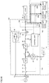
- FIG. 1 is a circuit block diagram showing a configuration of an uninterruptible power supply device in accordance with a first embodiment of the present invention.
- FIG. 2 is a diagram showing a flow of regenerative power in a case where a commercial power supply can recover the regenerative power.
- FIG. 3 is a diagram showing a flow of regenerative power in a case where the commercial power supply cannot recover the regenerative power.
- FIG. 4 is a flowchart for illustrating control performed by a control unit shown in FIG. 1 .
- FIG. 5 is a circuit block diagram showing a configuration of an uninterruptible power supply device in accordance with a second embodiment of the present invention.
- FIG. 6 is a waveform diagram for illustrating control of a switch unit in a control unit shown in FIG. 5 .
- FIG. 7 is a flowchart for illustrating control performed by the control unit shown in FIG. 5 .
- FIG. 8 is a circuit block diagram showing a configuration of an uninterruptible power supply device in accordance with a third embodiment of the present invention.
- FIG. 9 is a diagram showing a flow of regenerative power in a case where a commercial power supply can recover the regenerative power.
- FIG. 10 is a diagram showing a flow of regenerative power in a case where the commercial power supply cannot recover the regenerative power.
- FIG. 11 is a circuit block diagram showing a configuration of an uninterruptible power supply device in accordance with a fourth embodiment of the present invention.
- FIG. 12 is a flowchart for illustrating control performed by a control unit shown in FIG. 11 .
- FIG. 1 is a circuit block diagram showing a configuration of an uninterruptible power supply device 100 in accordance with a first embodiment of the present invention.
- uninterruptible power supply device 100 in accordance with the first embodiment is configured to supply AC power supplied from an AC power supply 1 or a bypass power supply 2 to a load 3 .
- AC power supply 1 is a commercial power supply
- bypass power supply 2 is a private power generator (hereinafter simply referred to as a power generator).
- Commercial power supply 1 supplies AC power having a commercial frequency to uninterruptible power supply device 100 .
- FIG. 1 shows only a circuit for one phase, for simplification of the drawing and the description.
- Load 3 is a motor, for example, and is driven by the AC power supplied from uninterruptible power supply device 100 .
- Load 3 can alternately perform power running operation and regenerative operation.
- Uninterruptible power supply device 100 includes an uninterruptible power supply unit 110 , a switch unit 120 , an auxiliary load unit 130 , an interlock unit 5 , and current detectors 7 and 32 .
- Uninterruptible power supply unit 110 is connected between commercial power supply 1 and load 3 .
- Auxiliary load unit 130 is connected to an AC bus 8 which connects uninterruptible power supply unit 110 and load 3 .
- Switch unit 120 is connected between AC bus 8 and auxiliary load unit 130 .
- Uninterruptible power supply unit 110 includes an input terminal T 1 , an output terminal T 2 , a battery terminal T 3 , and a bypass terminal T 4 .
- Input terminal T 1 receives the AC power supplied from commercial power supply 1 , which is the AC power supply.
- Output terminal T 2 is connected to load 3 via AC bus 8 .
- Load 3 performs the power running operation using the AC power supplied from uninterruptible power supply unit 110 via AC bus 8 .
- Battery terminal T 3 is connected to a battery 4 (power storage device). Instead of battery 4 , a capacitor (such as an electric double layer capacitor or an electrolytic capacitor) may be connected. Battery 4 stores DC power. Bypass terminal T 4 receives the AC power supplied from power generator 2 , which is the bypass power supply.
- a capacitor such as an electric double layer capacitor or an electrolytic capacitor
- Uninterruptible power supply device 100 further includes switches 10 , 22 , and 30 , a fuse 12 , reactors 14 and 26 , a converter 16 , an electrolytic capacitor 18 , a bidirectional chopper 20 , an inverter 24 , a capacitor 28 , a bypass circuit 34 , and a control unit 40 .
- Switch 10 , fuse 12 , reactor 14 , converter 16 , inverter 24 , reactor 26 , and switch 30 are connected in series between input terminal T 1 and output terminal T 2 .
- Switch 10 is connected between input terminal T 1 and converter 16 .
- Switch 10 is closed (turned on) in an ordinary state where the AC power is normally supplied from commercial power supply 1 , and is opened (turned off) during maintenance of uninterruptible power supply unit 110 , for example.
- Fuse 12 is inserted into an energizing path between input terminal T 1 and converter 16 to prevent an overcurrent from flowing from commercial power supply 1 .
- Reactor 14 is provided to pass the AC power from commercial power supply 1 , and to prevent a signal having a switching frequency generated in converter 16 from propagating to commercial power supply 1 .
- Converter 16 is configured such that, when the AC power supplied from commercial power supply 1 is normal, converter 16 converts the AC power into DC power (conversion).
- the DC power generated in converter 16 is output to a DC bus 17 .
- converter 16 outputs a direct current to DC bus 17 such that a DC voltage of DC bus 17 becomes a target DC voltage. That is, converter 16 controls the DC voltage of DC bus 17 to have a fixed value.
- converter 16 is configured such that, when DC power is supplied from inverter 24 via DC bus 17 , converter 16 converts the DC power into AC power having the commercial frequency (inversion). Power conversion in converter 16 is controlled by control unit 40 .
- DC bus 17 is connected to battery terminal T 3 via bidirectional chopper 20 and switch 22 , and is also connected to an input terminal of inverter 24 .
- Electrolytic capacitor 18 is connected to DC bus 17 to smooth the DC voltage of DC bus 17 .
- Switch 22 is turned on during operation of uninterruptible power supply device 100 , and is turned off during maintenance of battery 4 and uninterruptible power supply device 100 .
- Bidirectional chopper 20 is configured to perform bidirectional DC voltage conversion (boost and buck).
- bidirectional chopper 20 stores the DC power generated by converter 16 in battery 4 .
- bidirectional chopper 20 supplies a direct current to battery 4 such that a voltage between terminals of battery 4 (voltage at battery terminal T 3 ) becomes a target battery voltage.
- DC voltage conversion in bidirectional chopper 20 is controlled by control unit 40 .
- inverter 24 converts the DC power generated by converter 16 into AC power having the commercial frequency (inversion).
- inverter 24 converts the DC power supplied from battery 4 via bidirectional chopper 20 into AC power having the commercial frequency.
- Inverter 24 outputs an AC voltage having a phase identical to a phase of an AC voltage supplied from commercial power supply 1 .
- Inverter 24 outputs an alternating current such that an AC voltage at output terminal T 2 becomes a target AC voltage.
- inverter 24 is configured such that, when inverter 24 receives regenerative power from load 3 , inverter 24 converts this regenerative power into DC power (conversion). Power conversion in inverter 24 is controlled by control unit 40 .
- Reactor 26 has one terminal connected to an AC terminal of inverter 24 , and the other terminal connected to output terminal T 2 via switch 30 .
- Capacitor 28 is connected to the other terminal of reactor 26 .
- Reactor 26 and capacitor 28 constitute a filter for removing a component having the switching frequency included in the AC power output from inverter 24 .
- Switch 30 is turned on in a mode in which the AC power is supplied from inverter 24 to load 3 (hereinafter also referred to as a first mode). In contrast, switch 30 is turned off in a mode in which the AC power is supplied from power generator 2 , which is the bypass power supply, to load 3 via bypass circuit 34 (hereinafter also referred to as a second mode). Turning on/off of switch 30 is controlled by control unit 40 .
- Bypass terminal T 4 receives the AC power supplied from power generator 2 .
- Bypass circuit 34 is connected between bypass terminal T 4 and output terminal T 2 .
- Bypass circuit 34 includes a semiconductor switch 36 connected between bypass terminal T 4 and output terminal T 2 , and a switch 38 connected in parallel with semiconductor switch 36 .
- Semiconductor switch 36 is turned on only for a predetermined period, when the first mode is shifted to the second mode, and when the second mode is shifted to the first mode.
- Semiconductor switch 36 includes two thyristors. An anode and a cathode of one thyristor are connected to bypass terminal T 4 and output terminal T 2 , respectively, and an anode and a cathode of the other thyristor are connected to output terminal T 2 and bypass terminal T 4 , respectively.
- Switch 38 is turned off in the first mode, and is turned on in the second mode. Turning on/off of semiconductor switch 36 and switch 38 is controlled by control unit 40 .
- Interlock unit 5 is configured such that, when the bypass power supply is power generator 2 , interlock unit 5 prohibits the regenerative power generated in load 3 from being returned to power generator 2 via bypass circuit 34 . This can prevent power generator 2 from being broken by receiving the regenerative power.
- interlock unit 5 includes an operating unit to be operated by a user or an operator.
- Interlock unit 5 outputs, to control unit 40 , a control command for permitting or prohibiting returning the regenerative power to the bypass power supply, according to the result of operation of the operating unit.
- the user or the operator can set, through the operating unit, whether each of the AC power supply and the bypass power supply is a commercial power supply or a private power generator, when uninterruptible power supply device 100 is installed.
- interlock unit 5 since the bypass power supply is set as the private power generator, interlock unit 5 outputs, to control unit 40 , a control command for prohibiting returning the regenerative power to the bypass power supply.
- Current detector 7 detects an instantaneous value of an alternating current flowing to load 3 (hereinafter also referred to as a load current), and outputs a signal indicating the detection value to control unit 40 .
- Current detector 32 detects an instantaneous value of a current flowing between inverter 24 and output terminal T 2 (hereinafter also referred to as an inverter output current), and outputs a signal indicating the detection value to control unit 40 .
- Control unit 40 determines whether load 3 is performing the power running operation or the regenerative operation, based on the output signal of current detector 7 . Specifically, control unit 40 performs, for example, three-phase to two-phase conversion (for example, dq conversion) on a three-phase AC current obtained from the output signal of current detector 7 , to obtain an active current and a reactive current. When the active current has a positive value (that is, when the active current is flowing into load 3 ), control unit 40 determines that load 3 is performing the power running operation. In contrast, when the active current has a negative value (that is, when the active current is flowing out of load 3 ), control unit 40 determines that load 3 is performing the regenerative operation.
- three-phase to two-phase conversion for example, dq conversion
- control unit 40 controls turning on/off of switches 10 , 22 , 30 and bypass circuit 34 and power conversion in converter 16 and inverter 24 , such that uninterruptible power supply unit 110 selectively performs the first mode and the second mode.
- control unit 40 controls power conversion in converter 16 and inverter 24 to supply the regenerative power to commercial power supply 1 via uninterruptible power supply unit 110 .
- control unit 40 causes auxiliary load unit 130 to consume the regenerative power, as described later.
- Auxiliary load unit 130 has at least one auxiliary load 6 .
- auxiliary load unit 130 has one auxiliary load 6 .
- Auxiliary load 6 is used to consume the regenerative power generated in load 3 .
- auxiliary load 6 includes a resistive element or an inductor element. The resistive element (or inductor element) has one terminal electrically connected to AC bus 8 , and the other terminal electrically connected to a grounding wire not shown.
- Switch unit 120 has at least one switch SW.
- switch unit 120 has one switch SW.
- switch SW is a contactor.
- Switch SW has one terminal connected to AC bus 8 , and the other terminal connected to auxiliary load 6 . Turning on/off of switch SW is controlled by control unit 40 .
- uninterruptible power supply device 100 in accordance with the first embodiment will be described.
- switch 30 is turned on and inverter 24 and output terminal T 2 are electrically connected, whereas bypass circuit 34 is turned off and bypass terminal T 4 and output terminal T 2 are electrically disconnected.
- control unit 40 determines based on an output signal of current detector 7 that load 3 is performing the power running operation, control unit 40 causes uninterruptible power supply unit 110 to perform the first mode.
- the AC power from commercial power supply 1 is supplied to converter 16 via switch 10 , fuse 12 , and reactor 14 , and is converted into DC power by converter 16 .
- the DC power generated by converter 16 is stored in battery 4 via bidirectional chopper 20 and switch 22 .
- Inverter 24 converts the DC power generated by converter 16 into AC power.
- Load 3 receives the AC power supplied from commercial power supply 1 and performs the power running operation.
- the AC power generated by inverter 24 is supplied to load 3 via reactor 26 and switch 30 .
- the voltage between the terminals of battery 4 decreases to reach a discharge cutoff voltage, operation of bidirectional chopper 20 and inverter 24 is stopped.
- bypass circuit 34 is turned on and bypass terminal T 4 and output terminal T 2 are electrically connected, whereas switch 30 is turned off and inverter 24 and output terminal T 2 are electrically disconnected.
- control unit 40 determines based on an output signal of current detector 7 that load 3 is performing power running operation, control unit 40 causes uninterruptible power supply unit 110 to perform the second mode.
- the second mode when AC power is normally supplied from power generator 2 , the AC power from power generator 2 is supplied to load 3 via bypass circuit 34 .
- Load 3 receives the AC power supplied from power generator 2 and performs the power running operation.
- the second mode is switched to the first mode.
- the DC power in battery 4 is converted into AC power by inverter 24 , and is supplied to load 3 . Therefore, even when an abnormality occurs in power generator 2 , it is possible to continue the power running operation of load 3 for a period during which the DC power is stored in battery 4 .
- control unit 40 determines based on an output signal of current detector 7 that load 3 is performing the regenerative operation, control unit 40 then determines whether or not at least one of the AC power supply and the bypass power supply can recover the regenerative power.
- control unit 40 determines whether or not commercial power supply 1 , which is the AC power supply, can recover the regenerative power.
- control unit 40 detects an abnormality in commercial power supply 1 by monitoring an AC voltage supplied from commercial power supply 1 to input terminal T 1 . For example, during a power failure in commercial power supply 1 , an effective value of the AC voltage supplied from commercial power supply 1 abnormally decreases. Control unit 40 detects based on the decrease of the AC voltage that the AC power from commercial power supply 1 becomes abnormal. When the AC power from commercial power supply 1 becomes abnormal, control unit 40 determines that commercial power supply 1 cannot recover the regenerative power.
- control unit 40 determines that commercial power supply 1 can recover the regenerative power. Based on the determined result, control unit 40 processes the regenerative power generated in load 3 , by performing operation according to the following description.
- FIG. 2 is a diagram showing a flow of regenerative power in a case where commercial power supply 1 can recover the regenerative power.
- the flow of the regenerative power is indicated by an arrow.
- control unit 40 When load 3 is performing the regenerative operation, control unit 40 turns on switches 10 , 22 , and 30 , and turns off switch SW. Output terminal T 2 of uninterruptible power supply unit 110 receives the regenerative power generated in load 3 .
- inverter 24 converts the regenerative power supplied from output terminal T 2 into DC power (conversion).
- Converter 16 converts the DC power generated by inverter 24 into AC power in synchronization with the commercial frequency (inversion).
- the AC power generated by converter 16 is output from input terminal T 1 and is supplied to commercial power supply 1 .
- Conversion in inverter 24 and inversion in converter 16 are controlled by control unit 40 .
- FIG. 3 is a diagram showing a flow of regenerative power in a case where commercial power supply 1 cannot recover the regenerative power.
- the flow of the regenerative power is indicated by an arrow.
- control unit 40 determines that load 3 is performing the regenerative operation
- control unit 40 turns on switch SW of switch unit 120 .
- the regenerative power is not supplied to output terminal T 2 of uninterruptible power supply unit 110 , but is supplied to auxiliary load unit 130 .
- Control unit 40 causes auxiliary load 6 to consume the regenerative power. In this case, operation of inverter 24 and converter 16 is stopped.
- control unit 40 When load 3 switches from the regenerative operation to the power running operation, control unit 40 turns off switch SW to electrically disconnect auxiliary load 6 from AC bus 8 .
- control unit 40 turns off switch SW to electrically disconnect auxiliary load 6 from AC bus 8 .
- FIG. 4 is a flowchart for illustrating control performed by control unit 40 shown in FIG. 1 .
- the flowchart in FIG. 4 shows control performed by control unit 40 in the first mode. Processing in the flowchart in FIG. 4 is invoked from a main routine and performed at regular time intervals or whenever predetermined conditions are satisfied.
- control unit 40 determines whether or not load 3 is performing regenerative operation, based on an output signal of current detector 7 .
- load 3 is not performing regenerative operation, i.e., when load 3 is performing power running operation (NO in S 02 )
- control unit 40 proceeds to step S 02 , and determines whether or not AC power from commercial power supply 1 is normal.
- step S 03 control unit 40 turns off switch SW of switch unit 120 .
- step S 04 converter 16 converts the AC power from commercial power supply 1 into DC power.
- the DC power generated by converter 16 is stored in battery 4 via bidirectional chopper 20 and switch 22 .
- Inverter 24 converts the DC power generated by converter 16 into AC power.
- Control unit 40 controls conversion in converter 16 and inversion in inverter 24 .
- load 3 receives the AC power supplied from commercial power supply 1 and performs the power running operation.
- step S 05 control unit 40 turns off switch SW of switch unit 120 .
- step S 06 inverter 24 converts the DC power stored in battery 4 into AC power. On this occasion, operation of converter 16 is stopped.
- Control unit 40 controls inversion in inverter 24 . Thereby, load 3 receives power supply from battery 4 and performs the power running operation.
- control unit 40 proceeds to step S 07 , and determines whether or not the AC power from commercial power supply 1 is normal.
- step S 08 control unit 40 turns off switch SW of switch unit 120 .
- inverter 24 converts regenerative power generated in load 3 into DC power (conversion).
- Converter 16 converts the DC power generated by inverter 24 into AC power (inversion).
- Control unit 40 controls conversion in inverter 24 and inversion in converter 16 . Thereby, the regenerative power generated in load 3 is returned to commercial power supply 1 .
- control unit 40 proceeds to step S 10 , and turns on switch SW of switch unit 120 . Thereby, the regenerative power is supplied to auxiliary load 6 .
- control unit 40 causes auxiliary load 6 to consume the regenerative power.
- control unit 40 stops operation of inverter 24 and converter 16 .
- the uninterruptible power supply device in accordance with the first embodiment of the present invention, during the regenerative operation of load 3 , in a case where the AC power supply and the bypass power supply cannot recover the regenerative power generated in load 3 , the regenerative power is consumed by auxiliary load unit 130 .
- Such a configuration can suppress the regenerative power from returning to the AC power supply and the bypass power supply, and thus can suppress an increase in the DC voltage of DC bus 17 . This can prevent a situation where DC bus 17 has an overvoltage and thereby converter 16 and inverter 24 are stopped for overvoltage protection.
- FIG. 5 is a circuit block diagram showing a configuration of uninterruptible power supply device 100 in accordance with a second embodiment of the present invention.
- the uninterruptible power supply device in accordance with the second embodiment is different from uninterruptible power supply device 100 in accordance with the first embodiment shown in FIG. 1 in that auxiliary load unit 130 includes a plurality of auxiliary loads 61 to 63 and switch unit 120 includes a plurality of switches SW 1 to SW 3 .
- auxiliary load unit 130 includes a plurality of auxiliary loads 61 to 63
- switch unit 120 includes a plurality of switches SW 1 to SW 3 .
- the number of auxiliary loads and the number of switches are set to three in the example in FIG. 5 , the number of auxiliary loads and the number of switches may be set to two, or may be set to four or more.
- Each of auxiliary loads 61 to 63 includes a resistive element or an inductor element.
- Each resistive element or inductor element has one terminal electrically connected to AC bus 8 , and the other terminal electrically connected to a grounding wire not shown.
- Switches SW 1 to SW 3 are connected between AC bus 8 and auxiliary loads 61 to 63 , respectively.
- switch SW 1 has one terminal electrically connected to AC bus 8 , and the other terminal electrically connected to auxiliary load 61 .
- Switch SW 2 has one terminal electrically connected to AC bus 8 , and the other terminal electrically connected to auxiliary load 62 .
- Switch SW 3 has one terminal electrically connected to AC bus 8 , and the other terminal electrically connected to auxiliary load 63 .
- each of switches SW 1 to SW 3 is a contactor.
- the plurality of auxiliary loads 61 to 63 are connected in parallel with each other with respect to AC bus 8 , via switches SW 1 to SW 3 , respectively. Turning on/off of switches SW 1 to SW 3 is controlled by control unit 40 .
- uninterruptible power supply device 100 in accordance with the second embodiment operation in a case where load 3 is performing power running operation, and operation in a case where load 3 is performing regenerative operation and commercial power supply 1 can recover regenerative power (that is, AC power is normally supplied from commercial power supply 1 ) are the same as those in uninterruptible power supply device 100 in accordance with the first embodiment, and thus the description thereof will not be repeated. In the following, a description will be given on operation in a case where load 3 is performing regenerative operation and commercial power supply 1 cannot recover regenerative power.
- FIG. 5 Using FIG. 5 , a flow of regenerative power in a case where commercial power supply 1 cannot recover the regenerative power will be described.
- the flow of the regenerative power is indicated by arrows.
- control unit 40 determines that load 3 is performing the regenerative operation, control unit 40 turns on switches SW 1 to SW 3 of switch unit 120 . Specifically, while the regenerative power is increasing, control unit 40 sequentially turns on switches SW 1 to SW 3 . Further, while the regenerative power is decreasing, control unit 40 sequentially turns off switches SW 1 to SW 3 . Control unit 40 can equalize the regenerative power generated in load 3 with the power consumption in entire auxiliary load unit 130 , by controlling turning on/off of switches SW 1 to SW 3 based on the magnitude of the regenerative power.
- FIG. 6 is a waveform diagram for illustrating control of switch unit 120 in control unit 40 .
- power W 1 indicates input/output power of load 3 (hereinafter also referred to as load power).
- Control unit 40 can calculate load power W 1 based on a load current detected by current detector 7 and a voltage of AC bus 8 .
- load power W 1 its power value during the power running operation of load 3 is indicated by a positive value, and its power value during the regenerative operation of load 3 is indicated by a negative value.
- Power W 2 indicates input/output power of uninterruptible power supply unit 110 (hereinafter also referred to as UPS power).
- Control unit 40 can calculate UPS power W 2 based on an inverter output current detected by current detector 32 and the voltage of AC bus 8 .
- UPS power W 2 its power value during power output to AC bus 8 is indicated by a positive value, and its power value during power input from AC bus 8 is indicated by a negative value.
- Power W 3 indicates input/output power of battery 4 (hereinafter also referred to as battery power).
- Control unit 40 can calculate battery power W 3 based on a current flowing to battery 4 and a voltage between the terminals of battery 4 .
- battery power W 3 its power value during discharging of battery 4 is indicated by a positive value, and its power value during charging of battery 4 is indicated by a negative value.
- Power W 4 indicates input/output power of commercial power supply 1 (hereinafter also referred to as power supply power).
- Control unit 40 can calculate power supply power W 4 based on a current flowing to input terminal T 1 and a voltage at input terminal T 1 .
- power supply power W 4 its power value during power supply to uninterruptible power supply unit 110 is indicated by a positive value, and its power value during power recovery from uninterruptible power supply unit 110 is indicated by a negative value.
- load 3 performs the power running operation for a time period from a time point t 0 to a time point t 1 and a time period after a time point t 6 , and performs the regenerative operation for a time period from time point t 1 to time point t 6 .
- control unit 40 When load 3 switches from the power running operation to the regenerative operation at time point t 1 , control unit 40 first turns on one switch SW 1 of switches SW 1 to SW 3 . While the magnitude (corresponding to the absolute value) of load power W 1 is increasing after time point t 1 , control unit 40 sequentially turns on remaining switches SW 2 and SW 3 .
- control unit 40 has three threshold values WB 1 , WB 2 , and WB 3 for controlling turning on/off of switches SW 1 to SW 3 .
- First threshold value WB 1 has the largest absolute value
- third threshold value WB 3 has the largest absolute value (
- control unit 40 When load power W 1 is more than second threshold value WB 2 and is less than or equal to first threshold value WB 1 (WB 2 ⁇ W 1 ⁇ WB 1 ), control unit 40 turns on switch SW 1 .
- load power W 1 is more than third threshold value WB 3 and is less than or equal to second threshold value WB 2 (WB 3 ⁇ W 1 ⁇ WB 2 )
- control unit 40 turns on switches SW 1 and SW 2 .
- load power W 1 is less than or equal to third threshold value WB 3 (W 1 ⁇ WB 3 )
- control unit 40 turns on switches SW 1 to SW 3 .
- switch SW 1 is turned on at time point t 1
- switch SW 2 is further turned on at time point t 2 later than time point t 1
- switch SW 3 is further turned on at time point t 3 later than time point t 2 . That is, switches SW 1 to SW 3 are sequentially turned on as the magnitude of the regenerative power increases.
- auxiliary load unit 130 When the power consumption in auxiliary load unit 130 becomes larger than the regenerative power, uninterruptible power supply unit 110 compensates for a deficiency in the power consumption, and the power stored in battery 4 may be consumed wastefully.
- power extraction from battery 4 can be prevented by equalizing the regenerative power with the power consumption in auxiliary load unit 130 .
- UPS power W 2 and battery power W 3 temporarily increase at timing at which each of switches SW 1 to SW 3 is turned on (corresponding to time points t 1 , t 2 , t 3 ). This is because a state where the power consumption in auxiliary load unit 130 becomes larger than load power W 1 (regenerative power) temporarily occurs at timing at which switch SW is turned on.
- load power W 1 regenerative power
- UPS power W 2 covers power corresponding to a difference between W 1 and WC 1 .
- UPS power W 2 and battery power W 3 temporarily increase.
- UPS power W 2 covers power corresponding to a difference between W 1 and (WC 1 +WC 2 ), and thus UPS power W 2 and battery power W 3 temporarily increase.
- UPS power W 2 decreases toward 0, and thus power extraction from battery 4 does not occur.
- control unit 40 sequentially turns off switches SW 1 to SW 3 . Specifically, when load power W 1 becomes more than third threshold value WB 3 and less than or equal to second threshold value WB 2 , control unit 40 turns off switch SW 3 . When load power W 1 becomes more than second threshold value WB 2 and less than or equal to first threshold value WB 1 , control unit 40 turns off switches SW 2 and SW 3 . When load power W 1 becomes more than first threshold value WB 1 , control unit 40 turns off switches SW 1 to SW 3 .
- switch SW 3 is turned off at time point t 4 , then switch SW 2 is further turned off at time point t 5 later than time point t 4 , and then switch SW 1 is further turned off at time point t 6 later than time point t 5 . That is, switches SW 1 to SW 3 are sequentially turned off as the magnitude of the regenerative power decreases.
- auxiliary load unit 130 when the power consumption in auxiliary load unit 130 becomes larger than the regenerative power, uninterruptible power supply unit 110 compensates for a deficiency in the power consumption, and the power stored in battery 4 may be consumed wastefully.
- the third embodiment even while the regenerative power is decreasing, the power having a magnitude equal to that of the regenerative power is consumed in auxiliary load unit 130 . Therefore, power extraction from battery 4 can be prevented.
- FIG. 7 is a flowchart for illustrating control performed by control unit 40 shown in FIG. 5 . Processing in this flowchart is invoked from a main routine and performed at regular time intervals or whenever predetermined conditions are satisfied.
- FIG. 7 includes processing in steps S 13 to S 21 , instead of the processing in steps S 08 to S 12 in the flowchart shown in FIG. 4 . It should be noted that FIG. 7 does not show processing in steps S 02 to S 06 which is common to that in FIG. 4 .
- control unit 40 proceeds to step S 13 and turns off switches SW 1 to SW 3 of switch unit 120 .
- inverter 24 converts regenerative power generated in load 3 into DC power.
- Converter 16 converts the DC power generated by inverter 24 into AC power.
- Control unit 40 controls conversion in inverter 24 and inversion in converter 16 . Thereby, the regenerative power generated in load 3 is returned to commercial power supply 1 .
- control unit 40 controls turning on/off of switches SW 1 to SW 3 of switch unit 120 based on load power W 1 (regenerative power). Specifically, in step S 15 , control unit 40 determines whether or not load power W 1 satisfies the relation of WB 2 ⁇ W 1 ⁇ WB 1 . When load power W 1 satisfies the relation in step S 15 (YES in S 15 ), control unit 40 proceeds to step S 16 , and turns on switch SW 1 and turns off switches SW 2 and SW 3 . Thereby, the regenerative power is supplied to auxiliary load 61 . In step S 20 , control unit 40 causes auxiliary load 61 to consume the regenerative power. In step S 21 , control unit 40 stops operation of inverter 24 and converter 16 .
- control unit 40 determines in step S 17 whether or not load power W 1 satisfies the relation of WB 3 ⁇ W 1 ⁇ WB 2 .
- load power W 1 satisfies the relation in step S 17 (YES in S 17 )
- control unit 40 proceeds to step S 18 , and turns on switches SW 1 and SW 2 and turns off switch SW 3 .
- the regenerative power is supplied to auxiliary loads 61 and 62 .
- control unit 40 causes auxiliary loads 61 and 62 to consume the regenerative power.
- control unit 40 When load power W 1 does not satisfy the relation in step S 17 (NO in S 17 ), that is, when load power W 1 satisfies the relation of W 1 ⁇ WB 3 , control unit 40 proceeds to step S 19 , and turns on steps SW 1 to SW 3 . Thereby, the regenerative power is supplied to auxiliary loads 61 to 63 . In this case, in step S 20 , control unit 40 causes auxiliary loads 61 to 63 to consume the regenerative power.
- the uninterruptible power supply device in accordance with the second embodiment of the present invention also in the case where the regenerative power generated in load 3 fluctuates, the regenerative power can be consumed by auxiliary load unit 130 . Therefore, the same effect as that of the uninterruptible power supply device in accordance with the first embodiment can be obtained.
- FIG. 8 is a circuit block diagram showing a configuration of uninterruptible power supply device 100 in accordance with a third embodiment of the present invention, which is compared with FIG. 5 .
- this uninterruptible power supply device 100 is different from uninterruptible power supply device 100 in FIG. 5 in that bypass terminal T 4 receives AC power supplied from an AC power supply, instead of a bypass power supply, and interlock unit 5 is not included.
- an AC power supply is commercial power supply 1 .
- uninterruptible power supply device 100 in accordance with the third embodiment will be described. Since operation in a case where the first mode is selected is the same as that in uninterruptible power supply device 100 in FIG. 5 , a description will be given on operation in a case where the second mode is selected.
- bypass circuit 34 When the second mode is selected, bypass circuit 34 is turned on and bypass terminal T 4 and output terminal T 2 are electrically connected, whereas switch 30 is turned off and inverter 24 and output terminal T 2 are electrically disconnected.
- control unit 40 determines based on an output signal of current detector 7 that load 3 is performing power running operation, control unit 40 causes uninterruptible power supply unit 110 to perform the second mode.
- the second mode is switched to the first mode.
- the DC power in battery 4 is converted into AC power by inverter 24 , and is supplied to load 3 . Therefore, even when an abnormality occurs in commercial power supply 1 , it is possible to continue the power running operation of load 3 for a period during which the DC power is stored in battery 4 .
- control unit 40 determines based on an output signal of current detector 7 that load 3 is performing the regenerative operation, control unit 40 then determines whether or not commercial power supply 1 can recover the regenerative power.
- control unit 40 detects an abnormality in commercial power supply 1 by monitoring an AC voltage supplied from commercial power supply 1 to input terminal T 1 .
- control unit 40 determines that commercial power supply 1 cannot recover the regenerative power.
- control unit 40 determines that commercial power supply 1 can recover the regenerative power. Based on the determined result, control unit 40 processes the regenerative power generated in load 3 , by performing operation according to the following description.
- FIG. 9 is a diagram showing a flow of regenerative power in a case where commercial power supply 1 can recover the regenerative power.
- the flow of the regenerative power is indicated by an arrow.
- control unit 40 When load 3 is performing the regenerative operation, control unit 40 turns on bypass circuit 34 , and turns off switch 30 and switches SW 1 to SW 3 . Output terminal T 2 of uninterruptible power supply unit 110 receives the regenerative power generated in load 3 .
- uninterruptible power supply unit 110 the regenerative power supplied from output terminal T 2 is guided to bypass terminal T 4 via bypass circuit 34 .
- the regenerative power is output from bypass terminal T 4 , and is supplied to commercial power supply 1 .
- FIG. 10 is a diagram showing a flow of regenerative power in a case where commercial power supply 1 cannot recover the regenerative power.
- the flow of the regenerative power is indicated by arrows.
- control unit 40 determines that load 3 is performing the regenerative operation
- control unit 40 turns on switches SW 1 to SW 3 of switch unit 120 .
- Control unit 40 equalizes the regenerative power generated in load 3 with the power consumption in entire auxiliary load unit 130 , by controlling turning on/off of switches SW 1 to SW 3 based on the magnitude of the regenerative power. Since control of turning on/off of switches SW 1 to SW 3 by control unit 40 is the same as that illustrated in FIG. 5 , the detailed description thereof will not be repeated.
- the regenerative power is not supplied to output terminal T 2 of uninterruptible power supply unit 110 , but is supplied to auxiliary load unit 130 .
- Control unit 40 causes auxiliary load unit 130 to consume the regenerative power. In this case, operation of inverter 24 and converter 16 is stopped.
- control unit 40 When load 3 switches from the regenerative operation to the power running operation, control unit 40 turns off switches SW 1 to SW 3 to electrically disconnect auxiliary loads 61 to 63 from AC bus 8 .
- control unit 40 turns off switches SW 1 to SW 3 to electrically disconnect auxiliary loads 61 to 63 from AC bus 8 .
- the same effect as that of the uninterruptible power supply device in accordance with the second embodiment can be obtained. It should be noted that, in the third embodiment, in the case where commercial power supply 1 can recover the AC power, the regenerative power can be efficiently recovered by returning the regenerative power to commercial power supply 1 via bypass circuit 34 .
- FIG. 11 is a circuit block diagram showing a configuration of uninterruptible power supply device 100 in accordance with a fourth embodiment of the present invention, which is compared with FIG. 10 .
- this uninterruptible power supply device 100 is different from uninterruptible power supply device 100 in FIG. 10 in that interlock unit 5 is included.
- an AC power supply is power generator 2 .
- Interlock unit 5 is configured such that, when the AC power supply is power generator 2 , interlock unit 5 prohibits regenerative power generated in load 3 from being returned to power generator 2 . This can prevent power generator 2 from being broken by receiving the regenerative power.
- interlock unit 5 since the AC power supply is set as power generator 2 , interlock unit 5 outputs, to control unit 40 , a control command for prohibiting returning the regenerative power to the AC power supply.
- uninterruptible power supply device 100 in accordance with the fourth embodiment will be described. Since operation in a case where load 3 is performing power running operation is the same as that in uninterruptible power supply device 100 in FIG. 10 , a description will be given on operation in a case where load 3 is performing regenerative operation.
- control unit 40 determines that load 3 is performing the regenerative operation, control unit 40 turns on switches SW 1 to SW 3 of switch unit 120 .
- control unit 40 can equalize the regenerative power generated in load 3 with the power consumption in entire auxiliary load unit 130 , by controlling turning on/off of switches SW 1 to SW 3 based on the magnitude of the regenerative power. Since control of turning on/off of switches SW 1 to SW 3 by control unit 40 is the same as that illustrated in FIG. 5 , the detailed description thereof will not be repeated.
- FIG. 12 is a flowchart for illustrating control performed by control unit 40 shown in FIG. 11 . Processing in this flowchart is invoked from a main routine and performed at regular time intervals or whenever predetermined conditions are satisfied.
- control unit 40 determines whether or not load 3 is performing regenerative operation, based on an output signal of current detector 7 .
- load 3 is not performing regenerative operation, i.e., when load 3 is performing power running operation (NO in S 31 )
- control unit 40 proceeds to step S 32 , and determines whether or not AC power from power generator 2 is normal.
- step S 35 control unit 40 turns off switches SW 1 to SW 3 of switch unit 120 .
- step S 36 converter 16 converts the AC power from commercial power supply 1 into DC power.
- the DC power generated by converter 16 is stored in battery 4 via bidirectional chopper 20 and switch 22 .
- Inverter 24 converts the DC power generated by converter 16 into AC power.
- Control unit 40 controls conversion in converter 16 and inversion in inverter 24 .
- load 3 receives the AC power supplied from commercial power supply 1 and performs the power running operation.
- step S 33 control unit 40 turns off switches SW 1 to SW 3 of switch unit 120 .
- step S 34 inverter 24 converts the DC power stored in battery 4 into AC power. On this occasion, operation of converter 16 is stopped.
- Control unit 40 controls inversion in inverter 24 . Thereby, load 3 receives power supply from battery 4 and performs the power running operation.
- control unit 40 controls turning on/off of switches SW 1 to SW 3 of switch unit 120 based on load power W 1 (regenerative power), by performing processing shown in steps S 15 to S 21 which is identical to that in FIG. 7 .
- the same effect as that of the uninterruptible power supply device in accordance with the second embodiment can be obtained.
- the regenerative power generated in load 3 can be suppressed from being returned to private power generator 2 . Therefore, private power generator 2 can be prevented from being broken.
Landscapes
- Engineering & Computer Science (AREA)
- Power Engineering (AREA)
- Business, Economics & Management (AREA)
- Emergency Management (AREA)
- Theoretical Computer Science (AREA)
- Physics & Mathematics (AREA)
- General Engineering & Computer Science (AREA)
- General Physics & Mathematics (AREA)
- Stand-By Power Supply Arrangements (AREA)
- Inverter Devices (AREA)
- Charge And Discharge Circuits For Batteries Or The Like (AREA)
Abstract
Description
Claims (7)
Applications Claiming Priority (1)
| Application Number | Priority Date | Filing Date | Title |
|---|---|---|---|
| PCT/JP2016/083496 WO2018087876A1 (en) | 2016-11-11 | 2016-11-11 | Uninterruptible power source apparatus |
Publications (2)
| Publication Number | Publication Date |
|---|---|
| US20190334376A1 US20190334376A1 (en) | 2019-10-31 |
| US10784713B2 true US10784713B2 (en) | 2020-09-22 |
Family
ID=61230851
Family Applications (1)
| Application Number | Title | Priority Date | Filing Date |
|---|---|---|---|
| US16/344,216 Active 2036-12-12 US10784713B2 (en) | 2016-11-11 | 2016-11-11 | Uninterruptible power supply device |
Country Status (5)
| Country | Link |
|---|---|
| US (1) | US10784713B2 (en) |
| JP (1) | JPWO2018087876A1 (en) |
| CN (1) | CN109952690A (en) |
| TW (1) | TWI608686B (en) |
| WO (1) | WO2018087876A1 (en) |
Families Citing this family (13)
| Publication number | Priority date | Publication date | Assignee | Title |
|---|---|---|---|---|
| US10291028B2 (en) | 2016-07-29 | 2019-05-14 | Cummins Power Generation Ip, Inc. | Masterless distributed power transfer control |
| JP6608405B2 (en) * | 2017-07-19 | 2019-11-20 | 矢崎総業株式会社 | Voltage conversion unit |
| JP6958287B2 (en) * | 2017-11-24 | 2021-11-02 | トヨタ自動車株式会社 | Power control system and vehicle |
| JP7180112B2 (en) * | 2018-05-15 | 2022-11-30 | 日新電機株式会社 | Uninterruptible power system |
| JP6957621B2 (en) * | 2018-07-23 | 2021-11-02 | 東芝三菱電機産業システム株式会社 | Uninterruptible power system |
| EP3640177A1 (en) * | 2018-10-19 | 2020-04-22 | Otis Elevator Company | Power supply to ac loads during power source failure in elevator system |
| WO2020089972A1 (en) * | 2018-10-29 | 2020-05-07 | 東芝三菱電機産業システム株式会社 | Wind power generation system and power converter |
| CN112970168B (en) * | 2019-06-25 | 2024-04-26 | 东芝三菱电机产业系统株式会社 | Uninterruptible power supply |
| EP3772154A1 (en) * | 2019-07-31 | 2021-02-03 | ABB Schweiz AG | A power supply system, and an uninterruptible power supply including the power supply system |
| JP6933782B1 (en) * | 2020-06-15 | 2021-09-08 | 東芝三菱電機産業システム株式会社 | Power converter |
| JP7350706B2 (en) * | 2020-10-22 | 2023-09-26 | 東芝三菱電機産業システム株式会社 | Uninterruptible power supply system and uninterruptible power supply |
| US11569681B2 (en) * | 2020-12-04 | 2023-01-31 | Infineon Technologies Austria Ag | Bidirectional battery charge-discharge control |
| US11705753B2 (en) * | 2020-12-09 | 2023-07-18 | Schneider Electric It Corporation | Integrated PFC and DC DC converter for dual DC bus for online UPS application |
Citations (8)
| Publication number | Priority date | Publication date | Assignee | Title |
|---|---|---|---|---|
| JPH02303326A (en) | 1989-05-16 | 1990-12-17 | Japan Atom Energy Res Inst | Power system fluctuation suppressing device and method |
| JPH04372538A (en) | 1991-06-20 | 1992-12-25 | Fuji Electric Co Ltd | Power switching circuit of uninterruptible power supply |
| JPH0564378A (en) | 1990-11-20 | 1993-03-12 | Mitsubishi Electric Corp | Uninterruptible power supply device |
| JP2005124249A (en) | 2003-10-14 | 2005-05-12 | Tokyo Electric Power Co Inc:The | Control method and apparatus for uninterruptible power supply with power storage function |
| JP2010124549A (en) | 2008-11-17 | 2010-06-03 | Toshiba Corp | Movable body |
| JP2012120407A (en) | 2010-12-03 | 2012-06-21 | Toshiba Mitsubishi-Electric Industrial System Corp | Uninterruptible power supply |
| US20140021888A1 (en) | 2012-07-17 | 2014-01-23 | Fanuc Corporation | Motor driving device including electric storage device |
| JP2015029396A (en) | 2013-07-31 | 2015-02-12 | 株式会社日立産機システム | Power converter and control method |
Family Cites Families (4)
| Publication number | Priority date | Publication date | Assignee | Title |
|---|---|---|---|---|
| JPH04133633A (en) * | 1990-09-25 | 1992-05-07 | Isao Takahashi | Uninterruptible power unit |
| JP3584686B2 (en) * | 1997-07-31 | 2004-11-04 | 富士電機機器制御株式会社 | Voltage source power conversion circuit |
| JP4588337B2 (en) * | 2004-03-08 | 2010-12-01 | 三菱電機株式会社 | Power converter |
| JP2009124836A (en) * | 2007-11-14 | 2009-06-04 | Fuji Electric Systems Co Ltd | Control unit for uninterruptible power supply system |
-
2016
- 2016-11-11 JP JP2018549708A patent/JPWO2018087876A1/en active Pending
- 2016-11-11 US US16/344,216 patent/US10784713B2/en active Active
- 2016-11-11 CN CN201680090742.5A patent/CN109952690A/en active Pending
- 2016-11-11 WO PCT/JP2016/083496 patent/WO2018087876A1/en not_active Ceased
-
2017
- 2017-01-23 TW TW106102387A patent/TWI608686B/en not_active IP Right Cessation
Patent Citations (9)
| Publication number | Priority date | Publication date | Assignee | Title |
|---|---|---|---|---|
| JPH02303326A (en) | 1989-05-16 | 1990-12-17 | Japan Atom Energy Res Inst | Power system fluctuation suppressing device and method |
| JPH0564378A (en) | 1990-11-20 | 1993-03-12 | Mitsubishi Electric Corp | Uninterruptible power supply device |
| JPH04372538A (en) | 1991-06-20 | 1992-12-25 | Fuji Electric Co Ltd | Power switching circuit of uninterruptible power supply |
| JP2005124249A (en) | 2003-10-14 | 2005-05-12 | Tokyo Electric Power Co Inc:The | Control method and apparatus for uninterruptible power supply with power storage function |
| JP2010124549A (en) | 2008-11-17 | 2010-06-03 | Toshiba Corp | Movable body |
| JP2012120407A (en) | 2010-12-03 | 2012-06-21 | Toshiba Mitsubishi-Electric Industrial System Corp | Uninterruptible power supply |
| US20140021888A1 (en) | 2012-07-17 | 2014-01-23 | Fanuc Corporation | Motor driving device including electric storage device |
| JP2014023241A (en) | 2012-07-17 | 2014-02-03 | Fanuc Ltd | Motor drive device having power storage device |
| JP2015029396A (en) | 2013-07-31 | 2015-02-12 | 株式会社日立産機システム | Power converter and control method |
Non-Patent Citations (1)
| Title |
|---|
| International Search Report dated Jan. 24, 2017 in PCT/JP2016/083496 filed on Nov. 11, 2016. |
Also Published As
| Publication number | Publication date |
|---|---|
| JPWO2018087876A1 (en) | 2019-09-26 |
| WO2018087876A1 (en) | 2018-05-17 |
| US20190334376A1 (en) | 2019-10-31 |
| TWI608686B (en) | 2017-12-11 |
| CN109952690A (en) | 2019-06-28 |
| TW201818633A (en) | 2018-05-16 |
Similar Documents
| Publication | Publication Date | Title |
|---|---|---|
| US10784713B2 (en) | Uninterruptible power supply device | |
| US10811898B2 (en) | Uninterruptible power supply device | |
| EP2814132B1 (en) | Parallel accumulator system and method of control thereof | |
| US11190047B2 (en) | Uninterruptible power supply system including a plurality of uninterruptible power supplies connected in parallel | |
| US11056907B2 (en) | Uninterruptible power supply device | |
| KR101684840B1 (en) | Converter unit system and converter unit | |
| US11258290B2 (en) | Power supply apparatus | |
| AU2013393504A1 (en) | Hybrid drive system | |
| EP3226379B1 (en) | Uninterruptible power supply apparatus | |
| CN100382409C (en) | Non-power cutting power supply system | |
| JP2017184362A (en) | Power conditioner, power supply system, and current control method | |
| JP5289192B2 (en) | Power converter and failure detection method for power converter | |
| EP3168961B1 (en) | Uninterruptible power source device | |
| JP5785316B2 (en) | Power converter | |
| US11271419B2 (en) | Uninterruptible power supply device | |
| JP6468593B2 (en) | Power storage system | |
| JP5819783B2 (en) | Uninterruptible power supply system | |
| KR20160033808A (en) | Power converting apparatus for supplying dc power for dc distributing line | |
| CN110870154A (en) | Power conditioner, power system, and method for suppressing reactive power in power system | |
| KR20180132869A (en) | Uninterruptible power supply | |
| JP6112517B2 (en) | Power conversion device, power supply switching device, house, and power conversion method | |
| JP2017073852A (en) | Power interconnection device for grid connection and control method thereof |
Legal Events
| Date | Code | Title | Description |
|---|---|---|---|
| AS | Assignment |
Owner name: TOSHIBA MITSUBISHI-ELECTRIC INDUSTRIAL SYSTEMS COR Free format text: ASSIGNMENT OF ASSIGNORS INTEREST;ASSIGNOR:TOYODA, MASARU;REEL/FRAME:048971/0672 Effective date: 20190307 Owner name: TOSHIBA MITSUBISHI-ELECTRIC INDUSTRIAL SYSTEMS CORPORATION, JAPAN Free format text: ASSIGNMENT OF ASSIGNORS INTEREST;ASSIGNOR:TOYODA, MASARU;REEL/FRAME:048971/0672 Effective date: 20190307 |
|
| FEPP | Fee payment procedure |
Free format text: ENTITY STATUS SET TO UNDISCOUNTED (ORIGINAL EVENT CODE: BIG.); ENTITY STATUS OF PATENT OWNER: LARGE ENTITY |
|
| STPP | Information on status: patent application and granting procedure in general |
Free format text: NOTICE OF ALLOWANCE MAILED -- APPLICATION RECEIVED IN OFFICE OF PUBLICATIONS |
|
| STPP | Information on status: patent application and granting procedure in general |
Free format text: PUBLICATIONS -- ISSUE FEE PAYMENT VERIFIED |
|
| STCF | Information on status: patent grant |
Free format text: PATENTED CASE |
|
| MAFP | Maintenance fee payment |
Free format text: PAYMENT OF MAINTENANCE FEE, 4TH YEAR, LARGE ENTITY (ORIGINAL EVENT CODE: M1551); ENTITY STATUS OF PATENT OWNER: LARGE ENTITY Year of fee payment: 4 |
|
| AS | Assignment |
Owner name: TMEIC CORPORATION, JAPAN Free format text: CHANGE OF NAME;ASSIGNOR:TOSHIBA MITSUBISHI-ELECTRIC INDUSTRIAL SYSTEMS CORPORATION;REEL/FRAME:067244/0359 Effective date: 20240401 |