US10781983B2 - Courtyard sensor lamp - Google Patents
Courtyard sensor lamp Download PDFInfo
- Publication number
- US10781983B2 US10781983B2 US16/313,210 US201816313210A US10781983B2 US 10781983 B2 US10781983 B2 US 10781983B2 US 201816313210 A US201816313210 A US 201816313210A US 10781983 B2 US10781983 B2 US 10781983B2
- Authority
- US
- United States
- Prior art keywords
- switch module
- courtyard
- lower cover
- connecting portion
- cover
- Prior art date
- Legal status (The legal status is an assumption and is not a legal conclusion. Google has not performed a legal analysis and makes no representation as to the accuracy of the status listed.)
- Active
Links
- 239000000919 ceramic Substances 0.000 claims description 7
- 238000007789 sealing Methods 0.000 claims description 5
- 230000002093 peripheral effect Effects 0.000 claims 1
- 238000010586 diagram Methods 0.000 description 9
- 230000007812 deficiency Effects 0.000 description 2
- 238000005286 illumination Methods 0.000 description 2
- 229920001296 polysiloxane Polymers 0.000 description 2
- 230000000694 effects Effects 0.000 description 1
- 230000007613 environmental effect Effects 0.000 description 1
- 239000011521 glass Substances 0.000 description 1
- 238000012986 modification Methods 0.000 description 1
- 230000004048 modification Effects 0.000 description 1
- 230000003287 optical effect Effects 0.000 description 1
- XLYOFNOQVPJJNP-UHFFFAOYSA-N water Substances O XLYOFNOQVPJJNP-UHFFFAOYSA-N 0.000 description 1
Images


Classifications
-
- F—MECHANICAL ENGINEERING; LIGHTING; HEATING; WEAPONS; BLASTING
- F21—LIGHTING
- F21S—NON-PORTABLE LIGHTING DEVICES; SYSTEMS THEREOF; VEHICLE LIGHTING DEVICES SPECIALLY ADAPTED FOR VEHICLE EXTERIORS
- F21S8/00—Lighting devices intended for fixed installation
-
- F—MECHANICAL ENGINEERING; LIGHTING; HEATING; WEAPONS; BLASTING
- F21—LIGHTING
- F21S—NON-PORTABLE LIGHTING DEVICES; SYSTEMS THEREOF; VEHICLE LIGHTING DEVICES SPECIALLY ADAPTED FOR VEHICLE EXTERIORS
- F21S8/00—Lighting devices intended for fixed installation
- F21S8/03—Lighting devices intended for fixed installation of surface-mounted type
- F21S8/033—Lighting devices intended for fixed installation of surface-mounted type the surface being a wall or like vertical structure, e.g. building facade
- F21S8/036—Lighting devices intended for fixed installation of surface-mounted type the surface being a wall or like vertical structure, e.g. building facade by means of a rigid support, e.g. bracket or arm
-
- F—MECHANICAL ENGINEERING; LIGHTING; HEATING; WEAPONS; BLASTING
- F21—LIGHTING
- F21V—FUNCTIONAL FEATURES OR DETAILS OF LIGHTING DEVICES OR SYSTEMS THEREOF; STRUCTURAL COMBINATIONS OF LIGHTING DEVICES WITH OTHER ARTICLES, NOT OTHERWISE PROVIDED FOR
- F21V15/00—Protecting lighting devices from damage
- F21V15/01—Housings, e.g. material or assembling of housing parts
-
- F—MECHANICAL ENGINEERING; LIGHTING; HEATING; WEAPONS; BLASTING
- F21—LIGHTING
- F21V—FUNCTIONAL FEATURES OR DETAILS OF LIGHTING DEVICES OR SYSTEMS THEREOF; STRUCTURAL COMBINATIONS OF LIGHTING DEVICES WITH OTHER ARTICLES, NOT OTHERWISE PROVIDED FOR
- F21V17/00—Fastening of component parts of lighting devices, e.g. shades, globes, refractors, reflectors, filters, screens, grids or protective cages
- F21V17/10—Fastening of component parts of lighting devices, e.g. shades, globes, refractors, reflectors, filters, screens, grids or protective cages characterised by specific fastening means or way of fastening
-
- F—MECHANICAL ENGINEERING; LIGHTING; HEATING; WEAPONS; BLASTING
- F21—LIGHTING
- F21V—FUNCTIONAL FEATURES OR DETAILS OF LIGHTING DEVICES OR SYSTEMS THEREOF; STRUCTURAL COMBINATIONS OF LIGHTING DEVICES WITH OTHER ARTICLES, NOT OTHERWISE PROVIDED FOR
- F21V23/00—Arrangement of electric circuit elements in or on lighting devices
- F21V23/04—Arrangement of electric circuit elements in or on lighting devices the elements being switches
- F21V23/0442—Arrangement of electric circuit elements in or on lighting devices the elements being switches activated by means of a sensor, e.g. motion or photodetectors
-
- F—MECHANICAL ENGINEERING; LIGHTING; HEATING; WEAPONS; BLASTING
- F21—LIGHTING
- F21V—FUNCTIONAL FEATURES OR DETAILS OF LIGHTING DEVICES OR SYSTEMS THEREOF; STRUCTURAL COMBINATIONS OF LIGHTING DEVICES WITH OTHER ARTICLES, NOT OTHERWISE PROVIDED FOR
- F21V31/00—Gas-tight or water-tight arrangements
-
- F—MECHANICAL ENGINEERING; LIGHTING; HEATING; WEAPONS; BLASTING
- F21—LIGHTING
- F21W—INDEXING SCHEME ASSOCIATED WITH SUBCLASSES F21K, F21L, F21S and F21V, RELATING TO USES OR APPLICATIONS OF LIGHTING DEVICES OR SYSTEMS
- F21W2131/00—Use or application of lighting devices or systems not provided for in codes F21W2102/00-F21W2121/00
- F21W2131/10—Outdoor lighting
- F21W2131/109—Outdoor lighting of gardens
-
- F—MECHANICAL ENGINEERING; LIGHTING; HEATING; WEAPONS; BLASTING
- F21—LIGHTING
- F21Y—INDEXING SCHEME ASSOCIATED WITH SUBCLASSES F21K, F21L, F21S and F21V, RELATING TO THE FORM OR THE KIND OF THE LIGHT SOURCES OR OF THE COLOUR OF THE LIGHT EMITTED
- F21Y2115/00—Light-generating elements of semiconductor light sources
- F21Y2115/10—Light-emitting diodes [LED]
Definitions
- the present disclosure belongs to the technical field of illumination, and more particularly, to a courtyard sensor lamp with a built-in sensor, which is suitable for use in a courtyard.
- a lamp In the field of illumination, a lamp, known as “courtyard sensor lamp” is used for lighting in the interior of the courtyard.
- courtyard sensor lamps such as a courtyard sensor lamp fixed in a courtyard or a flower bed by an upright rod, or a courtyard sensor lamp directly attached to a wall.
- the courtyard sensor lamps used in a house or in a yard is generally controlled to be turned on or turned off separately. That is, it is turned on when needed, and turned off when not needed. Therefore, each courtyard sensor lamp is provided with a switch module which is separately controllable.
- the courtyard sensor lamp is generally in a relatively empty environment (such as road side, flower bed side, or outdoor wall), and a simple external switch module may not only affect the aesthetics of the courtyard sensor lamp, but also have a reduced service life due to a large amount of water flowing into the switch module or light shining directly on the switch module.
- the senor is separable from the switch control module, which is inconvenient for consumers to use and affects the appearance and shape of the lamp body.
- the present disclosure provides a courtyard sensor lamp which is aesthetically pleasing, convenient to use, and safe to use.
- a courtyard sensor lamp which includes a arm, a cover, a light source and a lampshade.
- the arm has a fixed end and a hanging end connected to each other.
- the cover includes an upper cover, a lower cover, a connecting portion and a switch module, the upper cover is connected to the hanging end, the upper cover is rotatably connected to the lower cover, the connecting portion is connected to the upper cover or the lower cover, the connecting portion is provided with a through hole corresponding to the switch module, and the switch module is fixed to a upper portion of the lower cover and disposed in the connecting portion.
- a light source is electrically connected to the switch module.
- the lampshade is fixed below the lower cover and covers the light source.
- the switch module is an integrated lamp sensor and sensor switch control module, and the switch module is controllable by rotation between the upper cover and the lower cover.
- the lamp sensor faces toward the front of the courtyard sensor lamp.
- a control button on the back of the lamp sensor can be showed.
- the lamp sensor is rotated back to an original position, and then the courtyard sensor lamp can operates normally.
- the switch module With the rotation between the upper cover and the lower cover, the switch module can be rotated accordingly to a use position or a hidden position.
- the switch module is hidden to achieve an aesthetically pleasing appearance, and also prevents the switch module from being exposed to the outside environment and being irradiated by sunlight or eroded by wind or rain.
- the connecting portion and the lower cover are fixed to each other, a lower portion of the upper cover is provided with an annular undulating protrusion, and an upper portion of the connecting portion is provided with a groove engaged with the undulating protrusion.
- the groove is an annular groove cooperating with the annular undulating protrusion. There is an interference fit between the undulating projection and the groove.
- a plurality of undulating projections make the structure more compact and the fit more stable.
- the connecting portion and the upper cover are fixed to each other, a lower portion of the connecting portion is provided with a concave step, and the lower cover or the switch module fixed on the lower cover is provided with a boss cooperating with the step.
- the lower cover is connected to the connecting portion by an engaging manner.
- the lower cover is covered in the connecting portion, and the switch module disposed in the lower cover is also covered and hidden by the switch module to prevent the switch module from being exposed to the outside environment and being irradiated by sunlight or eroded by wind or rain.
- an angle of axial rotation between the upper cover and the lower cover is 75° ⁇ 175°.
- the rotation angle is too small, and the control is inconvenient; and when the angle is greater than 175°, the corresponding through hole of the connecting portion is opened larger, and the larger the through hole, the more rain or light entering during the rain or the sun, thereby affecting the service life.
- the larger through hole also affects the aesthetics of the appearance.
- the through hole has a long groove shape formed along the rotation angle.
- the through hole is also a rotation track of the switch module.
- the light source is an incandescent lamp or an LED lamp.
- the light source is fixed inside the lampshade at an upper part of the lampshade by a ceramic lamp holder.
- the ceramic lamp holder and the switch module are connected to each other, and the switch module is connected to the electric supply.
- the switch module includes an infrared sensor and a switch knob electrically connected to each other.
- a sealing element is disposed between the upper cover, the connecting portion and the lower cover.
- the sealing element is a silicone seal.
- the switch module With the axial rotation between the upper cover and the lower cover, the switch module can be rotated to the use position or the hidden position accordingly.
- the switch module is hidden to achieve an aesthetically pleasing appearance, and also prevents the switch module from being exposed to the outside environment and being eroded by the sunlight, wind or rain.
- the lower portion of the upper cover is provided with an annular undulating protrusion
- the upper portion of the connecting portion is provided with a groove engaged with the undulating protrusion.
- the groove is an annular groove cooperates with the annular undulating protrusion. There is an interference fit between the undulating projection and the groove.
- the connecting portion and the upper cover are fixed to each other, the lower portion of the connecting portion is provided with a concave step, and the lower cover or the switch module fixed on the lower cover is provided with a boss cooperating with the step.
- the lower cover is connected to the connecting portion by the engaging manner, the lower cover is covered in the connecting portion, and the switch module disposed in the lower cover is also covered and hidden by the switch module to prevent the switch module from being exposed to the outside environment and being irradiated by sunlight or eroded by wind or rain.
- FIG. 1 is a schematic structural diagram illustrating a courtyard sensor lamp according to an embodiment of the present disclosure.
- FIG. 2 is another schematic structural diagram illustrating a courtyard sensor lamp according to an embodiment of the present disclosure.
- FIG. 3 is a schematic structural diagram illustrating a courtyard sensor lamp according to an embodiment of the present disclosure, before an upper cover and a lower cover are rotated.
- FIG. 4 is a schematic structural diagram illustrating a courtyard sensor lamp according to an embodiment of the present disclosure, after the upper cover and the lower cover has been rotated.
- FIG. 5 is a schematic structural diagram illustrating a courtyard sensor lamp according to an embodiment of the present disclosure, with an upper cover connected to a connecting portion.
- FIG. 6 is a schematic structural diagram illustrating a courtyard sensor lamp according to an embodiment of the present disclosure, with a lower cover connected to a connecting portion.
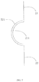
- FIG. 7 is a schematic structural diagram illustrating an undulating protrusion and a groove of a courtyard sensor lamp which cooperate with each other according to an embodiment of the present disclosure.
- a courtyard sensor lamp includes an arm, a cover, a light source 32 and a lampshade 31 .
- the arm has a fixed end 11 and a hanging end 12 connected to each other.
- the fixed end 11 and the hanging end 12 may be integrally formed, or may be separate components that connected to each other.
- the fixed end 11 is provided with a screw hole for being fixed to the wall, and the hanging end 12 extends outward by a certain distance.
- the cover is fixedly suspended from the hanging end 12 , and the cover includes an upper cover 21 and a lower cover 23 rotatably connected to the upper cover 21 by axial rotation, and an angle of axial rotation between the upper cover 21 and the lower cover 23 is 90°.
- FIG. 3 is a schematic diagram before rotation
- FIG. 4 is a schematic diagram after the angle of axial rotation reaching 90°.
- the cover further includes a connecting portion 22 fixedly connected to the upper cover 21 , and a switch module 24 .
- the lower portion of the connecting portion 22 is provided with a concave step
- the lower cover 23 or the switch module 24 fixed on the lower cover 23 is provided with a boss that cooperates with the step.
- FIG. 3 is a schematic diagram before rotation
- FIG. 4 is a schematic diagram after the angle of axial rotation reaching 90°.
- the cover further includes a connecting portion 22 fixedly connected to the upper cover 21 , and a switch module 24 .
- the lower portion of the connecting portion 22 is provided with a concave
- the switch module 24 is fixed to the upper portion of the lower cover 23 and disposed in the connecting portion 22 .
- the connecting portion 22 is provided with a through hole 25 corresponding to the switch module 24 .
- the switch module 24 includes an infrared sensor and a switch knob 241 that are electrically connected to each other.
- the through hole 25 in this embodiment has a long groove shape formed along the rotation angle.
- the through hole 25 is also the rotation track of the switch module 24 .
- a sealing element is disposed between the upper cover, the connecting portion and the lower cover.
- the sealing element is a silicone seal.
- the switch module 24 is an integrated lamp sensor and sensor switch control module, and the switch module is controllable by rotation between the upper cover 21 and the lower cover 24 .
- the lamp sensor faces forward the front of the courtyard sensor lamp.
- a control button on the back of the lamp sensor can be showed.
- the lamp sensor is rotated back to an original position, and then the courtyard sensor lamp can operates normally.
- the lower cover 23 is movably connected to the connecting portion 22 by an engaging manner, and the switch module 24 disposed in the lower cover 23 is simultaneously covered and hidden by the connecting portion 22 to prevent the switch module 24 from being exposed to the outside environment and being irradiated by sunlight or being eroded by wind or rain.
- the switch control of the courtyard sensor lamp can be implemented, which is easy to operate.
- the connecting portion 22 is fixedly connected to the upper cover 21 , and the connecting portion 22 is provided with a through hole 25 .
- the switch module 24 rotates with the lower cover 23 to the use position, the switch module 24 is exposed at the through hole 25 .
- the through hole 25 is used for the switch module 24 to communicate with the outside, which is convenient for the user to operate.
- the switch module 24 is rotated to the hidden position, the switch module 24 is hidden by the connecting portion 22 to achieve an aesthetically pleasing appearance, and also prevents the switch module 24 from being exposed to outside environment and being irradiated by sunlight or being eroded by wind or rain.
- the lampshade 31 is fixed below the lower cover 23 , and the light source 32 is disposed in the lampshade 31 .
- the light source 32 is electrically connected to the switch module 24 .
- the lampshade 31 can be a glass lampshade 31 or a plastic lampshade 31 with good optical transparency, and the light source 32 can be an incandescent lamp or an LED lamp.
- the light source 32 is fixed inside the lampshade 31 at an upper part of the lampshade 31 by a ceramic lamp holder 33 .
- the ceramic lamp cap 33 and the switch module 24 are connected to each other, and the switch module 24 is connected to an electric supply.
- the electric supply can supply electric power to the switch module 24 , and the user can select an infrared sensor switch or a manual switch according to the switch module 24 . After the switch is activated, the electric power is sent to the light source 32 fixedly connected to the ceramic lamp holder 33 through the wire, and light source 32 is turned on.
- the connecting portion 22 and the lower cover 23 are fixed to each other, and the switch module 24 is exposed at the through hole 25 .
- the lower portion of the upper cover 21 is provided with an annular undulating protrusion 211
- an upper portion of the connecting portion 22 is provided with a groove 221 which is engaged with the undulating protrusion 211 .
- the groove 221 is an annular groove 221 cooperating with the annular undulating protrusions 211 .
- An interference fit is formed between the undulating protrusion 211 and the groove 221 .
- the undulating protrusion 211 rotates in an annular shape along the groove 221 , thereby rotating the upper cover 21 and the lower cover 23 to each other.
- the switch module 24 fixed to the connecting portion 22 is rotated to the use position or the hidden position accordingly.
- the use position may be a side of the courtyard sensor lamp that often faces the user.
- the courtyard sensor lamp is provided on the side of the road through which the pedestrian passes in the courtyard, and the use position is the side of the courtyard sensor lamp facing the road, and the hidden position is the side of the courtyard sensor lamp facing away from the road.
- the upper cover 21 When the courtyard sensor lamp is not required to be operated, the upper cover 21 is rotated relative to the lower cover 23 , so that the switch module 24 faces away from the road, and the switch module 24 is not observed by the pedestrian.
- the upper cover 21 can be rotated relative to the lower cover 23 so that the switch module 24 faces the side of the road to facilitate the operation of the courtyard sensor lamp.
- the cooperation between the projection and the groove further prevents the upper cover 21 and the lower cover 23 from falling off during rotation.
- the plurality of undulating protrusions 211 make the structure more compact, and the upper cover 21 and the lower cover 23 are more stable when rotated.
Landscapes
- Engineering & Computer Science (AREA)
- General Engineering & Computer Science (AREA)
- Architecture (AREA)
- Arrangement Of Elements, Cooling, Sealing, Or The Like Of Lighting Devices (AREA)
- Non-Portable Lighting Devices Or Systems Thereof (AREA)
Abstract
Description
Claims (9)
Applications Claiming Priority (4)
| Application Number | Priority Date | Filing Date | Title |
|---|---|---|---|
| CN201720112594.4U CN206530929U (en) | 2017-02-07 | 2017-02-07 | Garden senses lamp |
| CN201720112594U | 2017-02-07 | ||
| CN201720112594.4 | 2017-02-07 | ||
| PCT/CN2018/075298 WO2018145616A1 (en) | 2017-02-07 | 2018-02-05 | Induction garden lamp |
Publications (2)
| Publication Number | Publication Date |
|---|---|
| US20190170308A1 US20190170308A1 (en) | 2019-06-06 |
| US10781983B2 true US10781983B2 (en) | 2020-09-22 |
Family
ID=59916464
Family Applications (1)
| Application Number | Title | Priority Date | Filing Date |
|---|---|---|---|
| US16/313,210 Active US10781983B2 (en) | 2017-02-07 | 2018-02-05 | Courtyard sensor lamp |
Country Status (3)
| Country | Link |
|---|---|
| US (1) | US10781983B2 (en) |
| CN (1) | CN206530929U (en) |
| WO (1) | WO2018145616A1 (en) |
Families Citing this family (5)
| Publication number | Priority date | Publication date | Assignee | Title |
|---|---|---|---|---|
| CN206530929U (en) | 2017-02-07 | 2017-09-29 | 中山和欣灯饰有限公司 | Garden senses lamp |
| USD920561S1 (en) * | 2019-04-17 | 2021-05-25 | Jiawei Renewable Energy Co., Ltd. | Security wall lamp |
| USD912300S1 (en) * | 2019-07-17 | 2021-03-02 | Shenzhen City Sang Leite Photoelectric Limited | LED light |
| USD978406S1 (en) * | 2020-05-22 | 2023-02-14 | Hinkley Lighting, Inc. | Lighting fixture |
| CN114543050B (en) * | 2022-03-18 | 2022-11-15 | 深圳市奥多比科技有限公司 | Rotary LED illuminating lamp for courtyard |
Citations (19)
| Publication number | Priority date | Publication date | Assignee | Title |
|---|---|---|---|---|
| US2246961A (en) * | 1938-03-14 | 1941-06-24 | John F Voogt | Lamp switch mechanism |
| US2278218A (en) * | 1940-01-05 | 1942-03-31 | Line Material Co | Canopy for supporting luminaires |
| US2878373A (en) * | 1955-03-14 | 1959-03-17 | Aladdin Ind Inc | Electric lamp and switch means therefor |
| US3264465A (en) * | 1963-09-03 | 1966-08-02 | Gen Electric | Luminaire |
| US20030053312A1 (en) | 2001-03-23 | 2003-03-20 | Ming-Hua Hung | Built-in lamp apparatus for suspended ceilings |
| US20050200495A1 (en) * | 2004-03-12 | 2005-09-15 | Desa Ip, Llc | Ceiling mount light with 360-degree motion sensor |
| CN2839804Y (en) | 2005-09-28 | 2006-11-22 | 胡振飞 | Charging flashlight |
| US20080278937A1 (en) * | 2007-05-09 | 2008-11-13 | Bono Frank M | Protection shield and grip for flashlight |
| US8434894B2 (en) * | 2009-11-16 | 2013-05-07 | Goal Zero Llc | Lighting apparatus; components thereof and assemblies incorporating the same |
| CN204756603U (en) | 2015-05-28 | 2015-11-11 | 常州市润达照明电器有限公司 | Universal wall lamp |
| CN105135270A (en) | 2015-09-13 | 2015-12-09 | 南京博创工业产品设计有限公司 | Rotating lamp |
| US20160195235A1 (en) * | 2015-01-05 | 2016-07-07 | Goal Zero Llc | Portable lighting device |
| CN205746424U (en) | 2016-04-29 | 2016-11-30 | 朱磊 | A kind of rotatable pendent lamp |
| US20170171932A1 (en) * | 2015-12-15 | 2017-06-15 | Wangs Alliance Corporation | Led lighting methods and apparatus |
| US20170175996A1 (en) * | 2011-11-14 | 2017-06-22 | Tseng-Lu Chien | Light Device has Built-in Digital Data System for Record Image, Sound |
| CN206530929U (en) | 2017-02-07 | 2017-09-29 | 中山和欣灯饰有限公司 | Garden senses lamp |
| US20170307192A1 (en) * | 2016-04-25 | 2017-10-26 | The Pennsylvania Globe Gaslight Company | Extension module with housing for electronic components |
| US20180038583A1 (en) * | 2016-08-04 | 2018-02-08 | Noble Corporation | Lighting fixture |
| US20180128435A1 (en) * | 2016-08-02 | 2018-05-10 | Barebones Systems, Llc | Beacon pendant light |
-
2017
- 2017-02-07 CN CN201720112594.4U patent/CN206530929U/en active Active
-
2018
- 2018-02-05 US US16/313,210 patent/US10781983B2/en active Active
- 2018-02-05 WO PCT/CN2018/075298 patent/WO2018145616A1/en active Application Filing
Patent Citations (19)
| Publication number | Priority date | Publication date | Assignee | Title |
|---|---|---|---|---|
| US2246961A (en) * | 1938-03-14 | 1941-06-24 | John F Voogt | Lamp switch mechanism |
| US2278218A (en) * | 1940-01-05 | 1942-03-31 | Line Material Co | Canopy for supporting luminaires |
| US2878373A (en) * | 1955-03-14 | 1959-03-17 | Aladdin Ind Inc | Electric lamp and switch means therefor |
| US3264465A (en) * | 1963-09-03 | 1966-08-02 | Gen Electric | Luminaire |
| US20030053312A1 (en) | 2001-03-23 | 2003-03-20 | Ming-Hua Hung | Built-in lamp apparatus for suspended ceilings |
| US20050200495A1 (en) * | 2004-03-12 | 2005-09-15 | Desa Ip, Llc | Ceiling mount light with 360-degree motion sensor |
| CN2839804Y (en) | 2005-09-28 | 2006-11-22 | 胡振飞 | Charging flashlight |
| US20080278937A1 (en) * | 2007-05-09 | 2008-11-13 | Bono Frank M | Protection shield and grip for flashlight |
| US8434894B2 (en) * | 2009-11-16 | 2013-05-07 | Goal Zero Llc | Lighting apparatus; components thereof and assemblies incorporating the same |
| US20170175996A1 (en) * | 2011-11-14 | 2017-06-22 | Tseng-Lu Chien | Light Device has Built-in Digital Data System for Record Image, Sound |
| US20160195235A1 (en) * | 2015-01-05 | 2016-07-07 | Goal Zero Llc | Portable lighting device |
| CN204756603U (en) | 2015-05-28 | 2015-11-11 | 常州市润达照明电器有限公司 | Universal wall lamp |
| CN105135270A (en) | 2015-09-13 | 2015-12-09 | 南京博创工业产品设计有限公司 | Rotating lamp |
| US20170171932A1 (en) * | 2015-12-15 | 2017-06-15 | Wangs Alliance Corporation | Led lighting methods and apparatus |
| US20170307192A1 (en) * | 2016-04-25 | 2017-10-26 | The Pennsylvania Globe Gaslight Company | Extension module with housing for electronic components |
| CN205746424U (en) | 2016-04-29 | 2016-11-30 | 朱磊 | A kind of rotatable pendent lamp |
| US20180128435A1 (en) * | 2016-08-02 | 2018-05-10 | Barebones Systems, Llc | Beacon pendant light |
| US20180038583A1 (en) * | 2016-08-04 | 2018-02-08 | Noble Corporation | Lighting fixture |
| CN206530929U (en) | 2017-02-07 | 2017-09-29 | 中山和欣灯饰有限公司 | Garden senses lamp |
Non-Patent Citations (1)
| Title |
|---|
| International Search Report Application No. PCT/CN2018/075298 dated Apr. 28, 2018. |
Also Published As
| Publication number | Publication date |
|---|---|
| CN206530929U (en) | 2017-09-29 |
| US20190170308A1 (en) | 2019-06-06 |
| WO2018145616A1 (en) | 2018-08-16 |
Similar Documents
| Publication | Publication Date | Title |
|---|---|---|
| US10781983B2 (en) | Courtyard sensor lamp | |
| CN113188076A (en) | Intelligent indoor lighting control system | |
| CN202660406U (en) | Double-cap spotlight capable of rotating at multiple angles | |
| CN208703852U (en) | A kind of lamplight brightness adjustable decorative lampshade | |
| CN215569952U (en) | Adjustable anti-dazzle LED wall lamp | |
| US20240041170A1 (en) | Outdoor umbrella with light effect | |
| CN111207327A (en) | Multifunctional garden lamp | |
| CN206112800U (en) | But solar energy lawn lamp that intelligent regulation switch and cell -phone charge | |
| CN205261328U (en) | Double -deck waterproof floodlight down lamp of built -in drive | |
| CN205640280U (en) | Led lamp | |
| CN201860951U (en) | Illumination umbrella | |
| CN212617813U (en) | Multifunctional spot lamp with light diffusion | |
| CN208349176U (en) | A kind of solar energy scenery lamp | |
| CN210345095U (en) | Night illuminating lamp | |
| CN111878723A (en) | Desk lamp capable of intelligently adjusting light according to environmental light sensitivity | |
| CN104633478A (en) | Flashlight | |
| CN210567844U (en) | Lighting rendering and illuminating lamp for indoor design | |
| CN215446282U (en) | Reflector lamp capable of being folded and stored | |
| CN210373204U (en) | Double-function lamp | |
| CN213040499U (en) | Solar support rod lamp | |
| CN213362296U (en) | Flip rotation type solar energy wall lamp | |
| CN213272199U (en) | Take LED garden lamp of intelligence microwave response | |
| CN210153582U (en) | Intelligent LED light-operated lamp | |
| CN215001470U (en) | Freely adjust lamp with memory function | |
| CN210153707U (en) | Can install arbitrary lamp shade and multi-functional solar control system light source module easily |
Legal Events
| Date | Code | Title | Description |
|---|---|---|---|
| AS | Assignment |
Owner name: ZHONGSHAN LITES "R" US CO., LTD., CHINA Free format text: ASSIGNMENT OF ASSIGNORS INTEREST;ASSIGNOR:YEH, LU-SUNG;REEL/FRAME:047981/0093 Effective date: 20181218 |
|
| FEPP | Fee payment procedure |
Free format text: ENTITY STATUS SET TO UNDISCOUNTED (ORIGINAL EVENT CODE: BIG.); ENTITY STATUS OF PATENT OWNER: SMALL ENTITY |
|
| FEPP | Fee payment procedure |
Free format text: ENTITY STATUS SET TO SMALL (ORIGINAL EVENT CODE: SMAL); ENTITY STATUS OF PATENT OWNER: SMALL ENTITY |
|
| STPP | Information on status: patent application and granting procedure in general |
Free format text: DOCKETED NEW CASE - READY FOR EXAMINATION |
|
| STPP | Information on status: patent application and granting procedure in general |
Free format text: NON FINAL ACTION MAILED |
|
| STPP | Information on status: patent application and granting procedure in general |
Free format text: NOTICE OF ALLOWANCE MAILED -- APPLICATION RECEIVED IN OFFICE OF PUBLICATIONS |
|
| STPP | Information on status: patent application and granting procedure in general |
Free format text: PUBLICATIONS -- ISSUE FEE PAYMENT VERIFIED |
|
| STCF | Information on status: patent grant |
Free format text: PATENTED CASE |
|
| MAFP | Maintenance fee payment |
Free format text: PAYMENT OF MAINTENANCE FEE, 4TH YR, SMALL ENTITY (ORIGINAL EVENT CODE: M2551); ENTITY STATUS OF PATENT OWNER: SMALL ENTITY Year of fee payment: 4 |