US10780751B2 - Hitch pin lock systems - Google Patents
Hitch pin lock systems Download PDFInfo
- Publication number
- US10780751B2 US10780751B2 US15/809,154 US201715809154A US10780751B2 US 10780751 B2 US10780751 B2 US 10780751B2 US 201715809154 A US201715809154 A US 201715809154A US 10780751 B2 US10780751 B2 US 10780751B2
- Authority
- US
- United States
- Prior art keywords
- section
- locking member
- channel
- lock rod
- connector
- Prior art date
- Legal status (The legal status is an assumption and is not a legal conclusion. Google has not performed a legal analysis and makes no representation as to the accuracy of the status listed.)
- Active, expires
Links
- 239000000463 material Substances 0.000 claims description 7
- 239000007787 solid Substances 0.000 claims description 6
- 229910052782 aluminium Inorganic materials 0.000 claims description 5
- XAGFODPZIPBFFR-UHFFFAOYSA-N aluminium Chemical compound [Al] XAGFODPZIPBFFR-UHFFFAOYSA-N 0.000 claims description 5
- 230000008878 coupling Effects 0.000 abstract 1
- 238000010168 coupling process Methods 0.000 abstract 1
- 238000005859 coupling reaction Methods 0.000 abstract 1
- -1 etc.) Polymers 0.000 description 7
- 229920001577 copolymer Polymers 0.000 description 3
- 229920000139 polyethylene terephthalate Polymers 0.000 description 3
- 239000005020 polyethylene terephthalate Substances 0.000 description 3
- 229920002943 EPDM rubber Polymers 0.000 description 2
- 229920000181 Ethylene propylene rubber Polymers 0.000 description 2
- PXHVJJICTQNCMI-UHFFFAOYSA-N Nickel Chemical compound [Ni] PXHVJJICTQNCMI-UHFFFAOYSA-N 0.000 description 2
- 239000004698 Polyethylene Substances 0.000 description 2
- 229920002367 Polyisobutene Polymers 0.000 description 2
- 229920001971 elastomer Polymers 0.000 description 2
- 229910052751 metal Inorganic materials 0.000 description 2
- 239000002184 metal Substances 0.000 description 2
- 239000000203 mixture Substances 0.000 description 2
- 229920002239 polyacrylonitrile Polymers 0.000 description 2
- 229920001707 polybutylene terephthalate Polymers 0.000 description 2
- 229920000515 polycarbonate Polymers 0.000 description 2
- 239000004417 polycarbonate Substances 0.000 description 2
- 229920000573 polyethylene Polymers 0.000 description 2
- 229920001721 polyimide Polymers 0.000 description 2
- 229920002959 polymer blend Polymers 0.000 description 2
- 229920005989 resin Polymers 0.000 description 2
- 239000011347 resin Substances 0.000 description 2
- 229920006132 styrene block copolymer Polymers 0.000 description 2
- 239000002023 wood Substances 0.000 description 2
- 229910001369 Brass Inorganic materials 0.000 description 1
- 241001236644 Lavinia Species 0.000 description 1
- 229920002292 Nylon 6 Polymers 0.000 description 1
- 229920002302 Nylon 6,6 Polymers 0.000 description 1
- 239000004642 Polyimide Substances 0.000 description 1
- 239000004743 Polypropylene Substances 0.000 description 1
- 239000004793 Polystyrene Substances 0.000 description 1
- 229910000831 Steel Inorganic materials 0.000 description 1
- 239000004676 acrylonitrile butadiene styrene Substances 0.000 description 1
- 229920001893 acrylonitrile styrene Polymers 0.000 description 1
- 125000003118 aryl group Chemical group 0.000 description 1
- 230000015572 biosynthetic process Effects 0.000 description 1
- 239000010951 brass Substances 0.000 description 1
- MYPDDNAJRRJUCE-UHFFFAOYSA-N buta-1,3-diene;2-methylprop-2-enenitrile;styrene Chemical compound C=CC=C.CC(=C)C#N.C=CC1=CC=CC=C1 MYPDDNAJRRJUCE-UHFFFAOYSA-N 0.000 description 1
- 229920005549 butyl rubber Polymers 0.000 description 1
- 229920002301 cellulose acetate Polymers 0.000 description 1
- 229920006217 cellulose acetate butyrate Polymers 0.000 description 1
- 239000012461 cellulose resin Substances 0.000 description 1
- 239000000919 ceramic Substances 0.000 description 1
- 239000002131 composite material Substances 0.000 description 1
- 239000000806 elastomer Substances 0.000 description 1
- 239000004744 fabric Substances 0.000 description 1
- 229920005555 halobutyl Polymers 0.000 description 1
- 125000004968 halobutyl group Chemical group 0.000 description 1
- 238000010348 incorporation Methods 0.000 description 1
- 150000002739 metals Chemical class 0.000 description 1
- 238000000034 method Methods 0.000 description 1
- 229910052759 nickel Inorganic materials 0.000 description 1
- 230000000149 penetrating effect Effects 0.000 description 1
- 125000005498 phthalate group Chemical group 0.000 description 1
- 229920003023 plastic Polymers 0.000 description 1
- 239000004033 plastic Substances 0.000 description 1
- 229920001084 poly(chloroprene) Polymers 0.000 description 1
- 229920003214 poly(methacrylonitrile) Polymers 0.000 description 1
- 229920003229 poly(methyl methacrylate) Polymers 0.000 description 1
- 229920006122 polyamide resin Polymers 0.000 description 1
- 229920001225 polyester resin Polymers 0.000 description 1
- 239000004645 polyester resin Substances 0.000 description 1
- 229920000120 polyethyl acrylate Polymers 0.000 description 1
- 239000009719 polyimide resin Substances 0.000 description 1
- 229920000193 polymethacrylate Polymers 0.000 description 1
- 239000004926 polymethyl methacrylate Substances 0.000 description 1
- 229920005554 polynitrile Polymers 0.000 description 1
- 229920001155 polypropylene Polymers 0.000 description 1
- 229920002223 polystyrene Polymers 0.000 description 1
- 229920001343 polytetrafluoroethylene Polymers 0.000 description 1
- 239000004810 polytetrafluoroethylene Substances 0.000 description 1
- 229920002635 polyurethane Polymers 0.000 description 1
- 239000004814 polyurethane Substances 0.000 description 1
- SCUZVMOVTVSBLE-UHFFFAOYSA-N prop-2-enenitrile;styrene Chemical compound C=CC#N.C=CC1=CC=CC=C1 SCUZVMOVTVSBLE-UHFFFAOYSA-N 0.000 description 1
- 239000005060 rubber Substances 0.000 description 1
- 229910001220 stainless steel Inorganic materials 0.000 description 1
- 239000010935 stainless steel Substances 0.000 description 1
- 239000010959 steel Substances 0.000 description 1
- 229920003048 styrene butadiene rubber Polymers 0.000 description 1
- 238000010998 test method Methods 0.000 description 1
Images


Classifications
-
- B—PERFORMING OPERATIONS; TRANSPORTING
- B60—VEHICLES IN GENERAL
- B60D—VEHICLE CONNECTIONS
- B60D1/00—Traction couplings; Hitches; Draw-gear; Towing devices
- B60D1/24—Traction couplings; Hitches; Draw-gear; Towing devices characterised by arrangements for particular functions
- B60D1/28—Traction couplings; Hitches; Draw-gear; Towing devices characterised by arrangements for particular functions for preventing unwanted disengagement, e.g. safety appliances
-
- B—PERFORMING OPERATIONS; TRANSPORTING
- B60—VEHICLES IN GENERAL
- B60D—VEHICLE CONNECTIONS
- B60D1/00—Traction couplings; Hitches; Draw-gear; Towing devices
- B60D1/01—Traction couplings or hitches characterised by their type
- B60D1/02—Bolt or shackle-type couplings
- B60D1/025—Bolt or shackle-type couplings comprising release or locking lever pins
-
- B—PERFORMING OPERATIONS; TRANSPORTING
- B60—VEHICLES IN GENERAL
- B60D—VEHICLE CONNECTIONS
- B60D1/00—Traction couplings; Hitches; Draw-gear; Towing devices
- B60D1/58—Auxiliary devices
-
- B—PERFORMING OPERATIONS; TRANSPORTING
- B60—VEHICLES IN GENERAL
- B60D—VEHICLE CONNECTIONS
- B60D1/00—Traction couplings; Hitches; Draw-gear; Towing devices
- B60D1/58—Auxiliary devices
- B60D1/60—Covers, caps or guards, e.g. comprising anti-theft devices
-
- F—MECHANICAL ENGINEERING; LIGHTING; HEATING; WEAPONS; BLASTING
- F16—ENGINEERING ELEMENTS AND UNITS; GENERAL MEASURES FOR PRODUCING AND MAINTAINING EFFECTIVE FUNCTIONING OF MACHINES OR INSTALLATIONS; THERMAL INSULATION IN GENERAL
- F16B—DEVICES FOR FASTENING OR SECURING CONSTRUCTIONAL ELEMENTS OR MACHINE PARTS TOGETHER, e.g. NAILS, BOLTS, CIRCLIPS, CLAMPS, CLIPS OR WEDGES; JOINTS OR JOINTING
- F16B21/00—Means for preventing relative axial movement of a pin, spigot, shaft or the like and a member surrounding it; Stud-and-socket releasable fastenings
- F16B21/10—Means for preventing relative axial movement of a pin, spigot, shaft or the like and a member surrounding it; Stud-and-socket releasable fastenings by separate parts
- F16B21/16—Means for preventing relative axial movement of a pin, spigot, shaft or the like and a member surrounding it; Stud-and-socket releasable fastenings by separate parts with grooves or notches in the pin or shaft
-
- F—MECHANICAL ENGINEERING; LIGHTING; HEATING; WEAPONS; BLASTING
- F16—ENGINEERING ELEMENTS AND UNITS; GENERAL MEASURES FOR PRODUCING AND MAINTAINING EFFECTIVE FUNCTIONING OF MACHINES OR INSTALLATIONS; THERMAL INSULATION IN GENERAL
- F16B—DEVICES FOR FASTENING OR SECURING CONSTRUCTIONAL ELEMENTS OR MACHINE PARTS TOGETHER, e.g. NAILS, BOLTS, CIRCLIPS, CLAMPS, CLIPS OR WEDGES; JOINTS OR JOINTING
- F16B33/00—Features common to bolt and nut
- F16B33/02—Shape of thread; Special thread-forms
-
- F—MECHANICAL ENGINEERING; LIGHTING; HEATING; WEAPONS; BLASTING
- F16—ENGINEERING ELEMENTS AND UNITS; GENERAL MEASURES FOR PRODUCING AND MAINTAINING EFFECTIVE FUNCTIONING OF MACHINES OR INSTALLATIONS; THERMAL INSULATION IN GENERAL
- F16B—DEVICES FOR FASTENING OR SECURING CONSTRUCTIONAL ELEMENTS OR MACHINE PARTS TOGETHER, e.g. NAILS, BOLTS, CIRCLIPS, CLAMPS, CLIPS OR WEDGES; JOINTS OR JOINTING
- F16B35/00—Screw-bolts; Stay-bolts; Screw-threaded studs; Screws; Set screws
- F16B35/04—Screw-bolts; Stay-bolts; Screw-threaded studs; Screws; Set screws with specially-shaped head or shaft in order to fix the bolt on or in an object
- F16B35/041—Specially-shaped shafts
- F16B35/044—Specially-shaped ends
-
- F—MECHANICAL ENGINEERING; LIGHTING; HEATING; WEAPONS; BLASTING
- F16—ENGINEERING ELEMENTS AND UNITS; GENERAL MEASURES FOR PRODUCING AND MAINTAINING EFFECTIVE FUNCTIONING OF MACHINES OR INSTALLATIONS; THERMAL INSULATION IN GENERAL
- F16B—DEVICES FOR FASTENING OR SECURING CONSTRUCTIONAL ELEMENTS OR MACHINE PARTS TOGETHER, e.g. NAILS, BOLTS, CIRCLIPS, CLAMPS, CLIPS OR WEDGES; JOINTS OR JOINTING
- F16B5/00—Joining sheets or plates, e.g. panels, to one another or to strips or bars parallel to them
- F16B5/06—Joining sheets or plates, e.g. panels, to one another or to strips or bars parallel to them by means of clamps or clips
- F16B5/0607—Joining sheets or plates, e.g. panels, to one another or to strips or bars parallel to them by means of clamps or clips joining sheets or plates to each other
- F16B5/0621—Joining sheets or plates, e.g. panels, to one another or to strips or bars parallel to them by means of clamps or clips joining sheets or plates to each other in parallel relationship
- F16B5/065—Joining sheets or plates, e.g. panels, to one another or to strips or bars parallel to them by means of clamps or clips joining sheets or plates to each other in parallel relationship the plates being one on top of the other and distanced from each other, e.g. by using protrusions to keep contact and distance
-
- F—MECHANICAL ENGINEERING; LIGHTING; HEATING; WEAPONS; BLASTING
- F16—ENGINEERING ELEMENTS AND UNITS; GENERAL MEASURES FOR PRODUCING AND MAINTAINING EFFECTIVE FUNCTIONING OF MACHINES OR INSTALLATIONS; THERMAL INSULATION IN GENERAL
- F16B—DEVICES FOR FASTENING OR SECURING CONSTRUCTIONAL ELEMENTS OR MACHINE PARTS TOGETHER, e.g. NAILS, BOLTS, CIRCLIPS, CLAMPS, CLIPS OR WEDGES; JOINTS OR JOINTING
- F16B7/00—Connections of rods or tubes, e.g. of non-circular section, mutually, including resilient connections
- F16B7/18—Connections of rods or tubes, e.g. of non-circular section, mutually, including resilient connections using screw-thread elements
-
- Y—GENERAL TAGGING OF NEW TECHNOLOGICAL DEVELOPMENTS; GENERAL TAGGING OF CROSS-SECTIONAL TECHNOLOGIES SPANNING OVER SEVERAL SECTIONS OF THE IPC; TECHNICAL SUBJECTS COVERED BY FORMER USPC CROSS-REFERENCE ART COLLECTIONS [XRACs] AND DIGESTS
- Y10—TECHNICAL SUBJECTS COVERED BY FORMER USPC
- Y10T—TECHNICAL SUBJECTS COVERED BY FORMER US CLASSIFICATION
- Y10T24/00—Buckles, buttons, clasps, etc.
- Y10T24/45—Separable-fastener or required component thereof [e.g., projection and cavity to complete interlock]
- Y10T24/45225—Separable-fastener or required component thereof [e.g., projection and cavity to complete interlock] including member having distinct formations and mating member selectively interlocking therewith
- Y10T24/45262—Pin, post and receiver
Definitions
- Embodiments described generally relate to hitch pin lock systems. More particularly, such embodiments relate to hitch basket and hitch trailer connectors and locks.
- Hitch pin locks are intended to secure objects such as a hitch basket or trailer to a vehicle. These locks are typically straight metal rods that are inserted into a cylindrical lock.
- FIG. 1 depicts an expanded view of the hitch pin lock system, according to one or more embodiments described.
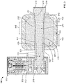
- FIG. 2 depicts an illustrative cross-sectional view of the hitch pin lock system, according to one or more embodiments described.
- FIG. 3 depicts another illustrative cross-sectional view of the hitch pin lock system, according to one or more embodiments described.
- FIG. 4 depicts an isometric view of a connector within a hitch basket, according to one or more embodiments described.
- first and second features are formed in direct contact
- additional features may be formed interposing the first and second features, such that the first and second features may not be in direct contact.
- exemplary embodiments presented below may be combined in any combination of ways, i.e., any element from one exemplary embodiment may be used in any other exemplary embodiment, without departing from the scope of the disclosure.
- up and “down”; “upward” and “downward”; “upper” and “lower”; “upwardly” and “downwardly”; “above” and “below”; and other like terms as used herein refer to relative positions to one another and are not intended to denote a particular spatial orientation since the apparatus and methods of using the same may be equally effective at various angles or orientations.
- FIG. 1 depicts an expanded view of an illustrative hitch pin lock 100 , according to one or more embodiments.
- the hitch pin lock 100 can include a lock rod 200 , and a locking member 300 .
- the hitch pin lock 100 is generally designed to secure an object to a vehicle.
- the hitch pin lock 100 of the present invention is designed to reduce movement and wobbling of the hitch pin lock 100 when a vehicle is in motion.
- the lock rod 200 , locking member 300 , connector 400 , and hitch basket 600 can be fabricated from any number of materials.
- suitable materials can include, but are not limited to, any one or more metals (such as aluminum, steel, stainless steel, brass, nickel), wood, other composite materials (such as ceramics, wood/polymer blends, cloth/polymer blends, etc.), and plastics (such as polyethylene, polypropylene, polystyrene, polyurethane, polyethylethylketone (PEEK), polytetrafluoroethylene (FTFE), polyamide resins (such as nylon 6 (N6), nylon 66 (N66)), polyester resins (such as polybutylene terephthalate (PBT), polyethylene terephthalate (PET), polyethylene is phthalate (PEI), PET/PEI copolymer) polynitrile resins (such as polyacrylonitrile (PAN), polymethacrylonitrile, acrylonitrile-styrene cop
- FIG. 2 depicts an illustrative cross-sectional view of the lock system 100 .
- the lock rod 200 can be composed of multiple sections each having different diameters to allow the lock rod 200 to more securely fit into the locking member collar or channel 310 .
- the lock rod 200 can have a first section 210 that has a threaded section 212 and an unthreaded section 214 .
- the threaded section 212 can be less than 60%, 50%, 40%, 30%, 20%, 10% of the total first section 210 .
- the threaded section 212 can be at least 0.25 in, at least 0.27 in, at least 0.35 in, at least 0.5 in, or at least 1 in long.
- the threaded section 212 can be between 0 in and 2 in, between 0.27 in and 2 in, between 0.27 in and 1.5 in, between 0.27 in and 1 in, or between 0.5 and 1 in long.
- the lock rod 200 can have a bolt head 216 .
- the bolt head 216 can consist of any type of bolt head size and shape known in the art (e.g., hex head, carriage bolt head, truss head, fillister head, etc.).
- a washer 218 can also be used with the lock rod 200 . Any type of appropriate washers can be used such as flat, square, locking, dock, fender, etc. Additionally, there can be a smooth section 219 that runs from the bottom of the bolt head 216 to the threaded section 212 .
- the smooth section 219 can be at least 0.25 in, at least, 0.5, at least 1 in long.
- the smooth section 219 can be between 0 in and 2 in, between 0 in and 1 in, between 0.25 in and 1.75 in, between 0.25 in and 1.5 in, between 0.25 in and 1 in. between 0.25 and 0.5 in long.
- the first section 210 of the lock rod 200 can be at least 0.25 in, at least 0.27 in, at least 0.35 in, at least 0.5 in, at least 1 in, or at least 1.5 in long.
- the first section 210 can be between 0 in and 4 in, between 0.27 in and 4 in, between 0.27 in and 3 in, between 0.27 in and 2 in, between 0.27 in and 1.5 in, between 0.27 in and 1 in.
- the second section 220 of the lock rod 200 can be at least 0.25 in, at least 0.27 in, at least 0.35 in, at least 0.5 in, at least 1 in, or at least 1.5 in long.
- the second section 220 can be between 0 in and 4 in, between 0.27 in and 4 in, between 0.27 in and 3 in, between 0.27 in and 2 in, between 0.27 in and 1.5 in, between 0.27 in and 1 in. Further, the second section 220 can be similar in length to the first section 210 .
- the length of the second section 220 can be between 90%-110% of the length of the first section 210 , between 80%-120% of the length of the first section 210 , between 70%-130% of the first section 210 , greater than 80% of the length of the first section 210 , greater than 90% of the length of the first section 210 , greater than 100% of the length of the first section 210 .
- the second section 220 can have a diameter that is smaller than the diameter of the first section 210 .
- the second section 220 can be designed to slide into channel 310 where it can be securely attached to locking member 300 .
- At least a portion of the inside diameter of channel 310 can be smaller than the outside diameter of the second section 220 of the lock rod 200 to prevent the lock rod 200 from penetrating too far into the channel 310 .
- the inside diameter of channel 310 can also be larger than the outside diameter of the first section 210 of the lock rod 200 .
- the top of channel 310 can include a tapered portion 314 that is adapted to receive a tapered portion 222 located on the outer diameter of the lock rod 200 between the first section 210 and the second section 220 . It is believed that this tapered portion 222 may help decrease the amount the lock system 100 wobbles when the system is attached to a moving vehicle.
- the lock rod 200 can have a have a tapered end 224 to receive locking member 300 .
- the lock rod 200 can further have a lock groove 226 to assist in securing the lock rod 200 to the locking member 300 .
- the locking member 300 can have one or more channels 310 , 312 .
- the second section 220 of the lock rod 200 can be entirely disposed within the locking member channel 310 .
- Channels 310 , 312 can be cylindrical, rectangular cuboid, triangular prism, square cuboid or any other shape. There can be 1, 2, or more channels 310 , 312 .
- Channel 310 can have a height outside the locking member 300 that is at least 0.5 in, at least 0.75 in, at least 1 in, at least 1.5 in or at least 2 in.
- Channel 310 can have a height outside the locking member 300 that is between 0 in and 3 in, between 0 in and 2.5 in, between 1 in and 3 in, between 1 in and 2.5 in or between 1.025 in and 2.275 in.
- Channel 312 can contain a lock 320 .
- Lock 320 can move between a locked position and an opened or unlocked position, wherein the second section 220 of the lock rod 200 is secured to the locking member 300 when the second section 220 is disposed within the channel 310 and the lock 320 is in the locked position, and the lock rod 200 is removable from the locking member 300 when the lock 320 is in the opened or unlocked position.
- a lock 320 of a known type can be used and which has an engaging member 330 , which secures the tapered end 224 of the lock rod 200 by use of a key or other locking mechanism.
- the engaging member 330 secures the tapered end 224 and the lock groove 226 of the lock rod 200 when in the locked position.
- the lock rod 200 is removable from the locking member 300 .
- a connector 400 can be inserted into a vehicle hitch 500 .
- connector 400 can also be attached to a hitch basket 600 .
- the connector 400 and hitch basket 600 can be made from a solid bar.
- the connector 400 and hitch basket 600 can be made from an aluminum solid bar.
- the connector 400 can have a channel 410 passing entirely through the connector 400 , defining a first end opening 420 and a second end opening 430 .
- the first end opening 420 and the second end opening 430 can be aligned with a first opening 510 and a second opening 520 formed through the vehicle hitch 500 .
- Channel 410 can have an internal threaded section 440 .
- the internal threaded section 440 is not a nut welded to the connector.
- the internal threaded section 440 can be at least 0.25 in, at least 0.27 in, at least 0.35 in, at least 0.5 in, or at least 1 in long.
- the internal threaded section 440 can be between 0 in and 2 in, between 0.27 in and 2 in, between 0.27 in and 1.5 in, between 0.27 in and 1 in, or between 0.5 and 1 in long.
- Channel 410 can also have a first unthreaded section 450 between the first end 420 and the internal threaded section 440 .
- the first unthreaded section 450 can be at least 0.25 in, at least 0.35 in, at least 0.5 in, or at least 1 in long.
- the first unthreaded section 450 can be between 0 in and 1.73 in, between 0.25 in and 1.73 in, between 0.25 in and 1.5 in, between 0.25 in and 1 in, or between 0.5 and 1 in long.
- Channel 410 can also have a second unthreaded section 460 between the second end 430 and the internal threaded section 440 .
- the second unthreaded section 460 can be at least 0.25 in, at least 0.35 in, at least 0.5 in, or at least 1 in long.
- the second unthreaded section 460 can be between 0 in and 1.73 in, between 0.25 in and 1.73 in, between 0.25 in and 1.5 in, between 0.25 in and 1 in, or between 0.5 and 1 in long.
- Lock rod 200 can pass through channel 410 and can secure the connector 400 to the hitch 500 .
- the threaded section 212 of the lock rod 200 can be attached to the internal threaded section 440 wherein the threads in the inside the channel 410 can match with and threadedly engage threaded section 212 of the lock rod 200 .
- the threaded section 212 of the lock rod 200 can be longer, shorter, or the same length as the internal threaded section 440 .
- the vehicle hitch 500 also can have internal threads (not shown) that match with and threadedly engage the threaded section 212 of the lock rod 200 .
- Vehicle hitch 500 would typically have a two (2) inch opening that receives connector 400 ; however, the present invention would work on vehicle hitches having larger or smaller openings. All of the threads described in this application can be right-handed or left-handed threads.
- the locking member channel 310 can be at least partially inserted into the connector channel 410 and the hitch 500 through the openings 430 and 520 .
- the distance from the channel 410 to the wall of the vehicle hitch opening 520 can be less than 0.0625 in, less than 0.05 in, less than 0.03125 in, less than 0.025 in, or less than 0.0156 in.
- the distance from the channel 410 to the wall of the vehicle hitch opening 520 can be between 0.005 in and 0.0625 in, between 0.005 in and 0.5 in, between 0.005 in and 0.03125 in, between 0.005 in and 0.025 in, or between 0.005 in and 0.0156 in.
- the distance from the channel 410 to the wall of the connector channel opening 430 can be less than 0.0625 in, less than 0.05 in, less than 0.03125 in, less than 0.025 in, or less than 0.0156 in.
- the distance from the channel 410 to the wall of the connector channel opening 430 can be between 0.005 in and 0.0625 in, between 0.005 in and 0.05 in, between 0.005 in and 0.03125 in, between 0.005 in and 0.025 in, or between 0.005 in and 0.0156 in.
- the distance from the channel 410 to the wall of the second unthreaded section 460 can be less than 0.0625 in, less than 0.05 in, less than 0.03125 in, less than 0.025 in, or less than 0.0156 in.
- the distance from the channel 410 to the wall of the second unthreaded section 460 can be between 0.005 in and 0.0625 in, between 0.005 in and 0.05 in, between 0.005 in and 0.03125 in, between 0.005 in and 0.025 in, or between 0.005 in and 0.0156 in.
- the distance from the end of the locking member channel 411 to the end of the vehicle hitch opening 521 can be at least 0.1 in, at least 0.2 in, at least 0.3 in, at least 0.4 in, at least 0.5 in, at least 0.6 in, at least 0.7 in, at least 0.8 in, at least 0.9 in, at least 1.0 in, at least 1.5 in.
- the distance from the end of the locking member channel 411 to the end of the vehicle hitch opening 521 can be between 0.1 in and 1 in, 0.2 in and 1 in, 0.3 in and 1 in, 0.4 in and 1 in, 0.5 in and 1 in, between 0.1 in and 1.5 in, 0.25 in and 1.5 in, 0.5 in and 1.5 in, 0.75 in and 1.5 in, 1.0 and 1.5 in, between 0.2 in and 2 in, 0.5 in and 2 in, 0.75 in and 2 in, 1.0 in and 2 in, 1.5 and 2 in.
Abstract
Description
Claims (20)
Priority Applications (1)
| Application Number | Priority Date | Filing Date | Title |
|---|---|---|---|
| US15/809,154 US10780751B2 (en) | 2017-11-10 | 2017-11-10 | Hitch pin lock systems |
Applications Claiming Priority (1)
| Application Number | Priority Date | Filing Date | Title |
|---|---|---|---|
| US15/809,154 US10780751B2 (en) | 2017-11-10 | 2017-11-10 | Hitch pin lock systems |
Publications (2)
| Publication Number | Publication Date |
|---|---|
| US20190143770A1 US20190143770A1 (en) | 2019-05-16 |
| US10780751B2 true US10780751B2 (en) | 2020-09-22 |
Family
ID=66431843
Family Applications (1)
| Application Number | Title | Priority Date | Filing Date |
|---|---|---|---|
| US15/809,154 Active 2038-03-24 US10780751B2 (en) | 2017-11-10 | 2017-11-10 | Hitch pin lock systems |
Country Status (1)
| Country | Link |
|---|---|
| US (1) | US10780751B2 (en) |
Cited By (4)
| Publication number | Priority date | Publication date | Assignee | Title |
|---|---|---|---|---|
| US11370256B2 (en) * | 2020-03-12 | 2022-06-28 | Gen-Y Creations, Llc | Hitch tightener |
| USD997044S1 (en) * | 2022-04-06 | 2023-08-29 | Bulletproof Hitches, LLC | Hitch pin |
| USD1011969S1 (en) * | 2023-08-25 | 2024-01-23 | Ting Luo | Tow hook |
| USD1016681S1 (en) * | 2017-01-27 | 2024-03-05 | Truck Shields, Llc | Hitch pin device |
Families Citing this family (1)
| Publication number | Priority date | Publication date | Assignee | Title |
|---|---|---|---|---|
| US11590814B2 (en) * | 2020-01-09 | 2023-02-28 | Ryan B. Schreier | Safety connector for trailers |
Citations (17)
| Publication number | Priority date | Publication date | Assignee | Title |
|---|---|---|---|---|
| US4473914A (en) * | 1982-09-30 | 1984-10-02 | Huck Manufacturing Company | Method and apparatus for manufacturing a stop and lock shoulder for a blind fastener sleeve |
| US20020073746A1 (en) * | 2000-04-24 | 2002-06-20 | Wyers Philip W. | Locking Device With Convertible Shank |
| US20020108407A1 (en) * | 2001-02-12 | 2002-08-15 | Zapushek John B. | Pin locking device and method of locking |
| US20020145270A1 (en) * | 2000-09-25 | 2002-10-10 | Marty Williams | Securing device for receiver hitches |
| US6609725B1 (en) * | 2000-09-25 | 2003-08-26 | Let's Go Aero, Inc. | Securing device for receiver hitch assemblies |
| US6773200B2 (en) * | 2001-01-31 | 2004-08-10 | Watermark Paddlesports, Inc. | Hitch-mountable recreational equipment rack |
| US20060017260A1 (en) * | 2002-11-27 | 2006-01-26 | Andersen John I | Systems and methods for providing an aluminum bar for towing |
| US7004491B1 (en) | 2003-04-22 | 2006-02-28 | Allsop, Inc. | Wedge tightening devices for hitch assemblies |
| US7066483B2 (en) * | 2003-05-28 | 2006-06-27 | Master Lock Company | Integral locking coupler |
| US20070180871A1 (en) * | 2006-02-08 | 2007-08-09 | Chris Irgens | Storage lock |
| US7338065B1 (en) * | 2003-05-20 | 2008-03-04 | Allsop, Inc. | Hitch assembly |
| US20080252042A1 (en) * | 2004-01-21 | 2008-10-16 | Sparkes Vernon W | Pivoting Hitch Assembly |
| US20110036129A1 (en) * | 2009-08-12 | 2011-02-17 | Frantz Donald R | Receiver lock assembly |
| US8302435B2 (en) * | 2008-08-25 | 2012-11-06 | Master Lock Company Llc | Pin locking device |
| US9242521B2 (en) * | 2012-01-25 | 2016-01-26 | John R. Columbia | Multi-function hitch accessory retaining device and method |
| US9616722B2 (en) * | 2012-11-06 | 2017-04-11 | Marty Williams | Securing device for receiver hitches |
| US20180117979A1 (en) * | 2016-11-02 | 2018-05-03 | John R. Columbia | Magnetic Fastening and Retaining Device and Method |
-
2017
- 2017-11-10 US US15/809,154 patent/US10780751B2/en active Active
Patent Citations (17)
| Publication number | Priority date | Publication date | Assignee | Title |
|---|---|---|---|---|
| US4473914A (en) * | 1982-09-30 | 1984-10-02 | Huck Manufacturing Company | Method and apparatus for manufacturing a stop and lock shoulder for a blind fastener sleeve |
| US20020073746A1 (en) * | 2000-04-24 | 2002-06-20 | Wyers Philip W. | Locking Device With Convertible Shank |
| US20020145270A1 (en) * | 2000-09-25 | 2002-10-10 | Marty Williams | Securing device for receiver hitches |
| US6609725B1 (en) * | 2000-09-25 | 2003-08-26 | Let's Go Aero, Inc. | Securing device for receiver hitch assemblies |
| US6773200B2 (en) * | 2001-01-31 | 2004-08-10 | Watermark Paddlesports, Inc. | Hitch-mountable recreational equipment rack |
| US20020108407A1 (en) * | 2001-02-12 | 2002-08-15 | Zapushek John B. | Pin locking device and method of locking |
| US20060017260A1 (en) * | 2002-11-27 | 2006-01-26 | Andersen John I | Systems and methods for providing an aluminum bar for towing |
| US7004491B1 (en) | 2003-04-22 | 2006-02-28 | Allsop, Inc. | Wedge tightening devices for hitch assemblies |
| US7338065B1 (en) * | 2003-05-20 | 2008-03-04 | Allsop, Inc. | Hitch assembly |
| US7066483B2 (en) * | 2003-05-28 | 2006-06-27 | Master Lock Company | Integral locking coupler |
| US20080252042A1 (en) * | 2004-01-21 | 2008-10-16 | Sparkes Vernon W | Pivoting Hitch Assembly |
| US20070180871A1 (en) * | 2006-02-08 | 2007-08-09 | Chris Irgens | Storage lock |
| US8302435B2 (en) * | 2008-08-25 | 2012-11-06 | Master Lock Company Llc | Pin locking device |
| US20110036129A1 (en) * | 2009-08-12 | 2011-02-17 | Frantz Donald R | Receiver lock assembly |
| US9242521B2 (en) * | 2012-01-25 | 2016-01-26 | John R. Columbia | Multi-function hitch accessory retaining device and method |
| US9616722B2 (en) * | 2012-11-06 | 2017-04-11 | Marty Williams | Securing device for receiver hitches |
| US20180117979A1 (en) * | 2016-11-02 | 2018-05-03 | John R. Columbia | Magnetic Fastening and Retaining Device and Method |
Non-Patent Citations (1)
| Title |
|---|
| Softride Bike Racks Catalog, 10 pages, downloaded from the internet at https://images.carid.com/softride/items/pdf/softride-product-catalog.pdf on Apr. 16, 2020. |
Cited By (4)
| Publication number | Priority date | Publication date | Assignee | Title |
|---|---|---|---|---|
| USD1016681S1 (en) * | 2017-01-27 | 2024-03-05 | Truck Shields, Llc | Hitch pin device |
| US11370256B2 (en) * | 2020-03-12 | 2022-06-28 | Gen-Y Creations, Llc | Hitch tightener |
| USD997044S1 (en) * | 2022-04-06 | 2023-08-29 | Bulletproof Hitches, LLC | Hitch pin |
| USD1011969S1 (en) * | 2023-08-25 | 2024-01-23 | Ting Luo | Tow hook |
Also Published As
| Publication number | Publication date |
|---|---|
| US20190143770A1 (en) | 2019-05-16 |
Similar Documents
| Publication | Publication Date | Title |
|---|---|---|
| US10780751B2 (en) | Hitch pin lock systems | |
| US7448820B1 (en) | Internal connector assembly for tubular members | |
| US8556288B1 (en) | Lockbox for a coupler of a trailer | |
| US7165426B2 (en) | Locking device with convertible shank including locking method thereof | |
| US7225649B2 (en) | Locking device having flange seal | |
| US20140138596A1 (en) | Cable railing | |
| US20060208458A1 (en) | Coupler lock | |
| US10197078B2 (en) | Robust adjustable panel insert | |
| US10384589B2 (en) | Container-securing device | |
| US8020885B2 (en) | Coupler lockout device | |
| EP1980444B1 (en) | Fixing device for additional mats in a motor vehicle | |
| DE20017376U1 (en) | Device for connecting a carrier, in particular a body part of a motor vehicle, to a plate element, in particular a door or wall covering | |
| US20200047679A1 (en) | Hitch coupling assembly for coupling an accessory to a vehicle | |
| KR101825176B1 (en) | Connecting apparatus for scaffold frame | |
| US20020067974A1 (en) | Push-in fastener assembly | |
| US20030115726A1 (en) | Clip having a solid locking structure | |
| US6726515B1 (en) | Stern lock-outboard lock | |
| US5257518A (en) | Locking device for locking a steering wheel of a car | |
| US20200386007A1 (en) | Security mounting bracket device for a crossbar | |
| US20020012577A1 (en) | Stern drive and outboard locks | |
| US9919642B2 (en) | Container-securing device | |
| US20090178247A1 (en) | Clip assembly | |
| US20220297611A1 (en) | Vehicle roof load bar mounting system | |
| US9611880B1 (en) | Connector usable with floating docks | |
| US5909990A (en) | Threadless nut |
Legal Events
| Date | Code | Title | Description |
|---|---|---|---|
| FEPP | Fee payment procedure |
Free format text: ENTITY STATUS SET TO UNDISCOUNTED (ORIGINAL EVENT CODE: BIG.); ENTITY STATUS OF PATENT OWNER: SMALL ENTITY |
|
| FEPP | Fee payment procedure |
Free format text: ENTITY STATUS SET TO SMALL (ORIGINAL EVENT CODE: SMAL); ENTITY STATUS OF PATENT OWNER: SMALL ENTITY |
|
| STPP | Information on status: patent application and granting procedure in general |
Free format text: DOCKETED NEW CASE - READY FOR EXAMINATION |
|
| AS | Assignment |
Owner name: PAKMULE, LLC, TEXAS Free format text: ASSIGNMENT OF ASSIGNORS INTEREST;ASSIGNOR:SARTIN, KANSAS RYAN;REEL/FRAME:046361/0275 Effective date: 20180713 |
|
| STPP | Information on status: patent application and granting procedure in general |
Free format text: NON FINAL ACTION MAILED |
|
| STPP | Information on status: patent application and granting procedure in general |
Free format text: RESPONSE TO NON-FINAL OFFICE ACTION ENTERED AND FORWARDED TO EXAMINER |
|
| STPP | Information on status: patent application and granting procedure in general |
Free format text: FINAL REJECTION MAILED |
|
| STPP | Information on status: patent application and granting procedure in general |
Free format text: RESPONSE AFTER FINAL ACTION FORWARDED TO EXAMINER |
|
| STPP | Information on status: patent application and granting procedure in general |
Free format text: NOTICE OF ALLOWANCE MAILED -- APPLICATION RECEIVED IN OFFICE OF PUBLICATIONS |
|
| STPP | Information on status: patent application and granting procedure in general |
Free format text: AWAITING TC RESP, ISSUE FEE PAYMENT VERIFIED |
|
| STPP | Information on status: patent application and granting procedure in general |
Free format text: PUBLICATIONS -- ISSUE FEE PAYMENT VERIFIED |
|
| STCF | Information on status: patent grant |
Free format text: PATENTED CASE |
|
| MAFP | Maintenance fee payment |
Free format text: PAYMENT OF MAINTENANCE FEE, 4TH YR, SMALL ENTITY (ORIGINAL EVENT CODE: M2551); ENTITY STATUS OF PATENT OWNER: SMALL ENTITY Year of fee payment: 4 |