US10779606B2 - System and method for controlling active recovery based on detected parameter - Google Patents
System and method for controlling active recovery based on detected parameter Download PDFInfo
- Publication number
- US10779606B2 US10779606B2 US16/399,572 US201916399572A US10779606B2 US 10779606 B2 US10779606 B2 US 10779606B2 US 201916399572 A US201916399572 A US 201916399572A US 10779606 B2 US10779606 B2 US 10779606B2
- Authority
- US
- United States
- Prior art keywords
- controller
- operable
- physiological parameter
- control signal
- signal
- Prior art date
- Legal status (The legal status is an assumption and is not a legal conclusion. Google has not performed a legal analysis and makes no representation as to the accuracy of the status listed.)
- Active
Links
- 238000000034 method Methods 0.000 title claims description 13
- 238000011084 recovery Methods 0.000 title description 34
- 230000007246 mechanism Effects 0.000 claims abstract description 116
- 238000004891 communication Methods 0.000 claims abstract description 17
- 230000036772 blood pressure Effects 0.000 claims description 27
- 230000008859 change Effects 0.000 claims description 22
- 239000008280 blood Substances 0.000 description 10
- 210000004369 blood Anatomy 0.000 description 10
- 230000017531 blood circulation Effects 0.000 description 6
- 230000008569 process Effects 0.000 description 6
- 230000004044 response Effects 0.000 description 4
- 239000002699 waste material Substances 0.000 description 3
- 230000009471 action Effects 0.000 description 2
- 238000012986 modification Methods 0.000 description 2
- 230000004048 modification Effects 0.000 description 2
- 238000012544 monitoring process Methods 0.000 description 2
- 238000005086 pumping Methods 0.000 description 2
- 230000000386 athletic effect Effects 0.000 description 1
- 244000309466 calf Species 0.000 description 1
- 230000001413 cellular effect Effects 0.000 description 1
- 230000001351 cycling effect Effects 0.000 description 1
- 230000035487 diastolic blood pressure Effects 0.000 description 1
- 230000000694 effects Effects 0.000 description 1
- 230000006870 function Effects 0.000 description 1
- 210000004072 lung Anatomy 0.000 description 1
- 238000012806 monitoring device Methods 0.000 description 1
- 235000015097 nutrients Nutrition 0.000 description 1
- 230000003287 optical effect Effects 0.000 description 1
- 230000029058 respiratory gaseous exchange Effects 0.000 description 1
- 230000000284 resting effect Effects 0.000 description 1
- 230000035488 systolic blood pressure Effects 0.000 description 1
Images


Classifications
-
- A—HUMAN NECESSITIES
- A61—MEDICAL OR VETERINARY SCIENCE; HYGIENE
- A61B—DIAGNOSIS; SURGERY; IDENTIFICATION
- A61B5/00—Measuring for diagnostic purposes; Identification of persons
- A61B5/02—Detecting, measuring or recording pulse, heart rate, blood pressure or blood flow; Combined pulse/heart-rate/blood pressure determination; Evaluating a cardiovascular condition not otherwise provided for, e.g. using combinations of techniques provided for in this group with electrocardiography or electroauscultation; Heart catheters for measuring blood pressure
- A61B5/021—Measuring pressure in heart or blood vessels
-
- A43B3/0005—
-
- A—HUMAN NECESSITIES
- A43—FOOTWEAR
- A43B—CHARACTERISTIC FEATURES OF FOOTWEAR; PARTS OF FOOTWEAR
- A43B1/00—Footwear characterised by the material
- A43B1/0054—Footwear characterised by the material provided with magnets, magnetic parts or magnetic substances
-
- A—HUMAN NECESSITIES
- A43—FOOTWEAR
- A43B—CHARACTERISTIC FEATURES OF FOOTWEAR; PARTS OF FOOTWEAR
- A43B13/00—Soles; Sole-and-heel integral units
- A43B13/14—Soles; Sole-and-heel integral units characterised by the constructive form
- A43B13/18—Resilient soles
- A43B13/20—Pneumatic soles filled with a compressible fluid, e.g. air, gas
-
- A—HUMAN NECESSITIES
- A43—FOOTWEAR
- A43B—CHARACTERISTIC FEATURES OF FOOTWEAR; PARTS OF FOOTWEAR
- A43B3/00—Footwear characterised by the shape or the use
- A43B3/34—Footwear characterised by the shape or the use with electrical or electronic arrangements
-
- A—HUMAN NECESSITIES
- A61—MEDICAL OR VETERINARY SCIENCE; HYGIENE
- A61B—DIAGNOSIS; SURGERY; IDENTIFICATION
- A61B5/00—Measuring for diagnostic purposes; Identification of persons
- A61B5/0002—Remote monitoring of patients using telemetry, e.g. transmission of vital signals via a communication network
- A61B5/0015—Remote monitoring of patients using telemetry, e.g. transmission of vital signals via a communication network characterised by features of the telemetry system
- A61B5/0024—Remote monitoring of patients using telemetry, e.g. transmission of vital signals via a communication network characterised by features of the telemetry system for multiple sensor units attached to the patient, e.g. using a body or personal area network
-
- A—HUMAN NECESSITIES
- A61—MEDICAL OR VETERINARY SCIENCE; HYGIENE
- A61B—DIAGNOSIS; SURGERY; IDENTIFICATION
- A61B5/00—Measuring for diagnostic purposes; Identification of persons
- A61B5/68—Arrangements of detecting, measuring or recording means, e.g. sensors, in relation to patient
- A61B5/6801—Arrangements of detecting, measuring or recording means, e.g. sensors, in relation to patient specially adapted to be attached to or worn on the body surface
- A61B5/6802—Sensor mounted on worn items
- A61B5/6804—Garments; Clothes
- A61B5/6807—Footwear
-
- G—PHYSICS
- G05—CONTROLLING; REGULATING
- G05B—CONTROL OR REGULATING SYSTEMS IN GENERAL; FUNCTIONAL ELEMENTS OF SUCH SYSTEMS; MONITORING OR TESTING ARRANGEMENTS FOR SUCH SYSTEMS OR ELEMENTS
- G05B15/00—Systems controlled by a computer
- G05B15/02—Systems controlled by a computer electric
-
- A—HUMAN NECESSITIES
- A43—FOOTWEAR
- A43B—CHARACTERISTIC FEATURES OF FOOTWEAR; PARTS OF FOOTWEAR
- A43B13/00—Soles; Sole-and-heel integral units
- A43B13/14—Soles; Sole-and-heel integral units characterised by the constructive form
- A43B13/18—Resilient soles
- A43B13/20—Pneumatic soles filled with a compressible fluid, e.g. air, gas
- A43B13/203—Pneumatic soles filled with a compressible fluid, e.g. air, gas provided with a pump or valve
-
- A—HUMAN NECESSITIES
- A61—MEDICAL OR VETERINARY SCIENCE; HYGIENE
- A61B—DIAGNOSIS; SURGERY; IDENTIFICATION
- A61B5/00—Measuring for diagnostic purposes; Identification of persons
- A61B5/01—Measuring temperature of body parts ; Diagnostic temperature sensing, e.g. for malignant or inflamed tissue
-
- A—HUMAN NECESSITIES
- A61—MEDICAL OR VETERINARY SCIENCE; HYGIENE
- A61B—DIAGNOSIS; SURGERY; IDENTIFICATION
- A61B5/00—Measuring for diagnostic purposes; Identification of persons
- A61B5/02—Detecting, measuring or recording pulse, heart rate, blood pressure or blood flow; Combined pulse/heart-rate/blood pressure determination; Evaluating a cardiovascular condition not otherwise provided for, e.g. using combinations of techniques provided for in this group with electrocardiography or electroauscultation; Heart catheters for measuring blood pressure
- A61B5/0205—Simultaneously evaluating both cardiovascular conditions and different types of body conditions, e.g. heart and respiratory condition
- A61B5/02055—Simultaneously evaluating both cardiovascular condition and temperature
-
- A—HUMAN NECESSITIES
- A61—MEDICAL OR VETERINARY SCIENCE; HYGIENE
- A61B—DIAGNOSIS; SURGERY; IDENTIFICATION
- A61B5/00—Measuring for diagnostic purposes; Identification of persons
- A61B5/02—Detecting, measuring or recording pulse, heart rate, blood pressure or blood flow; Combined pulse/heart-rate/blood pressure determination; Evaluating a cardiovascular condition not otherwise provided for, e.g. using combinations of techniques provided for in this group with electrocardiography or electroauscultation; Heart catheters for measuring blood pressure
- A61B5/024—Detecting, measuring or recording pulse rate or heart rate
-
- A—HUMAN NECESSITIES
- A61—MEDICAL OR VETERINARY SCIENCE; HYGIENE
- A61B—DIAGNOSIS; SURGERY; IDENTIFICATION
- A61B5/00—Measuring for diagnostic purposes; Identification of persons
- A61B5/08—Detecting, measuring or recording devices for evaluating the respiratory organs
- A61B5/0816—Measuring devices for examining respiratory frequency
Definitions
- the present invention generally relates to devices and methods to improve blood flow and recovery.
- FIGS. 1A-B illustrate the plantar venous plexus, wherein FIG. 1A illustrates a bottom view of a foot and FIG. 1B illustrates a side view of the foot;
- FIG. 2 illustrates a shoe in accordance with aspects of the present invention
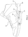
- FIG. 3 illustrates another shoe in accordance with other aspects of the present invention
- FIGS. 4A-B illustrate a force actuating mechanism in retracted and extended states in accordance with aspects of the present invention
- FIG. 5 illustrates a force actuating mechanism in retracted and extended states over time in accordance with aspects of the present invention.
- FIG. 6 illustrates a process by which active recovery is achieved in response to a detected parameter in accordance with aspects of the present invention.
- a shoe for use by a user and for use with a communication device that is operable to transmit a physiological parameter signal (e.g., a blood pressure signal) based on a detected physiological parameter (e.g., a detected blood pressure) of the user.
- the shoe includes a sole, a force actuating mechanism, a receiver and a controller.
- the sole has a top surface for supporting the foot of the user when being worn by the user.
- the force actuating mechanism provides a force normal to the top surface of the sole.
- the force actuating mechanism is disposed at the sole so as to provide the force to a plantar venous plexus of the foot.
- the receiver receives the physiological parameter signal.
- the controller generates a control signal to control the force actuating mechanism.
- the controller is further operable to modify the control signal based on the received physiological parameter signal.
- FIGS. 1A-B illustrate the plantar venous plexus, wherein FIG. 1A illustrates a bottom view of a foot and FIG. 1B illustrates a side view of the foot.
- a plantar venous plexus 104 is generally located in the central portion of the plantar side of a foot 102 .
- Plantar venous plexus 104 is an area of foot 102 that functions to pump blood back up the leg from the foot and is also known as the venous foot pump.
- plantar venous plexus 104 is directly involved with the action of walking, with the pressures exerted on the foot during the walking cycle serving to effectively pump the blood.
- the purpose is to pump deoxygenated blood up the leg to the next stage pump, called the calf pump.
- the pumping action serves to take blood that has delivered nutrients to the foot and move the blood back toward the heart and lungs, taking all the waste products with it.
- FIG. 2 illustrates a shoe in accordance with aspects of the present invention.
- a system 200 includes a shoe 202 and a communication device 218 .
- Shoe 202 further includes a force actuating mechanism 206 , a receiver 208 , a controller 210 and a sole 204 .
- Sole 204 further includes a top surface 212 .
- Communication device 218 can be any device that can detect a parameter and transmit signals based on the detected parameter including, but not limited to, an activity monitoring device, a smartwatch, a cellular telephone and a tablet computer. Transmitting data may be accomplished via wireless means including, but not limited to, Bluetooth and WiFi.
- Communication device 218 detects a parameter and wirelessly transmits signals based on the parameter to receiver 208 .
- the detected parameter can be any number of physiological parameters including, but not limited to, blood pressure, heart rate, temperature, moisture, salinity and breathing rate.
- Receiver 208 receives signals from communication device 218 and sends those signals to controller 210 via line 214 .
- Controller 210 receives communications from receiver 208 via line 214 , and provides instructions to force actuating mechanism 206 via line 216 .
- the instructions provided to force actuating mechanism 206 are based on the communications from receiver 208 .
- Force actuating mechanism 206 receives instructions from controller 210 via line 216 and executes those instructions received from controller 210 , resulting in force actuating mechanism 206 extending or retracting. Force actuating mechanism 206 is in contact with top surface 212 . As force actuating mechanism 206 extends, it exerts a force on plantar venous plexus 104 and as it retracts, it releases the force exerted on plantar venous plexus 104 .
- Force actuating mechanism 206 can be any type of known actuator that can extend or retract, including, but not limited to, hydraulic, pneumatic, electric, thermal, magnetic or mechanical.
- force actuating mechanism 206 , receiver 208 and controller 210 are shown as separate elements. However, in some embodiments, at least two of force actuating mechanism 206 , receiver 208 and controller 210 may be combined as a unitary device.
- At least one of force actuating mechanism 206 , receiver 208 and controller 210 may be implemented as a computer having tangible computer-readable media for carrying or having computer-executable instructions or data structures stored thereon.
- Such tangible computer-readable media can be any available media that can be accessed by a general purpose or special purpose computer.
- Non-limiting examples of tangible computer-readable media include physical storage and/or memory media such as RAM, ROM, EEPROM, CD-ROM or other optical disk storage, magnetic disk storage or other magnetic storage devices, or any other medium which can be used to carry or store desired program code means in the form of computer-executable instructions or data structures and which can be accessed by a general purpose or special purpose computer.
- any such connection may be properly termed a computer-readable medium. Combinations of the above should also be included within the scope of computer-readable media.
- system 200 will be further described with reference to FIG. 6 .
- FIG. 3 illustrates another shoe in accordance with other aspects of the present invention
- a shoe 302 includes a detector 308 .
- Detector 308 detects a parameter, generates a signal based on the parameter and provides the signal to controller 210 via line 214 .
- At least one of force actuating mechanism 206 , detector 308 and controller 210 may be implemented as a computer having tangible computer-readable media for carrying or having computer-executable instructions or data structures stored thereon.
- Such tangible computer-readable media can be any available media that can be accessed by a general purpose or special purpose computer.
- shoe 302 will be further described with reference to FIG. 6 .
- FIGS. 4A-B illustrate a force actuating mechanism in retracted and extended states in accordance with aspects of the present invention.
- force actuating mechanism 206 includes a surface 402 and an extending mechanism 404 .
- Surface 402 is in contact with both extending mechanism 404 and top surface 212 .
- force actuating mechanism 206 is in a retracted state with the height of extending mechanism 404 denoted by height h min .
- surface 402 is not pushing against sole 212 and sole 212 is not pushing against the foot of the wearer.
- plantar venous plexus 104 is not compressed, meaning that force actuating mechanism 206 is not acting to pump blood through plantar venous plexus 104 .
- force actuating mechanism 206 is in an extended state with the height of extending mechanism 404 denoted by height h max .
- surface 402 is pushing against sole 212 and sole 212 is pushing against the bottom of the foot of the wearer.
- extending mechanism 404 pushing against the foot of the wearer, plantar venous plexus 104 is compressed, meaning that force actuating mechanism 206 is acting to pump blood through plantar venous plexus 104 .
- force actuating mechanism 206 moving from a retracted to an extended state will be further described with reference to FIGS. 5-6 .
- FIG. 5 illustrates a force actuating mechanism in retracted and extended states over time in accordance with aspects of the present invention.
- extending mechanism 404 is at height h min , indicating that extending mechanism 404 is in the fully retracted state.
- t 2 extending mechanism 404 has moved to height h 1 , pushing surface 402 into sole 212 and as sole 212 is forced upwards, it pushes against plantar venous plexus 104 , aiding blood flow.
- t 3 extending mechanism 404 is once again at height h min , the fully retracted state, wherein plantar venous plexus 104 is not acting to aid blood flow.
- extending mechanism 404 is at height h max , indicating that extending mechanism 404 is in the fully extended state. In the fully extended state, sole 212 is forced against plantar venous plexus 104 to the maximum allowable amount, aiding blood flow during active recovery.
- t 5 extending mechanism 404 is at height h 2 , forcing sole 212 against plantar venous plexus 104 , aiding blood flow.
- FIG. 6 illustrates a process by which active recovery is achieved in response to a detected parameter in accordance with aspects of the present invention.
- process 600 starts (S 602 ), and a parameter is detected (S 604 ).
- the user has finished a strenuous exercise and desires to engage in active recovery.
- the user puts on shoe 202 to begin active recovery.
- the active recovery is based on a parameter detected by communication device 218 , which the user is wearing.
- communication device 218 is detecting the user's blood pressure.
- time when the user puts on shoe 202 corresponds with time t 1 where extending mechanism 404 is fully retracted.
- communication device 218 detects the user's blood pressure.
- the user may put on shoe 302 to engage in active recovery.
- detector 308 detects the user's blood pressure.
- the parameter control signal is generated and transmitted (S 606 ).
- communication device 218 After communication device 218 detects the user's blood pressure, communication device 218 generates a parameter control signal based on the user's blood pressure. Communication device 218 then wirelessly transmits the parameter control signal to receiver 208 . Receiver 208 then transmits the parameter control signal to controller 210 via line 214 .
- detector 308 After detector 308 detects user's blood pressure, detector 308 generates a parameter control signal based on the user's blood pressure. Detector 308 then transmits the parameter control signal to controller 210 via line 214 .
- the mechanism control signal is generated (S 608 ).
- controller 210 receives the parameter control signal from either receiver 208 or detector 308 . Controller 210 then uses the data contained in the parameter control signal to generate a mechanism control signal that is based on the user's blood pressure.
- controller 210 has a memory therein (not shown) that is operable to store blood pressure relationship data to be used for determining active foot recovery parameters.
- controller 210 may have any known data structure, a non-limiting example of which includes a look up table, wherein a blood pressure is associated with a predetermined prescribed active foot recovery.
- Non-limiting examples of predetermined prescribed active foot recovery include total time of active recovery as applied by force actuating mechanism 206 , duty cycle of force actuating mechanism 206 during active foot recovery, maximum height of force actuating mechanism 206 during active foot recovery, minimum height of force actuating mechanism 206 during active foot recovery, frequency of force actuating mechanism 206 during active foot recovery and combinations thereof.
- controller 210 may include data associating a systolic blood pressure of 121 mm Hg and a diastolic blood pressure of 83 mm Hg to require active foot recovery to be performed such that force actuating mechanism 206 has a 50/50 duty cycle, with a minimum height of 0 mm, a maximum height of 15 mm and a frequency of 30 Hz for a time period of 20 minutes.
- Controller 310 uses the blood pressure information within the parameter control signal and the corresponding relationship data stored therein to generate the mechanism control signal.
- the mechanism control signal will instruct force actuating mechanism 206 how to operate during active recovery.
- Controller 210 transmits the mechanism control signal to force actuating mechanism 206 via line 216 .
- active recovery is performed (S 610 ).
- force actuating mechanism 206 receives the mechanism control signal from controller 210 via line 216 and begins active recovery.
- the mechanism control signal instructs force actuating mechanism 206 to lower extending mechanism 404 from height h 1 at time t 2 to height h min at time t 3 .
- Force actuating mechanism 206 then cycles the states shown at times t 1 -t 3 , to aid in active foot recovery in response to the user's blood pressure p 1 .
- controller 310 uses the blood pressure information within the parameter control signal and the corresponding relationship data stored therein to generate the mechanism control signal.
- the mechanism control signal will instruct force actuating mechanism 206 how to operate during active recovery.
- Controller 210 transmits the mechanism control signal to force actuating mechanism 206 via line 216 .
- the mechanism control signal instructs force actuating mechanism 206 to raise extending mechanism 404 from height h min at time t 3 to height h max at time t 4 .
- force actuating mechanism 206 then cycles the states shown at times t 3 and t 4 , for example passing through the state shown at time t 5 to aid in active foot recovery in response to the user's blood pressure p 2 .
- process 600 ends (S 614 ).
- controller 210 may modify the pulse width, pulse number or pulse amplitude of the mechanism control signal it sends to force actuating mechanism 206 .
- Controller 210 may change the time intervals directly by modifying the mechanism control signal it sends to force actuating mechanism 206 . Controller 210 may also change the time intervals indirectly by modifying the pulse width, pulse number or pulse amplitude of the mechanism control signal it sends to force actuating mechanism 206 .
- Controller 210 may also change the speed at which force actuating mechanism 206 extends or retracts, which will also alter the time intervals. Further, controller 210 may modify how long force actuating mechanism 206 remains in a given position, thus altering the overall time intervals between cycles.
Abstract
Description
Claims (17)
Priority Applications (1)
| Application Number | Priority Date | Filing Date | Title |
|---|---|---|---|
| US16/399,572 US10779606B2 (en) | 2016-07-19 | 2019-04-30 | System and method for controlling active recovery based on detected parameter |
Applications Claiming Priority (2)
| Application Number | Priority Date | Filing Date | Title |
|---|---|---|---|
| US15/213,749 US10327499B1 (en) | 2016-07-19 | 2016-07-19 | System and method for controlling active recovery based on detected parameter |
| US16/399,572 US10779606B2 (en) | 2016-07-19 | 2019-04-30 | System and method for controlling active recovery based on detected parameter |
Related Parent Applications (1)
| Application Number | Title | Priority Date | Filing Date |
|---|---|---|---|
| US15/213,749 Continuation US10327499B1 (en) | 2016-07-19 | 2016-07-19 | System and method for controlling active recovery based on detected parameter |
Publications (2)
| Publication Number | Publication Date |
|---|---|
| US20190254379A1 US20190254379A1 (en) | 2019-08-22 |
| US10779606B2 true US10779606B2 (en) | 2020-09-22 |
Family
ID=66996478
Family Applications (2)
| Application Number | Title | Priority Date | Filing Date |
|---|---|---|---|
| US15/213,749 Active 2037-07-14 US10327499B1 (en) | 2016-07-19 | 2016-07-19 | System and method for controlling active recovery based on detected parameter |
| US16/399,572 Active US10779606B2 (en) | 2016-07-19 | 2019-04-30 | System and method for controlling active recovery based on detected parameter |
Family Applications Before (1)
| Application Number | Title | Priority Date | Filing Date |
|---|---|---|---|
| US15/213,749 Active 2037-07-14 US10327499B1 (en) | 2016-07-19 | 2016-07-19 | System and method for controlling active recovery based on detected parameter |
Country Status (1)
| Country | Link |
|---|---|
| US (2) | US10327499B1 (en) |
Families Citing this family (1)
| Publication number | Priority date | Publication date | Assignee | Title |
|---|---|---|---|---|
| US10327499B1 (en) * | 2016-07-19 | 2019-06-25 | Under Armour, Inc. | System and method for controlling active recovery based on detected parameter |
Citations (4)
| Publication number | Priority date | Publication date | Assignee | Title |
|---|---|---|---|---|
| US20170273849A1 (en) | 2016-03-28 | 2017-09-28 | Under Armour, Inc. | Active recorery system and method having capacitive proximity sensor |
| US20170273615A1 (en) | 2016-03-28 | 2017-09-28 | Under Armour, Inc. | System and method for monitoring efficiency verses fatigue |
| US10102722B2 (en) * | 2015-12-18 | 2018-10-16 | Immersion Corporation | Wearable article having an actuator that performs non-haptic and haptic operations |
| US10327499B1 (en) * | 2016-07-19 | 2019-06-25 | Under Armour, Inc. | System and method for controlling active recovery based on detected parameter |
-
2016
- 2016-07-19 US US15/213,749 patent/US10327499B1/en active Active
-
2019
- 2019-04-30 US US16/399,572 patent/US10779606B2/en active Active
Patent Citations (4)
| Publication number | Priority date | Publication date | Assignee | Title |
|---|---|---|---|---|
| US10102722B2 (en) * | 2015-12-18 | 2018-10-16 | Immersion Corporation | Wearable article having an actuator that performs non-haptic and haptic operations |
| US20170273849A1 (en) | 2016-03-28 | 2017-09-28 | Under Armour, Inc. | Active recorery system and method having capacitive proximity sensor |
| US20170273615A1 (en) | 2016-03-28 | 2017-09-28 | Under Armour, Inc. | System and method for monitoring efficiency verses fatigue |
| US10327499B1 (en) * | 2016-07-19 | 2019-06-25 | Under Armour, Inc. | System and method for controlling active recovery based on detected parameter |
Also Published As
| Publication number | Publication date |
|---|---|
| US20190254379A1 (en) | 2019-08-22 |
| US10327499B1 (en) | 2019-06-25 |
Similar Documents
| Publication | Publication Date | Title |
|---|---|---|
| US20210244604A1 (en) | Treatment devices and methods | |
| US11511089B2 (en) | Systems and methods for treating pulmonary hypertension | |
| US10179082B2 (en) | Compressive therapeutic device | |
| KR101304177B1 (en) | Compression garment apparatus having support bladder | |
| JP2018523534A5 (en) | ||
| US20170273849A1 (en) | Active recorery system and method having capacitive proximity sensor | |
| WO2016073777A1 (en) | Telemedical wearable sensing system for management of chronic venous disorders | |
| US20150157087A1 (en) | Adjustable shoe | |
| US10779606B2 (en) | System and method for controlling active recovery based on detected parameter | |
| CN105963908B (en) | The method and intelligent wearable device of treadmill are controlled by intelligent wearable device | |
| JP2015528335A (en) | Method for determining body part dimensions as part of a pressure therapy procedure | |
| CA3019907C (en) | System and method for synchronizing external compression of a limb for increased blood flow | |
| US20170164899A1 (en) | Devices embedded smart shoes | |
| JP2012071136A5 (en) | ||
| GB2527282A (en) | Support device | |
| US20160037939A1 (en) | Active multicompartmental pressure redistribution system | |
| JP2012501196A5 (en) | ||
| US20200093383A1 (en) | Apparatus and methods of sensing a patient condition, such as anatomy position, and of controlling patient applications | |
| US20200121201A1 (en) | Method and device for the time-resolved measurement of characteristic variables of the cardiac function | |
| JP2018532438A (en) | Chest compression according to chest compliance | |
| US9125655B2 (en) | Correction and optimization of wave reflection in blood vessels | |
| KR101968407B1 (en) | Ankle stimulation device and method using low frequency stimulation foot orthosis device | |
| KR102064591B1 (en) | Smart shoes system for calculating energy expenditure | |
| JP2018198886A (en) | Footwear and system | |
| US20240148334A1 (en) | Estimation apparatus, estimation method, and non-transitory computer-readable recording medium |
Legal Events
| Date | Code | Title | Description |
|---|---|---|---|
| AS | Assignment |
Owner name: UNDER ARMOUR, INC., MARYLAND Free format text: ASSIGNMENT OF ASSIGNORS INTEREST;ASSIGNORS:OLESON, MARK A;KOVACH, F GRANT;DAU, NATHAN;AND OTHERS;SIGNING DATES FROM 20160606 TO 20160630;REEL/FRAME:049039/0583 |
|
| FEPP | Fee payment procedure |
Free format text: ENTITY STATUS SET TO UNDISCOUNTED (ORIGINAL EVENT CODE: BIG.); ENTITY STATUS OF PATENT OWNER: LARGE ENTITY |
|
| STPP | Information on status: patent application and granting procedure in general |
Free format text: DOCKETED NEW CASE - READY FOR EXAMINATION |
|
| STPP | Information on status: patent application and granting procedure in general |
Free format text: NON FINAL ACTION MAILED |
|
| AS | Assignment |
Owner name: JPMORGAN CHASE BANK, N.A., AS ADMINISTRATIVE AGENT, ILLINOIS Free format text: SECURITY INTEREST;ASSIGNOR:UNDER ARMOUR, INC.;REEL/FRAME:052654/0756 Effective date: 20200512 |
|
| STPP | Information on status: patent application and granting procedure in general |
Free format text: NOTICE OF ALLOWANCE MAILED -- APPLICATION RECEIVED IN OFFICE OF PUBLICATIONS |
|
| STPP | Information on status: patent application and granting procedure in general |
Free format text: PUBLICATIONS -- ISSUE FEE PAYMENT VERIFIED |
|
| STCF | Information on status: patent grant |
Free format text: PATENTED CASE |
|
| MAFP | Maintenance fee payment |
Free format text: PAYMENT OF MAINTENANCE FEE, 4TH YEAR, LARGE ENTITY (ORIGINAL EVENT CODE: M1551); ENTITY STATUS OF PATENT OWNER: LARGE ENTITY Year of fee payment: 4 |