US10778135B2 - Motor parallel winding differential current protection - Google Patents
Motor parallel winding differential current protection Download PDFInfo
- Publication number
- US10778135B2 US10778135B2 US16/176,882 US201816176882A US10778135B2 US 10778135 B2 US10778135 B2 US 10778135B2 US 201816176882 A US201816176882 A US 201816176882A US 10778135 B2 US10778135 B2 US 10778135B2
- Authority
- US
- United States
- Prior art keywords
- winding
- current
- phase
- differential
- differential current
- Prior art date
- Legal status (The legal status is an assumption and is not a legal conclusion. Google has not performed a legal analysis and makes no representation as to the accuracy of the status listed.)
- Active
Links
- 238000004804 winding Methods 0.000 title claims abstract description 250
- 230000003862 health status Effects 0.000 claims abstract description 14
- 238000000034 method Methods 0.000 claims description 29
- 230000003247 decreasing effect Effects 0.000 claims description 6
- 230000004044 response Effects 0.000 claims description 6
- 230000001010 compromised effect Effects 0.000 claims description 3
- 238000004891 communication Methods 0.000 description 12
- 238000012544 monitoring process Methods 0.000 description 5
- 230000036541 health Effects 0.000 description 4
- 238000005259 measurement Methods 0.000 description 4
- 230000015556 catabolic process Effects 0.000 description 3
- 238000006731 degradation reaction Methods 0.000 description 3
- 230000000670 limiting effect Effects 0.000 description 3
- 230000008569 process Effects 0.000 description 2
- 230000002829 reductive effect Effects 0.000 description 2
- 230000008859 change Effects 0.000 description 1
- 238000007796 conventional method Methods 0.000 description 1
- 230000001419 dependent effect Effects 0.000 description 1
- 238000010586 diagram Methods 0.000 description 1
- 230000000694 effects Effects 0.000 description 1
- 238000012986 modification Methods 0.000 description 1
- 230000004048 modification Effects 0.000 description 1
- 230000036961 partial effect Effects 0.000 description 1
- 230000010287 polarization Effects 0.000 description 1
Images


Classifications
-
- H—ELECTRICITY
- H02—GENERATION; CONVERSION OR DISTRIBUTION OF ELECTRIC POWER
- H02P—CONTROL OR REGULATION OF ELECTRIC MOTORS, ELECTRIC GENERATORS OR DYNAMO-ELECTRIC CONVERTERS; CONTROLLING TRANSFORMERS, REACTORS OR CHOKE COILS
- H02P25/00—Arrangements or methods for the control of AC motors characterised by the kind of AC motor or by structural details
- H02P25/16—Arrangements or methods for the control of AC motors characterised by the kind of AC motor or by structural details characterised by the circuit arrangement or by the kind of wiring
- H02P25/22—Multiple windings; Windings for more than three phases
-
- H—ELECTRICITY
- H02—GENERATION; CONVERSION OR DISTRIBUTION OF ELECTRIC POWER
- H02H—EMERGENCY PROTECTIVE CIRCUIT ARRANGEMENTS
- H02H7/00—Emergency protective circuit arrangements specially adapted for specific types of electric machines or apparatus or for sectionalised protection of cable or line systems, and effecting automatic switching in the event of an undesired change from normal working conditions
- H02H7/08—Emergency protective circuit arrangements specially adapted for specific types of electric machines or apparatus or for sectionalised protection of cable or line systems, and effecting automatic switching in the event of an undesired change from normal working conditions for dynamo-electric motors
- H02H7/0833—Emergency protective circuit arrangements specially adapted for specific types of electric machines or apparatus or for sectionalised protection of cable or line systems, and effecting automatic switching in the event of an undesired change from normal working conditions for dynamo-electric motors for electric motors with control arrangements
- H02H7/0844—Fail safe control, e.g. by comparing control signal and controlled current, isolating motor on commutation error
-
- H—ELECTRICITY
- H02—GENERATION; CONVERSION OR DISTRIBUTION OF ELECTRIC POWER
- H02P—CONTROL OR REGULATION OF ELECTRIC MOTORS, ELECTRIC GENERATORS OR DYNAMO-ELECTRIC CONVERTERS; CONTROLLING TRANSFORMERS, REACTORS OR CHOKE COILS
- H02P29/00—Arrangements for regulating or controlling electric motors, appropriate for both AC and DC motors
- H02P29/02—Providing protection against overload without automatic interruption of supply
- H02P29/024—Detecting a fault condition, e.g. short circuit, locked rotor, open circuit or loss of load
- H02P29/0243—Detecting a fault condition, e.g. short circuit, locked rotor, open circuit or loss of load the fault being a broken phase
-
- H—ELECTRICITY
- H02—GENERATION; CONVERSION OR DISTRIBUTION OF ELECTRIC POWER
- H02P—CONTROL OR REGULATION OF ELECTRIC MOTORS, ELECTRIC GENERATORS OR DYNAMO-ELECTRIC CONVERTERS; CONTROLLING TRANSFORMERS, REACTORS OR CHOKE COILS
- H02P29/00—Arrangements for regulating or controlling electric motors, appropriate for both AC and DC motors
- H02P29/02—Providing protection against overload without automatic interruption of supply
- H02P29/024—Detecting a fault condition, e.g. short circuit, locked rotor, open circuit or loss of load
- H02P29/027—Detecting a fault condition, e.g. short circuit, locked rotor, open circuit or loss of load the fault being an over-current
-
- H—ELECTRICITY
- H02—GENERATION; CONVERSION OR DISTRIBUTION OF ELECTRIC POWER
- H02P—CONTROL OR REGULATION OF ELECTRIC MOTORS, ELECTRIC GENERATORS OR DYNAMO-ELECTRIC CONVERTERS; CONTROLLING TRANSFORMERS, REACTORS OR CHOKE COILS
- H02P29/00—Arrangements for regulating or controlling electric motors, appropriate for both AC and DC motors
- H02P29/02—Providing protection against overload without automatic interruption of supply
- H02P29/024—Detecting a fault condition, e.g. short circuit, locked rotor, open circuit or loss of load
- H02P29/028—Detecting a fault condition, e.g. short circuit, locked rotor, open circuit or loss of load the motor continuing operation despite the fault condition, e.g. eliminating, compensating for or remedying the fault
-
- B—PERFORMING OPERATIONS; TRANSPORTING
- B64—AIRCRAFT; AVIATION; COSMONAUTICS
- B64D—EQUIPMENT FOR FITTING IN OR TO AIRCRAFT; FLIGHT SUITS; PARACHUTES; ARRANGEMENT OR MOUNTING OF POWER PLANTS OR PROPULSION TRANSMISSIONS IN AIRCRAFT
- B64D2221/00—Electric power distribution systems onboard aircraft
-
- H—ELECTRICITY
- H02—GENERATION; CONVERSION OR DISTRIBUTION OF ELECTRIC POWER
- H02P—CONTROL OR REGULATION OF ELECTRIC MOTORS, ELECTRIC GENERATORS OR DYNAMO-ELECTRIC CONVERTERS; CONTROLLING TRANSFORMERS, REACTORS OR CHOKE COILS
- H02P2205/00—Indexing scheme relating to controlling arrangements characterised by the control loops
- H02P2205/01—Current loop, i.e. comparison of the motor current with a current reference
Definitions
- Electric motors are commonly used to convert electrical power into mechanical power to operate various devices on an aircraft.
- ‘more electric’ aircraft architectures increasingly employ growing numbers of alternating current (AC) electric motors to operate devices traditionally powered hydraulically. Using such electric motors can aid in reducing weight and simplifying the arrangement of the aircraft.
- AC electric motors typically employ three-phase windings, which are provided AC power by the aircraft electrical system, and may operate at high frequency in cooperation with a motor controller.
- the system also includes a motor controller connected to the electric motor, the motor controller operable to direct the combined phase current through the phase lead, receive the differential current signal, determine if the differential current flowing through the winding set exceeds a selected threshold, and identify a health status of the motor winding set as degraded or operate in a reduced performance mode “Limp mode” if the differential current exceeds the selected threshold.
- further embodiments may include that the electric motor is a multiphase electric machine and the phase lead corresponds to a first phase of a plurality of phases.
- further embodiments may include a second winding set corresponding to a second phase of the plurality of phases, the second winding set including third winding carrying a third current and a fourth windings carrying a fourth current connected to the second phase lead, the third winding connected in parallel with the fourth winding, the third current and the fourth current based on the second combined phase current.
- further embodiments may include a second differential current sensor operably coupled to the third winding and the fourth winding, the differential current sensor measuring a second differential current based on the third current flowing through the third winding and the fourth current flowing through the fourth winding and operable to transmit a signal indicative of the second differential current based on the measuring.
- further embodiments may include that the second winding set extends between the electric motor and the motor controller.
- further embodiments may include that the first winding set extends between the electric motor and the motor controller.
- further embodiments may include a current sensor operably connected to the phase lead, the current sensor operable to measure the combined phase current.
- further embodiments may include that the first selected threshold is based on a percentage of the combined phase current.
- further embodiments may include the controller decreasing current flow through at least one of the first winding and the second winding in response to identifying the health status of the electric machine as degraded or compromised.
- the electric motor includes an electric motor having a phase lead operable to carry a combined phase current and a first winding set including first and second windings connected to the phase lead, the second winding connected in parallel with the first winding, and where the first and second windings operable to carry a first current and a second current respectively, based on the combined phase current.
- the electric motor also includes a differential current sensor operably coupled to the first winding and the second winding, the differential current sensor measuring a differential current based on the first current and the second current flowing through the first winding and the second winding and operable to transmit a signal indicative of the differential current based on the measuring.
- further embodiments of the electric motor may include that the electric motor is a multiphase electric machine and the phase lead corresponds to a first phase of a plurality of phases.
- further embodiments of the electric motor may include a second phase lead corresponding to a second phase of the plurality of phases, the second phase lead operable to carry a second combined phase current.
- further embodiments of the electric motor may include a second winding set corresponding to a second phase of the plurality of phases, the second winding set including third winding carrying a third current and a fourth windings carrying a fourth current connected to the second phase lead, the third winding connected in parallel with the fourth winding, the third current and the fourth current based on the second combined phase current.
- Also described herein in yet another embodiment is a method operating an electric machine having a parallel winding set.
- the method includes controlling, by a motor controller, a combined current and directing a first current through a first winding and a second current through a second winding of the parallel winding set, the first current and the second current based on the combined current and sensing a differential current flow between the first current in the first winding and the second current in the second winding of the parallel winding set.
- the method also includes determining if the differential current exceeds a first selected threshold and identifying the health status of the electric machine as degraded or failed if the differential current exceeds the first selected threshold.
- further embodiments may include that the electric motor is a multiphase electric machine and the phase lead corresponds to a first phase of a plurality of phases.
- further embodiments of the method may include controlling, by the motor controller, a second combined current and directing a third current through a third winding and a fourth current through a fourth winding of a second parallel winding set, the third current and the fourth current based on the second combined current, and sensing a second differential current flow between third current in the third winding and the fourth current in the fourth winding of the second parallel winding set.
- the further embodiments may also include determining if the second differential current exceeds a second selected threshold and identifying the health status of the electric machine as degraded or failed if the second differential current exceeds the second selected threshold.
- further embodiments may include that the second selected threshold is based on selected threshold is based at least in part on the combined phase current, a total current supplied to the motor, a thermal capability of the motor, a loss exhibited as a result of an imbalance between the third winding and the fourth winding.
- further embodiments may include that the first selected threshold is based on a percentage of the combined phase current.
- further embodiments may include that the first selected threshold is based on selected threshold is based at least in part on the combined phase current, a total current supplied to the motor, a thermal capability of the motor, a loss exhibited as a result of an imbalance between the first winding and the second winding.
- Embodiments of the present disclosure include a motor control system with a motor having paralleled windings that include current sensors that measure differential currents within parallel phase windings of the motor attached thereto.
- a technical effect of such embodiments is that the differential current sensors can identify any difference in currents to the parallel windings for each phase of the winding and thereby identify a potential degradation of the motor windings or a fault condition.
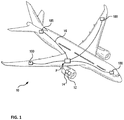
- FIG. 1 is a diagram, showing an aircraft power distribution system in communication with an electric machine
- FIG. 2 is a schematic view of an embodiment of the electric machine of FIG. 1 , showing current sensors coupled to winding sets of the electric machine within a motor controller;
- FIG. 4 process flow chart of a method of sensing current flow in an electric machine, showing steps of the method in accordance with an embodiment.
- FIG. 1 For purposes of explanation and illustration, and not limitation, a partial view of an exemplary embodiment of an electric machine in accordance with the disclosure is shown in FIG. 1 and is designated generally by reference character 100 .
- FIGS. 2-4 Other embodiments of electric machine and methods of monitoring current flow within winding sets in accordance with the disclosure, or aspects thereof, are provided in FIGS. 2-4 , as will be described.
- the systems and methods described herein can be used sensing current flow through parallel winding sets in electric machine in aircraft, though the present disclosure is not limited to aircraft applications.
- Aircraft 10 includes an engine 12 , a generator electric machine 14 , a power distribution system 16 , and one or more motors 100 , e.g., a motor electric machine.
- the engine 12 is operably connected to the generator electric machine 14 .
- the generator electric machine 14 is arranged to generate electrical power (P) using mechanical power received from the engine 12 .
- the power is provided to the power distribution system 16 , which connects the generator electric machine 14 to the motor 100 and provides the electrical power P thereto.
- a current sensing arrangement for motor 100 is described herein in the following exemplary embodiments, it is to be understood and appreciated the described current sensing arrangement can also be applied to a generator electric machine, e.g., generator electric machine 14 .
- the motor 100 includes parallel windings that extend out of the motor 100 and into the motor controller 118 , wherein they couple to a single phase lead e.g., 102 .
- This allows for placement of differential current sensors e.g., 110 , directly on the parallel winding leads, where they can directly measure differential current flow through the parallel windings e.g., 106 , 108 instead of relying on inferential measurements obtained from the combined current sensor 116 on phase lead 102 or individual current sensors associated with each parallel winding.
- the A-phase first current sensor 110 and the A-phase combined current sensor 116 are communicative with the motor controller 118 , the A-phase differential current sensor 110 being coupled to the A-phase first winding 106 and A-phase second winding 108 to provide an A-phase differential current signal 112 (See FIG. 3 ) to the motor controller 118 and an A-phase combined current sensor 116 being coupled to the A-phase lead 102 to provide an A-phase combined current signal 170 ( FIG. 3 ) to the motor controller 118 .
- the motor controller 118 can reduce the power applied to A-phase winding set 104 when the differential current flow between A-phase first winding 106 and A-phase second winding 108 is outside of predetermined range, or level.
- the winding set can extend from the motor 100 into motor controller 118 such that each current sensor (e.g., 110 , 116 ) can be housed within the motor controller 118 , with each of the six windings (e.g., 106 , 108 , 136 , 138 , 148 , and 150 ) entering motor controller 118 for current measurement and connection to phase leads 102 , 124 , and 126 , which terminate within motor controller 118 .
- each current sensor e.g., 110 , 116
- each of the six windings e.g., 106 , 108 , 136 , 138 , 148 , and 150
- the B-phase winding set 128 includes a B-phase first winding 136 , a B-phase second winding 138 , a B-phase differential current sensor 140 .
- the B-phase second winding 138 is connected in parallel with the B-phase first winding 136 .
- the B-phase differential current sensor 140 is differentially coupled to the B-phase first winding 136 and the B-phase second winding 138 and is communicative with the motor controller 118 for providing a B-phase differential current signal 172 indicative of the differential between the current 142 flowing in the B-phase first winding 136 and the current 146 flowing through the B-phase second winding 138 .
- the B-phase combined current sensor 144 is coupled to the B-phase lead 124 and is communicative with the motor controller 118 for providing a signal indicative of the total current flowing through the B-phase lead 124 to/from the motor controller 118 .
- the motor controller 118 includes a housing 160 , processor 162 , an interface 164 , a memory 166 , and a communications link 168 .
- Each of the parallel phase windings e.g., A-phase first winding 106 , A-phase second winding 108 , B-phase first winding 136 , B-phase second winding 138 , C-phase first winding 148 , and C-phase second winding 150 , extend from the motor 100 (shown in FIG. 1 ) and into an interior of housing 160 , where they electrically connect with respective the phase leads, e.g., A-phase lead 102 (shown in FIG. 2 ), B-phase lead 124 (shown in FIG. 2 ), and C-phase lead 126 (shown in FIG. 2 ).
- the differential current sensors 110 , 140 , and 152 inductively couple to each of the of the parallel windings sets (e.g., 104 , 128 , and 138 ) within the interior of housing 160 for providing signals indicative of the differential current flow through the respective winding sets 104 , 128 , and 130 .
- the A-phase differential current sensor 110 inductively couples to the A-phase first winding 106 to and to the A-phase second winding 108
- the B-phase differential current sensor 140 inductively couples to the B-phase first winding 136 and to the B-phase second winding 138 .
- the combined current sensors 116 , 144 , and 154 inductively couple to each of the phase legs within the interior of housing 160 for providing signals indicative of the combined current flow through each respective phase lead 102 , 124 , and 126 .
- the A-phase combined current sensor 116 inductively couples to the A-phase lead 102
- the B-phase combined current sensor 144 inductively couples to the B-phase lead 124
- the C-phase combined current sensor 154 inductively couples to the C-phase lead 126 .
- the B-phase differential current sensor 140 reports differential current flow through the B-phase first winding 136 and the B-phase second winding 138 via a B-phase differential current signal 172 provided to communications link 168 .
- the B-phase combined current sensor 144 reports current flow through the B-phase lead 124 via the B-phase combined current signal 174 , which are also provided to communications link 168 .
- the C-phase differential current sensor 152 reports differential current flow through the C-phase first winding 148 and the C-phase second winding 150 via a C-phase differential current signal 176 provided to communications link 168
- the C-phase combined current sensor 154 reports current flow through the C-phase lead 126 via a C-phase combined current signal 178 , which are additionally provided to the communications link 168 .
- processor 162 when the comparison indicates that differential current between the parallel windings e.g., 106 , 108 of the winding set (e.g., 104 , 128 , 130 ) is within a selected threshold, processor 162 deems the phase set (e.g., 104 , 128 , 130 ) healthy. When the comparison indicates that differential current between the parallel windings of the winding set (e.g., 104 , 128 , 130 ) is not within the selected threshold processor 162 deems motor 100 unhealthy.
- a health status report, and or warning report 182 can be issued by processor 162 via a communications link 184 to an electrical system manager, aircraft control system, warning to the pilot and the like.
- Method 200 includes flowing current through first and second parallel windings, e.g., A-phase first winding 106 (shown in FIG. 2 ) and second phase second winding 108 (shown in FIG. 2 ), in a winding set (e.g., 104 , 128 , 130 ), as depicted with process step 210 .
- first and second parallel windings e.g., A-phase first winding 106 (shown in FIG. 2 ) and second phase second winding 108 (shown in FIG. 2 ), in a winding set (e.g., 104 , 128 , 130 ), as depicted with process step 210 .
- Differential current flow through the first winding e.g., 106 , 136 , and 148 and the second winding e.g., 108 , 138 , 150 is sensed using a differential current sensor(s) e.g., 110 , 140 , and 152 coupled to the first winding (e.g., 106 , 136 , and 148 ) and the second winding (e.g., 108 , 138 , 150 ), as shown at process step 220 .
- the method 200 continues at process step 230 with determining if the measured differential current exceeds a selected threshold.
- the motor controller 118 may continue operating the electric machine, e.g., motor 100 at a reduced power or remove the motor 100 from operation.
- the comparison indicates that the differential current for a given winding set (e.g., 104 , 128 , 130 ), is within the predetermined threshold, monitoring continues as the process reiterates.
Landscapes
- Engineering & Computer Science (AREA)
- Power Engineering (AREA)
- Control Of Ac Motors In General (AREA)
- Control Of Electric Motors In General (AREA)
- Tests Of Circuit Breakers, Generators, And Electric Motors (AREA)
Priority Applications (2)
| Application Number | Priority Date | Filing Date | Title |
|---|---|---|---|
| US16/176,882 US10778135B2 (en) | 2018-10-31 | 2018-10-31 | Motor parallel winding differential current protection |
| EP19206023.4A EP3648336B1 (fr) | 2018-10-31 | 2019-10-29 | Protection de courant différentiel d'enroulement parallèle de moteur et procedure associe |
Applications Claiming Priority (1)
| Application Number | Priority Date | Filing Date | Title |
|---|---|---|---|
| US16/176,882 US10778135B2 (en) | 2018-10-31 | 2018-10-31 | Motor parallel winding differential current protection |
Publications (2)
| Publication Number | Publication Date |
|---|---|
| US20200136550A1 US20200136550A1 (en) | 2020-04-30 |
| US10778135B2 true US10778135B2 (en) | 2020-09-15 |
Family
ID=68392817
Family Applications (1)
| Application Number | Title | Priority Date | Filing Date |
|---|---|---|---|
| US16/176,882 Active US10778135B2 (en) | 2018-10-31 | 2018-10-31 | Motor parallel winding differential current protection |
Country Status (2)
| Country | Link |
|---|---|
| US (1) | US10778135B2 (fr) |
| EP (1) | EP3648336B1 (fr) |
Cited By (1)
| Publication number | Priority date | Publication date | Assignee | Title |
|---|---|---|---|---|
| US11799354B2 (en) | 2021-09-22 | 2023-10-24 | GM Global Technology Operations LLC | Current imbalance fault mitigation for rotary electric machine with parallel stator windings |
Families Citing this family (1)
| Publication number | Priority date | Publication date | Assignee | Title |
|---|---|---|---|---|
| FR3128837A1 (fr) * | 2021-11-02 | 2023-05-05 | Alstom Transport Technologies | Système et procédé de calcul d’écart de couple entre au moins deux moteurs à induction asynchrones |
Citations (15)
| Publication number | Priority date | Publication date | Assignee | Title |
|---|---|---|---|---|
| US4953054A (en) | 1987-06-19 | 1990-08-28 | Gerhard Fetzer | Circuit for protection against fault currents |
| CA2071397A1 (fr) | 1991-09-05 | 1993-03-06 | John F. Kral | Dispositif de detection et de commutation des courants de defaut pour bloc d'alimentation en courant continu alimente en ca |
| US5705909A (en) | 1995-12-14 | 1998-01-06 | General Motors Corporation | Control for AC motor having parallel sets of three-phase windings with only one current sensor per set |
| US7233123B2 (en) | 2004-07-06 | 2007-06-19 | Cummins Generator Technologies Limited | Electrical machine rotor position identification |
| US7253634B1 (en) * | 2006-03-31 | 2007-08-07 | General Electric Company | Generator protection methods and systems self-tuning to a plurality of characteristics of a machine |
| US20080080106A1 (en) | 2006-09-29 | 2008-04-03 | Behrooz Mirafzal | Integrated DC link inductor and common mode current sensor winding |
| US7646160B2 (en) | 2007-04-26 | 2010-01-12 | Ford Global Technologies, Llc | Sensor calibration and parameter identification in a multi-phase motor drive |
| US20120229144A1 (en) | 2011-03-10 | 2012-09-13 | Hitachi, Ltd. | Electric rotating machine |
| US20140117912A1 (en) * | 2011-07-04 | 2014-05-01 | Zoran Gajic | System For Detecting Internal Winding Faults Of A Synchronous Generator, Computer Program Product And Method |
| US8810189B2 (en) * | 2011-02-25 | 2014-08-19 | Deere & Company | Machine systems including pre-power diagnostics |
| US9018881B2 (en) | 2013-01-10 | 2015-04-28 | GM Global Technology Operations LLC | Stator winding diagnostic systems and methods |
| US20160025811A1 (en) * | 2014-07-24 | 2016-01-28 | Schweitzer Engineering Laboratories, Inc. | Systems and methods for monitoring and protecting an electric power generator |
| US20160178699A1 (en) | 2013-08-02 | 2016-06-23 | Schaeffler Technologies AG & Co. KG | Method for determining a fault in an electronically commutated electric motor |
| WO2016178667A1 (fr) | 2015-05-05 | 2016-11-10 | Schlumberger Canada Limited | Gestion des défaillances dans des moteurs polyphasés |
| EP3370335A1 (fr) | 2017-03-03 | 2018-09-05 | Hamilton Sundstrand Corporation | Détection de courant dans des machines électriques |
-
2018
- 2018-10-31 US US16/176,882 patent/US10778135B2/en active Active
-
2019
- 2019-10-29 EP EP19206023.4A patent/EP3648336B1/fr active Active
Patent Citations (17)
| Publication number | Priority date | Publication date | Assignee | Title |
|---|---|---|---|---|
| US4953054A (en) | 1987-06-19 | 1990-08-28 | Gerhard Fetzer | Circuit for protection against fault currents |
| CA2071397A1 (fr) | 1991-09-05 | 1993-03-06 | John F. Kral | Dispositif de detection et de commutation des courants de defaut pour bloc d'alimentation en courant continu alimente en ca |
| US5705909A (en) | 1995-12-14 | 1998-01-06 | General Motors Corporation | Control for AC motor having parallel sets of three-phase windings with only one current sensor per set |
| US7233123B2 (en) | 2004-07-06 | 2007-06-19 | Cummins Generator Technologies Limited | Electrical machine rotor position identification |
| US7253634B1 (en) * | 2006-03-31 | 2007-08-07 | General Electric Company | Generator protection methods and systems self-tuning to a plurality of characteristics of a machine |
| US7528611B2 (en) | 2006-03-31 | 2009-05-05 | General Electric Company | Methods and system for detecting winding faults in a generator with parallel windings |
| US20080080106A1 (en) | 2006-09-29 | 2008-04-03 | Behrooz Mirafzal | Integrated DC link inductor and common mode current sensor winding |
| US7646160B2 (en) | 2007-04-26 | 2010-01-12 | Ford Global Technologies, Llc | Sensor calibration and parameter identification in a multi-phase motor drive |
| US8810189B2 (en) * | 2011-02-25 | 2014-08-19 | Deere & Company | Machine systems including pre-power diagnostics |
| US20120229144A1 (en) | 2011-03-10 | 2012-09-13 | Hitachi, Ltd. | Electric rotating machine |
| US20140117912A1 (en) * | 2011-07-04 | 2014-05-01 | Zoran Gajic | System For Detecting Internal Winding Faults Of A Synchronous Generator, Computer Program Product And Method |
| US9018881B2 (en) | 2013-01-10 | 2015-04-28 | GM Global Technology Operations LLC | Stator winding diagnostic systems and methods |
| US20160178699A1 (en) | 2013-08-02 | 2016-06-23 | Schaeffler Technologies AG & Co. KG | Method for determining a fault in an electronically commutated electric motor |
| US20160025811A1 (en) * | 2014-07-24 | 2016-01-28 | Schweitzer Engineering Laboratories, Inc. | Systems and methods for monitoring and protecting an electric power generator |
| WO2016178667A1 (fr) | 2015-05-05 | 2016-11-10 | Schlumberger Canada Limited | Gestion des défaillances dans des moteurs polyphasés |
| EP3370335A1 (fr) | 2017-03-03 | 2018-09-05 | Hamilton Sundstrand Corporation | Détection de courant dans des machines électriques |
| US20180254735A1 (en) | 2017-03-03 | 2018-09-06 | Hamilton Sundstrand Corporation | Current sensing in electric machines |
Non-Patent Citations (1)
| Title |
|---|
| Extended European Search Report for application No. 19206023.4-1202 dated Mar. 4, 2020, 9 pages. |
Cited By (1)
| Publication number | Priority date | Publication date | Assignee | Title |
|---|---|---|---|---|
| US11799354B2 (en) | 2021-09-22 | 2023-10-24 | GM Global Technology Operations LLC | Current imbalance fault mitigation for rotary electric machine with parallel stator windings |
Also Published As
| Publication number | Publication date |
|---|---|
| EP3648336B1 (fr) | 2022-05-04 |
| EP3648336A1 (fr) | 2020-05-06 |
| US20200136550A1 (en) | 2020-04-30 |
Similar Documents
| Publication | Publication Date | Title |
|---|---|---|
| US9810743B2 (en) | Deterioration diagnosis system | |
| JP5875734B2 (ja) | 電動機の診断装置および開閉装置 | |
| EP2730023B1 (fr) | Système, produit de programme informatique et procédé de détection des défauts d'enroulement internes d'un générateur synchrone | |
| EP3268760B1 (fr) | Dispositif de surveillance de terre neutre de générateur à l'aide d'une mesure et d'une analyse de composantes de courant continu | |
| EP2482411B1 (fr) | Protection contre la défaillance d'entraînement | |
| EP2908148B1 (fr) | Détection de défaillances de diode redresseuse dans des dispositifs d'excitation sans balais | |
| CN105143894B (zh) | 用于检测三相ac电路中的过度电压降的系统和方法 | |
| KR20170074986A (ko) | 전동기의 진단 장치 | |
| KR101228386B1 (ko) | 전동기 절연 상태 진단 시스템 | |
| EP3648336B1 (fr) | Protection de courant différentiel d'enroulement parallèle de moteur et procedure associe | |
| US11342875B2 (en) | Electric motors with neutral voltage sensing | |
| EP3370335B1 (fr) | Détection de courant dans des machines électriques | |
| Deeb et al. | Three-phase induction motor short circuits fault diagnosis using MCSA and NSC | |
| US9075099B2 (en) | Method for adaptation of ground fault detection | |
| US11163013B2 (en) | Electrical device partial discharge monitoring | |
| JP7217682B2 (ja) | 回転電機の診断システム及び診断方法 | |
| CN108151795B (zh) | 用于配置状态监测装置的方法及系统 | |
| JPH0554913B2 (fr) |
Legal Events
| Date | Code | Title | Description |
|---|---|---|---|
| AS | Assignment |
Owner name: HAMILTON SUNDSTRAND CORPORATION, NORTH CAROLINA Free format text: ASSIGNMENT OF ASSIGNORS INTEREST;ASSIGNORS:KOENIG, ANDREAS C.;COLDWATE, JOSEPH KENNETH;MENKE, MICHAEL J.;AND OTHERS;SIGNING DATES FROM 20181029 TO 20181031;REEL/FRAME:047373/0637 |
|
| FEPP | Fee payment procedure |
Free format text: ENTITY STATUS SET TO UNDISCOUNTED (ORIGINAL EVENT CODE: BIG.); ENTITY STATUS OF PATENT OWNER: LARGE ENTITY |
|
| STPP | Information on status: patent application and granting procedure in general |
Free format text: NOTICE OF ALLOWANCE MAILED -- APPLICATION RECEIVED IN OFFICE OF PUBLICATIONS |
|
| STPP | Information on status: patent application and granting procedure in general |
Free format text: PUBLICATIONS -- ISSUE FEE PAYMENT VERIFIED |
|
| STCF | Information on status: patent grant |
Free format text: PATENTED CASE |
|
| MAFP | Maintenance fee payment |
Free format text: PAYMENT OF MAINTENANCE FEE, 4TH YEAR, LARGE ENTITY (ORIGINAL EVENT CODE: M1551); ENTITY STATUS OF PATENT OWNER: LARGE ENTITY Year of fee payment: 4 |