US10776973B2 - Vanishing point computation for single vanishing point images - Google Patents
Vanishing point computation for single vanishing point images Download PDFInfo
- Publication number
- US10776973B2 US10776973B2 US15/972,779 US201815972779A US10776973B2 US 10776973 B2 US10776973 B2 US 10776973B2 US 201815972779 A US201815972779 A US 201815972779A US 10776973 B2 US10776973 B2 US 10776973B2
- Authority
- US
- United States
- Prior art keywords
- line segments
- image
- vanishing point
- background image
- planes
- Prior art date
- Legal status (The legal status is an assumption and is not a legal conclusion. Google has not performed a legal analysis and makes no representation as to the accuracy of the status listed.)
- Active, expires
Links
- 238000000034 method Methods 0.000 claims abstract description 65
- 238000004364 calculation method Methods 0.000 claims description 21
- 238000010200 validation analysis Methods 0.000 claims description 16
- 238000002790 cross-validation Methods 0.000 claims description 8
- 238000003064 k means clustering Methods 0.000 claims description 8
- 239000000203 mixture Substances 0.000 abstract 1
- 230000008569 process Effects 0.000 description 41
- 238000002156 mixing Methods 0.000 description 21
- 230000011218 segmentation Effects 0.000 description 12
- 230000000694 effects Effects 0.000 description 5
- 230000000740 bleeding effect Effects 0.000 description 3
- 230000007423 decrease Effects 0.000 description 3
- 230000015654 memory Effects 0.000 description 3
- 238000000465 moulding Methods 0.000 description 3
- 230000003287 optical effect Effects 0.000 description 3
- 230000009471 action Effects 0.000 description 2
- 230000003190 augmentative effect Effects 0.000 description 2
- 238000005192 partition Methods 0.000 description 2
- 230000008447 perception Effects 0.000 description 2
- 230000000007 visual effect Effects 0.000 description 2
- 238000007792 addition Methods 0.000 description 1
- 230000004075 alteration Effects 0.000 description 1
- 230000005540 biological transmission Effects 0.000 description 1
- 230000001143 conditioned effect Effects 0.000 description 1
- 230000007246 mechanism Effects 0.000 description 1
- 238000012986 modification Methods 0.000 description 1
- 230000004048 modification Effects 0.000 description 1
- 238000009877 rendering Methods 0.000 description 1
- 230000001953 sensory effect Effects 0.000 description 1
- 239000013589 supplement Substances 0.000 description 1
- XLYOFNOQVPJJNP-UHFFFAOYSA-N water Substances O XLYOFNOQVPJJNP-UHFFFAOYSA-N 0.000 description 1
Images


Classifications
-
- G06T3/02—
-
- G—PHYSICS
- G06—COMPUTING; CALCULATING OR COUNTING
- G06F—ELECTRIC DIGITAL DATA PROCESSING
- G06F18/00—Pattern recognition
- G06F18/20—Analysing
- G06F18/23—Clustering techniques
- G06F18/232—Non-hierarchical techniques
- G06F18/2321—Non-hierarchical techniques using statistics or function optimisation, e.g. modelling of probability density functions
- G06F18/23213—Non-hierarchical techniques using statistics or function optimisation, e.g. modelling of probability density functions with fixed number of clusters, e.g. K-means clustering
-
- G—PHYSICS
- G06—COMPUTING; CALCULATING OR COUNTING
- G06T—IMAGE DATA PROCESSING OR GENERATION, IN GENERAL
- G06T11/00—2D [Two Dimensional] image generation
- G06T11/60—Editing figures and text; Combining figures or text
-
- G—PHYSICS
- G06—COMPUTING; CALCULATING OR COUNTING
- G06T—IMAGE DATA PROCESSING OR GENERATION, IN GENERAL
- G06T3/00—Geometric image transformation in the plane of the image
- G06T3/0093—Geometric image transformation in the plane of the image for image warping, i.e. transforming by individually repositioning each pixel
-
- G06T3/18—
-
- G—PHYSICS
- G06—COMPUTING; CALCULATING OR COUNTING
- G06T—IMAGE DATA PROCESSING OR GENERATION, IN GENERAL
- G06T3/00—Geometric image transformation in the plane of the image
- G06T3/40—Scaling the whole image or part thereof
-
- G—PHYSICS
- G06—COMPUTING; CALCULATING OR COUNTING
- G06T—IMAGE DATA PROCESSING OR GENERATION, IN GENERAL
- G06T7/00—Image analysis
- G06T7/10—Segmentation; Edge detection
- G06T7/12—Edge-based segmentation
-
- G—PHYSICS
- G06—COMPUTING; CALCULATING OR COUNTING
- G06T—IMAGE DATA PROCESSING OR GENERATION, IN GENERAL
- G06T7/00—Image analysis
- G06T7/10—Segmentation; Edge detection
- G06T7/13—Edge detection
-
- G—PHYSICS
- G06—COMPUTING; CALCULATING OR COUNTING
- G06T—IMAGE DATA PROCESSING OR GENERATION, IN GENERAL
- G06T7/00—Image analysis
- G06T7/10—Segmentation; Edge detection
- G06T7/143—Segmentation; Edge detection involving probabilistic approaches, e.g. Markov random field [MRF] modelling
-
- G—PHYSICS
- G06—COMPUTING; CALCULATING OR COUNTING
- G06T—IMAGE DATA PROCESSING OR GENERATION, IN GENERAL
- G06T7/00—Image analysis
- G06T7/10—Segmentation; Edge detection
- G06T7/187—Segmentation; Edge detection involving region growing; involving region merging; involving connected component labelling
-
- G—PHYSICS
- G06—COMPUTING; CALCULATING OR COUNTING
- G06T—IMAGE DATA PROCESSING OR GENERATION, IN GENERAL
- G06T7/00—Image analysis
- G06T7/50—Depth or shape recovery
- G06T7/536—Depth or shape recovery from perspective effects, e.g. by using vanishing points
-
- G—PHYSICS
- G06—COMPUTING; CALCULATING OR COUNTING
- G06T—IMAGE DATA PROCESSING OR GENERATION, IN GENERAL
- G06T7/00—Image analysis
- G06T7/70—Determining position or orientation of objects or cameras
- G06T7/73—Determining position or orientation of objects or cameras using feature-based methods
-
- G—PHYSICS
- G06—COMPUTING; CALCULATING OR COUNTING
- G06V—IMAGE OR VIDEO RECOGNITION OR UNDERSTANDING
- G06V10/00—Arrangements for image or video recognition or understanding
- G06V10/70—Arrangements for image or video recognition or understanding using pattern recognition or machine learning
- G06V10/762—Arrangements for image or video recognition or understanding using pattern recognition or machine learning using clustering, e.g. of similar faces in social networks
- G06V10/763—Non-hierarchical techniques, e.g. based on statistics of modelling distributions
-
- G06K9/6223—
-
- G—PHYSICS
- G06—COMPUTING; CALCULATING OR COUNTING
- G06T—IMAGE DATA PROCESSING OR GENERATION, IN GENERAL
- G06T2207/00—Indexing scheme for image analysis or image enhancement
- G06T2207/10—Image acquisition modality
- G06T2207/10004—Still image; Photographic image
-
- G—PHYSICS
- G06—COMPUTING; CALCULATING OR COUNTING
- G06T—IMAGE DATA PROCESSING OR GENERATION, IN GENERAL
- G06T2207/00—Indexing scheme for image analysis or image enhancement
- G06T2207/20—Special algorithmic details
- G06T2207/20112—Image segmentation details
- G06T2207/20152—Watershed segmentation
-
- G—PHYSICS
- G06—COMPUTING; CALCULATING OR COUNTING
- G06T—IMAGE DATA PROCESSING OR GENERATION, IN GENERAL
- G06T2207/00—Indexing scheme for image analysis or image enhancement
- G06T2207/20—Special algorithmic details
- G06T2207/20212—Image combination
- G06T2207/20221—Image fusion; Image merging
Definitions
- This disclosure relates generally to methods that compute vanishing point locations in images. More specifically, but not by way of limitation, this disclosure relates to computing a vanishing point location in a background image by single vanishing points by excluding, from a vanishing point calculation, extraneous line segments in the image that do not converge to the single vanishing point.
- Image rendering systems may render two-dimensional images and provide image overlays on the rendered two-dimensional images.
- the image overlay may be a picture frame positioned on a wall depicted in the rendered two-dimensional image.
- perspective is applied to the image overlays to match the perspective of the two-dimensional images.
- image overlays should be applied to the background images with appropriate perspective as quickly as possible.
- Applying perspective to an overlay image requires locating vanishing points on background images to more accurately depict an object from the overlay image in the environment of the background image. For instance, in the example above, parallel lines of the picture frame are warped such that the parallel lines are directed to the vanishing point of the rendered two-dimensional image to accurately depict the picture frame with the same perspective as the rendered two-dimensional image.
- Existing techniques determine a vanishing point location based on every line segment of a background image. Once all of the line segments are identified, each intersection generated by extending each of the line segments is computed, and the intersections are provided to a clusterer that approximates a vanishing point.
- Such techniques carry a significant computation cost due to the identification and reliance of each of the line segments in the image.
- the computation cost may, for example, result in a significant time lag when attempting to overlay images with appropriate perspective on the background image.
- inaccuracies are introduced into a mechanism of calculating the vanishing point (e.g., the clusterer) that may disrupt the calculation of the vanishing point.
- a method for modifying image content based on a vanishing point location computed for a background image includes a processing device performing operations.
- the operations include receiving the background image and classifying a set of planes present in the background image. Additionally, the operations include identifying, using plane boundaries of the set of planes, a first set of line segments that define first convergence points and identifying a second set of line segments that are positioned within individual planes of the set of planes and that define second convergence points.
- the operations also include grouping the first convergence points and the second convergence points into a cluster and computing the vanishing point location from an average of point locations in the cluster. Further, the operations include manipulating a feature image overlaid on the background image to generate a blended image based on the vanishing point location.
- FIG. 1 depicts an example of a computing environment for calculating a vanishing point to control image blending operations of a background image and a feature image, according to certain embodiments of the present disclosure.
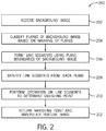
- FIG. 2 depicts an example of a process for performing a vanishing point calculation operation on a background image, according to certain embodiments of the present disclosure.
- FIG. 3 depicts an example of a process for selecting a set of line segments of a background image for use in a vanishing point calculation, according to certain embodiments of the present disclosure.
- FIG. 4 depicts an example of a process for performing k cross validation to validate a vanishing point calculation, according to certain embodiments of the present disclosure.
- FIG. 5 depicts an example of a background image with a single vanishing point, according to certain embodiments of the present disclosure.
- FIG. 6 depicts an example of the background image of FIG. 2 with identified planes, according to certain embodiments of the present disclosure.
- FIG. 7 depicts an example of a process for manipulating a feature image on a background image, according to certain embodiments of the present disclosure.
- FIG. 8 depicts an example of an output blended image including feature images, according to certain embodiments of the present disclosure.
- FIG. 9 depicts an example of a computing system for performing various operations described herein, according to certain embodiments of the present disclosure.
- Certain embodiments involve computing a vanishing point location in a background image by single vanishing points by excluding, from a vanishing point calculation, extraneous line segments in the image that do not converge to the single vanishing point.
- conventional solutions for locating vanishing points expend significant amounts of processing power by, for example, using every straight line segment in a background image to compute a vanishing point, even if the line segment does not converge to the vanishing point.
- images may contain an abundance of straight lines, and a significant percentage of the straight lines may not be valuable when determining the vanishing point, the resulting vanishing point computations may not be accurate even when these significant processing resources are expended.
- Certain embodiments described herein address this issue by, for example, paring down a number of line segments of a background image used to locate the vanishing point. For instance, a vanishing point calculator described herein focuses on line segments that converge toward a vanishing point and ignores other, extraneous line segments. By relying on a limited number of line segments, the vanishing point calculator is able to calculate the location of the vanishing point using a reduced amount of processing bandwidth as compared to certain conventional solutions described above. And eliminating extraneous line segments improves the accuracy of the vanishing-point computation by eliminating reliance on line segments that are likely irrelevant, and potentially disruptive, to the computation.
- an image manipulation system having one or more processing devices executes an image manipulation module to manipulate images received by the image manipulation system.
- the image manipulation system receives a background image representing a location receptive to overlaid feature images.
- An example of the background image is a sparsely decorated interior room with a single vanishing point.
- the image manipulation module classifies a set of planes present in the background image.
- the planes are representative of a floor, a ceiling, and any number of walls depicted within the background image. A number of boundaries between the planes form line segments with slopes directed to the single vanishing point location of the background image.
- the image manipulation module identifies a first set of line segments using the plane boundaries of the set of planes (e.g., by applying a watershed algorithm on the background image). Plane boundaries that are perpendicular or parallel with a horizontal axis of the background image are excluded from the first set of line segments, as such plane boundaries are irrelevant to a determination of the single vanishing point location.
- the image manipulation module identifies a second set of line segments positioned within individual planes of the set of planes that also include slopes directed to the single vanishing point location of the background image.
- the second set of line segments excludes line segments with slopes greater than +1 and less than ⁇ 1, as such line segments are unlikely to be relevant to the determination of the single vanishing point location.
- the second set of line segments include wall molding, trim work, door jambs and headers, and any other objects that form lines within the plane boundaries of the background image.
- the image manipulation module also groups first convergence points of the first set of line segments and second convergence points of the second set of line segments into a cluster.
- the image manipulation module computes the vanishing point location from an average of point locations in the cluster. Based on the average of the point locations in the cluster, the image manipulation module returns the vanishing point location. Using the vanishing point location, the image manipulation module manipulates a feature image overlaid on the background image. The image manipulation module manipulates the feature image by applying a scaling operation or a perspective warping operation on the feature image in such a manner that the feature image includes the same perspective as the background image.
- blending is used to refer to any image-processing operation that combines a feature image with a background image.
- blending involves scaling and/or perspective warping a feature image to correspond with a vanishing point location of a background image.
- image is used to refer to graphical content from a photograph, a drawing, or some combination thereof. Any set of graphical content items (i.e., a feature image or other graphic and a background image or other graphic) can be automatically blended in accordance with one or more embodiments described herein.
- vanishing point is used to refer to a point on an image plane where two-dimensional projections of a set of parallel lines in three-dimensional space appear to converge.
- Applying matching perspective to an image (e.g., a feature image) overlaid on top of another image (e.g., a background image) involves matching vanishing points of the two images.
- image manipulation application is used to refer to one or more applications, online services, or combinations thereof that include tools for blending a background image and a feature image. Blending the two images includes matching perspectives and scales between the two images based on a location of a vanishing point of the background image.
- Certain embodiments described herein facilitate using automated image manipulation systems for determining vanishing point locations and manipulating images based on the vanishing point locations.
- the automated image manipulation systems include one or more processors capable of executing instructions associated with determining the vanishing point locations and manipulating images.
- the use of the vanishing point locations allows images overlaid on background images to have the same perspective as the background image.
- FIG. 1 depicts an example of a computing environment 100 for calculating a vanishing point to control image blending operations of a background image 102 and a feature image 104 .
- the computing environment includes an image manipulation application 106 , which is executed by one or more computing devices.
- the image manipulation application 106 includes a vanishing point calculator 108 , a blending engine 110 , and a feature manipulator 112 .
- the vanishing point calculator 108 receives the background image 102 to automatically generate a location of a vanishing point within the background image 102 .
- the background image 102 is an interior image and includes a single vanishing point.
- the image manipulation application 106 also receives the feature image 104 at the blending engine 110 , and the vanishing point calculator 108 provides the background image 102 and the location of the vanishing point to the blending engine 110 .
- the image manipulation application 106 receives the background image 102 at the blending engine 110 , while the vanishing point calculator 108 provides the location of the vanishing point to the blending engine 110 .
- the blending engine 110 positions the feature image 104 over the background image 102 .
- the feature image refers to an image of a feature (e.g., a picture frame, a piece of furniture, a ceiling fan, etc.) capable of providing additional complexity to the background image 102 .
- the image manipulation application 106 applies the feature manipulator 112 to the feature image 104 .
- the feature manipulator 112 enhances effectiveness of the blending engine 110 by applying scaling and perspective warping effects to the feature image 104 on the background image 102 .
- Scaling and perspective warping effects applied to the feature image 104 provide an optical appearance that the feature image 104 is within the background image 102 rather than merely on top of the background image 102 .
- the scaling and perspective warping effects are generated for the feature image 104 based on the location of the vanishing point of the background image 102 .
- the location of the vanishing point influences orientation of parallel lines of the feature image 104
- proximity of the feature image 104 to the vanishing point influences the scale of the feature image 104 . That is, as the feature image 104 moves closer to the vanishing point of the background image 102 , the size of the feature image 104 is reduced by the feature manipulator 112 .
- the feature manipulator 112 generates an output blended image 114 by applying the scaling and perspective warping effects to the feature image 104 based on a location of the feature image 104 on the background image 102 . For instance, the feature manipulator 112 changes how the effects are applied to the feature image 104 based on the positioning of the feature image 104 on the background image 102 .
- the output blended image 114 can be used for a wide range of applications, such as automatic blending generation and dynamic content blending (videos).
- the image manipulation application 106 is implemented in an online environment to generate the output blended image 114 .
- the online environment is an online catalog selling items that are represented by the feature images 104 . If a consumer wants to see how the item would look inside a room, the online environment can provide the consumer with a stock background image 102 or the consumer can upload a photograph of a room within a house of the consumer, for example. In either embodiment, the consumer is able to move the feature image 104 of the item being sold in the online catalog around the room to see, via the output blended image 114 , how the item will look within the room prior to purchasing the item.
- FIG. 2 depicts an example of a process 200 for performing a vanishing point operation for the background image 102 with a single vanishing point.
- One or more processing devices implement operations depicted in FIG. 2 by executing suitable program code (e.g., the image manipulation application 106 ).
- suitable program code e.g., the image manipulation application 106 .
- the process 200 is described with reference to certain examples depicted in the figures. Other implementations, however, are possible.
- the process 200 involves receiving a background image.
- One or more processing devices execute the image manipulation application 106 (or suitable other program code) to implement block 202 .
- executing the image manipulation application 106 causes one or more processing devices to receive or otherwise access the background image 102 that is stored in a non-transitory computer-readable medium.
- receiving or accessing the background image 102 involves communicating, via a data bus, suitable signals between a local non-transitory computer-readable medium and the processing device.
- receiving or accessing the background image 102 involves communicating, via a data network, suitable signals between a computing system that includes the non-transitory computer-readable medium and a computing system that includes the processing device.
- the process 200 involves classifying planes within the background image 102 .
- the planes of the background image 102 include any flat surfaces depicted in the image, such as a ceiling, a floor, walls, doors, etc.
- One or more processing devices execute the image manipulation application 106 to implement block 204 .
- executing the image manipulation application 106 causes the vanishing point calculator 108 to receive or otherwise access identification of the planes within the background image 102 .
- a user of a mobile device or a computer device manually identifies a location of a plane depicted in the background image 102 and assigns the plane with a description (e.g., ceiling, floor, left wall, right wall, back wall, etc.).
- the processing device automatically locates planes within the background image 102 and assigns the planes with a description based on locations of the planes within the image.
- a watershed segmentation operation is applied to the background image 102 by the processing device to identify boundaries of the identified planes within the background image 102 .
- the watershed segmentation operation transforms the background image 102 to grayscale and treats gradient magnitudes of pixels as a topographic surface.
- the pixels within the background image 102 with a highest gradient magnitude intensity corresponds to a watershed line.
- a location or path of the watershed line represents a boundary between the planes identified in the background image 102 .
- Other techniques are also usable to find plane boundaries within the background image 102 .
- Defining the planes of the background image 102 with the description may correspond to how the feature image 104 is viewed when overlaid on the background image 102 .
- the image manipulation application 106 includes instructions that restrict the feature image 104 from being overlaid on a ceiling or a floor of the background image 102 .
- Other image rules relating to placement of the feature image 104 on the background image 102 are also available as part of the image manipulation application 106 .
- the process 200 involves forming line segments using plane boundaries of a background image. For instance, executing the image manipulation application 106 causes the vanishing point calculator 108 to form line segments of the background image 102 from the plane boundaries determined using the watershed segmentation operation or other technique of block 204 .
- the plane boundaries provide a set of line segments with slopes that converge on the vanishing point of the background image 102 .
- the process 200 involves identifying line segments from within planes of a background image. For instance, executing the image manipulation application 106 causes the vanishing point calculator 108 to identify line segments of the background image 102 that are within each of the identified plane boundaries determined using the watershed segmentation operation or other technique of block 204 .
- the line segments within the plane boundaries include wall molding, trim work, door jambs and headers, or any other objects that form lines within the plane boundaries.
- the line segments from within the plane boundaries of the background image 102 provide additional samples for the vanishing point calculator 108 to determine the vanishing point of the background image 102 .
- the process 200 involves performing an operation on identified line segments to determine the vanishing point. For instance, executing the image manipulation application 106 causes the vanishing point calculator 108 to locate a cluster of convergence points between each of the line segments of the background image 102 identified at blocks 206 and 208 , and to determine a location representative of a center point (e.g., an average location) of the cluster of the convergence points. The center point of the cluster of convergence points is used as the vanishing point of the background image 102 .
- the operation on the identified line segments is a k-means clustering operation, which is discussed in greater detail below with respect to FIG. 4 .
- the process 200 involves returning a vanishing point of a background image and manipulating a feature image based on the vanishing point.
- executing the image manipulation application 106 causes the vanishing point calculator 108 to return the vanishing point of the background image 102 based on a location of the center point of the cluster of convergence points calculated at block 210 .
- the vanishing point of the background image 102 is used in an example to manipulate the feature image 104 to blend the feature image 104 with the background image 102 .
- FIG. 3 depicts an example of a process 200 for selecting a set of line segments of the background image 102 for use in a vanishing point calculation.
- One or more processing devices implement operations depicted in FIG. 3 by executing suitable program code (e.g., the image manipulation application 106 ).
- suitable program code e.g., the image manipulation application 106 .
- the process 300 is described with reference to certain examples depicted in the figures. Other implementations, however, are possible.
- the process 300 involves initializing an empty set of line segments.
- One or more processing devices execute the image manipulation application 106 (or suitable other program code) to implement block 302 .
- executing the image manipulation application 106 causes one or more processing devices to reserve storage space in a non-transitory computer-readable medium for the set of line segments that will be identified by the vanishing point calculator 108 .
- the processing devices may limit a number of line segments that are available for use by the vanishing point calculator 108 to improve processing efficiency. For example, with a limited number of line segments, a smaller number of convergence points are calculated and the k-means operation considers the smaller number of convergence points when calculating the vanishing point of the background image 102 .
- the process 300 involves selecting plane boundaries for each plane for inclusion in the initialized set of line segments.
- the plane boundaries may be determined using a watershed segmentation operation or other technique capable of finding intersections between planes of an image. Particularly as it relates to a background image with minimal features (e.g., an interior of a cube), convergence locations of well-defined plane boundaries enable the vanishing point calculator 108 to accurately locate the vanishing point of the background image 102 .
- the vanishing point calculator 108 is able to provide an accurate prediction of the location of the vanishing point relying on only the plane boundaries of the background image 102 as the set of line segments.
- the process 300 involves discarding line segments perpendicular and parallel to a horizontal axis of an image. For instance, executing the image manipulation application 106 causes the vanishing point calculator 108 to discard line segments identified at block 304 that are perpendicular or parallel to a horizontal axis of the background image 102 .
- the line segments that are perpendicular or parallel to the horizontal axis of the background image 102 do not converge with other line segments at the vanishing point. Therefore, such line segments are not relevant to determining the vanishing point location of the background image 102 , and the line segments are removed to reduce processing power used by the image manipulation application 106 when calculating the location of the vanishing point.
- the process 300 involves adding the remaining plane boundaries to the set of line segments. For instance, executing the image manipulation application 106 causes the vanishing point calculator 108 to assign the remaining line segments to the memory location initialized at block 302 to hold the line segments.
- blocks 304 - 308 provide greater detail to an operation of block 206 , which is discussed above with respect to FIG. 2 .
- the process 300 involves locating and adding additional line segments with a slope of between +1 and ⁇ 1 to the set of line segments. For instance, executing the image manipulation application 106 causes the vanishing point calculator 108 to locate line segments located within the planes of the background image 102 with a slope between +1 and ⁇ 1. In an example, limiting the slope of the line segments to between +1 and ⁇ 1 removes a set of line segments that are more likely to not converge at the vanishing point of the background image 102 . Additionally, a number of line segments are discarded or ignored by limiting a range of the slope of the line segments. Discarding or ignoring line segments reduces processing power used to determine the location of the vanishing point of the background image 102 .
- block 310 provides greater detail to an operation of block 208 , which is discussed above with respect to FIG. 2 . Further, the discarding of line segments discussed above with respect to blocks 306 and 310 reduces overall computation costs associated with finding the vanishing point location of the background image 102 . For example, fewer line segments used to calculate the vanishing point location results in less computations performed by the vanishing point calculator 108 .
- the process 300 involves returning the set of line segments identified in the process 300 .
- executing the image manipulation application 106 causes the vanishing point calculator 108 to return the line segments identified in the background image 102 based on the criteria established in the process 300 .
- the set of line segments are usable by the vanishing point calculator 108 at block 210 , as discussed above, to determine a location of the vanishing point of the background image 102 .
- FIG. 4 depicts an example of a process 400 for performing k cross validation to validate a vanishing point calculation.
- One or more processing devices implement operations depicted in FIG. 4 by executing suitable program code (e.g., the image manipulation application 106 ).
- suitable program code e.g., the image manipulation application 106 .
- the process 400 is described with reference to certain examples depicted in the figures. Other implementations, however, are possible.
- the process 400 replaces or supplements block 210 discussed above with respect to FIG. 2 .
- the process 400 involves performing a k-means operation on 80% of the line segments (e.g., a calculation set) of the set of line segments returned at block 312 and an additional k-means operation on a remaining 20% of the line segments (e.g., a validation set) of the set of line segments.
- a k-means operation on 80% of the line segments (e.g., a calculation set) of the set of line segments returned at block 312 and an additional k-means operation on a remaining 20% of the line segments (e.g., a validation set) of the set of line segments.
- Other percentage partitions are also contemplated, and the line segments from the set of line segments are assigned to the calculation set or the validation set randomly.
- executing the image manipulation application 106 causes the vanishing point calculator 108 to partition the set of line segments of the background image 102 randomly into the 80% group and the 20% group.
- the vanishing point calculator 108 applies a first k-means operation to the 80% group and a second k-means operation to the 20% group.
- the first and second k-means operations generate two separate convergence point clusters and locate center points of the two separate convergence point clusters. If more than one cluster is generated for the 80% group and the 20% group, a convergence point cluster for each group with the smallest entropy and the largest number of convergence points is selected to represent the convergence point cluster used in the k-means operation.
- the process 400 involves determining if centers of the two separate convergence point clusters are less than a predefined number of units apart. For instance, executing the image manipulation application 106 causes the vanishing point calculator 108 to compare the center point of the 80% group convergence point cluster with the center point of the 20% group convergence point cluster.
- the image manipulation application 106 stores a value representative of a difference threshold between the two center points.
- the distance threshold provides a maximum acceptable difference between the two center points that results in a vanishing point of the background image 102 that is valid.
- the difference threshold value is representative of a number of pixels between the two center points of the convergence point clusters.
- the value of the difference threshold may increase or decrease based on an image quality of the background image 102 .
- the value of the difference threshold may be smaller than an embodiment with a lower image quality.
- the process 400 involves returning an indication that the calculated vanishing point is invalid when the center points of the convergence point clusters are greater than k units apart. For instance, executing the image manipulation application 106 causes the vanishing point calculator 108 to return an indication that the calculated vanishing point is not valid based on the distances between the center points exceeding the difference threshold value.
- the indication that the calculated vanishing point is invalid is provided to a user, it may indicate that the image includes multiple vanishing points. Accordingly, the invalid vanishing point indication may be accompanied by instructions to upload a new image with a single vanishing point.
- the process 400 involves returning an indication that the calculated vanishing point is valid when the center points of the convergence point clusters are less than k units apart. For instance, executing the image manipulation application 106 causes the vanishing point calculator 108 to return an indication that the calculated vanishing point is valid because the distances between the center points do not exceed the difference threshold value.
- the vanishing point calculator 108 returns the valid vanishing point location
- the vanishing point location which is represented by an average convergence location of the calculation set cluster, may be used to manipulate the feature image 104 using the feature manipulator 112 , as discussed below with respect to FIG. 7 .
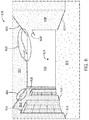
- FIG. 5 depicts an example of a background image 500 with a single vanishing point.
- interior images include a single vanishing point.
- the single vanishing point of an interior image allows the image manipulation application 106 to ignore a number of line segments within the background image 500 that are not relevant to calculating a location of the vanishing point within the background image 500 .
- the background image includes a set of planes including a ceiling 502 , a floor 504 , a left wall 506 , a right wall 508 , and a back wall 510 . In one example, other planes may also be identified, such as windows 512 and a hallway wall 514 , during block 204 of the process 200 .
- Line segments used to calculate the vanishing point location originate from boundaries between the planes, and line segments located within the planes. For example, line segments 516 , 518 , 520 , and 522 , which are all line segments made from boundaries between planes, all converge on a point 524 that is representative of a location of the vanishing point.
- Each plane of the set of planes is classified manually (e.g., using a point and click operation of a computing device) or intelligently (e.g., one or more processors executing instructions are able to identify planes based on a set of rules).
- a description is applied to the plane and certain rules are associated with the description.
- the feature image 104 when the feature image 104 is a piece of furniture, the feature image 104 is only able to be placed on the background image over a plane with a description of “floor.” Likewise, when the feature image 104 is a picture frame, the feature image 104 is only able to be placed on a plane with a description of “wall.” Other rules for placing the feature image 104 on a plane are also contemplated within the scope of the present disclosure.
- FIG. 6 depicts an example of a background image 600 with identified planes.
- the background image 600 is the background image 102 depicted in FIG. 5 after the background image 102 undergoes a watershed segmentation operation.
- a location on each of the planes is classified (e.g., a location of a mouse click on the ceiling 502 , the floor 504 , the left wall 506 , the right wall 508 , the back wall 510 , or any combination thereof)
- the watershed segmentation operation identifies the plane boundaries, as discussed in detail above with respect to FIG. 2 .
- the watershed segmentation operation also classifies portions of the image into the classified planes of the background image 102 .
- the watershed operation assigns all of the pixels within plane boundaries to one of the identified planes.
- the ceiling 502 , the floor 504 , the left wall 506 , the right wall 508 , and the back wall 510 are highlighted and assigned to corresponding planes.
- the background image 600 also depicts pixel bleeding 602 and 604 from one plane into another plane.
- the pixel bleeding 602 and 604 is a result of an image quality of the background image 102 .
- the planes defined by the water segmentation operation may bleed across the actual plane boundaries of the background image 102 .
- line segments associated with plane boundaries that do not generate a straight line e.g., due to the pixel bleeding 602 and 604
- all of the line segments associated with plane boundaries that generate straight lines may be used in accordance with the process 300 , which is discussed above with respect to FIG. 2 .
- the point 524 which represents a location of the vanishing point of the background image 600 , is determined using line segments 606 , 608 , 610 , 612 , 614 , 616 , and 618 .
- the line segments 606 - 618 are associated with plane boundaries generated by the watershed segmentation operation that form straight lines and also fit within the process 300 described above with respect to FIG. 3 .
- the vertical and horizontal plane boundaries identified by the watershed segmentation operation are not used to determine the vanishing point.
- the planes identified by the watershed segmentation operation include additional line segments within the planes (e.g., from wall molding, trim work, door jambs and headers, or any other objects that form lines within the plane boundaries)
- the additional line segments are also usable as additional reference points in determining the location of the vanishing point.
- the vanishing point calculator 108 uses the additional line segments from within the boundaries of the planes to identify additional convergence points used in the k-means operations.
- FIG. 7 depicts an example of a process 700 for manipulating a feature image on a background image.
- One or more processing devices implement operations depicted in FIG. 7 by executing suitable program code (e.g., the image manipulation application 106 ).
- suitable program code e.g., the image manipulation application 106 .
- the process 700 is described with reference to certain examples depicted in the figures. Other implementations, however, are possible.
- the process 700 involves receiving or otherwise accessing a feature image. For instance, executing the image manipulation application 106 causes the blending engine 110 to receive the feature image 104 .
- the feature image 104 is received when the feature image is placed over a portion of the background image 102 .
- the feature image 104 may be placed on a default location of the background image 102 for further placement by a user.
- the process 700 involves detecting a plane of a background image on which the feature image is applied. For instance, executing the image manipulation application 106 causes the blending engine 110 to detect a plane of the background image 102 on which the feature image 104 is positioned. In one example each feature image 104 is manipulated in a different manner by the feature manipulator 112 depending on which plane of the background image 102 the feature image 104 is positioned.
- the process 700 involves manipulating a feature image based on a vanishing point location of a background image. For instance, executing the image manipulation application 106 causes the feature manipulator 112 to manipulate the feature image 104 based on the vanishing point location of the background image 102 that is calculated by the vanishing point calculator 108 . Manipulating the feature image 104 completes the blending process when the image manipulation application 106 places the feature image 104 over the background image 102 . When the feature image 104 is placed over the background image 102 , the feature image 104 is moved, scaled, perspective warped, or any combination thereof by the feature manipulator 112 .
- the feature image 104 is a picture frame and is not able to be positioned on a plane representing the ceiling 502 or the floor 504 . Accordingly, when the feature image 104 is positioned over the ceiling 502 or the floor 504 by a user of the image manipulation application 106 , the feature manipulator 112 repositions the feature image 104 to a location on one of the walls 506 , 508 , or 510 that is closest to the original positioning of the picture frame.
- Other feature images 104 include similar placement limitations. For example, furniture is only able to be placed on the floor 504 , and a ceiling fan is only able to be placed on the ceiling 502 .
- a scaling operation and a perspective warping operation are also provided by the feature manipulator 112 .
- the perspective warping operation provided by the feature manipulator 112 changes a shape of the feature image 104 such that the line segments associated with a top boundary of the picture frame and a bottom boundary of the picture frame are directed at the vanishing point of the background image.
- a scaling operation provided by the feature manipulator 112 changes a size of the feature image 104 based on proximity of the feature image to the vanishing point of the background image 102 .
- the further away the picture frame on the right wall 508 is from the back wall 510 the larger the picture frame will be in the output blended image 114 .
- FIG. 8 depicts an example of an output blended image 800 from the image manipulation application 106 including manipulated feature images 104 .
- the feature image 104 A is a piece of framed artwork
- the feature image 104 B is a ceiling fan.
- Each of the feature images 104 A and 104 B include positioning rules that prohibit the feature images 104 A and 104 B from being positioned over portions of the background image 102 that would not work in a realistic scenario.
- the feature image 104 A may only be positioned on the walls 506 , 508 , and 510
- the feature image 104 B may only be positioned on the ceiling 502 .
- the feature image 104 A is both scaled and perspective warped. For example, an upper line segment 802 and a lower line segment 804 are both warped in such a manner that the upper line segment 802 and the lower line segment 804 point toward the point 524 representative of the vanishing point. Additionally, as the feature image 104 A is moved in a direction 806 along the wall 508 , a size of the feature image 104 A increases based on the scaling of the feature manipulator 112 . Similarly, as the feature image 104 A is move in a direction 808 along the wall 508 , the size of the feature image 104 A decreases as the feature image 104 A is perceived to move further away from an observer of the output blended image 800 .
- Some feature images 104 do not include line segments that rely on perspective warping for the feature image 104 to look correct when placed over the background image 102 .
- the feature image 104 B which is a ceiling fan, does not include line segments that rely on perspective warping.
- the feature image 104 B remains affected by scaling issues. For example, as the feature image 104 B moves in a direction 810 , the feature image 104 B increases in size such that an observer of the output blended image 800 has the perception that the feature image 104 B is closer to the observer. Similarly, as the feature image 104 B moves in a direction 812 , the feature image 104 B decreases in size such that the observer of the output blended image 800 has the perception that the feature image 104 B is further away from the observer.
- FIG. 9 depicts an example of a computing system 900 for performing various operations described herein, according to certain embodiments of the present disclosure.
- the computing system 900 executes the image manipulation application 106 , as depicted in FIG. 9 .
- separate computing systems having devices similar to those depicted in FIG. 9 (e.g., a processor, a memory, etc.) separately execute the image manipulation application 106 .
- the depicted example of a computing system 900 includes a processor 902 communicatively coupled to one or more memory devices 904 .
- the processor 902 executes computer-executable program code stored in a memory device 904 , accesses information stored in the memory device 904 , or both.
- Examples of the processor 902 include a microprocessor, an application-specific integrated circuit (“ASIC”), a field-programmable gate array (“FPGA”), or any other suitable processing device.
- the processor 902 can include any number of processing devices, including a single processing device.
- the memory device 904 includes any suitable non-transitory computer-readable medium for storing data, program code, or both.
- a computer-readable medium can include any electronic, optical, magnetic, or other storage device capable of providing a processor with computer-readable instructions or other program code.
- Non-limiting examples of a computer-readable medium include a magnetic disk, a memory chip, a ROM, a RAM, an ASIC, optical storage, magnetic tape or other magnetic storage, or any other medium from which a processing device can read instructions.
- the instructions may include processor-specific instructions generated by a compiler or an interpreter from code written in any suitable computer-programming language, including, for example, C, C++, C #, Visual Basic, Java, Python, Perl, JavaScript, and ActionScript.
- the computing system 900 may also include a number of external or internal devices, such as input or output devices.
- the computing system 900 is shown with one or more input/output (“I/O”) interfaces 908 .
- I/O interface 908 can receive input from input devices or provide output to output devices.
- One or more buses 906 are also included in the computing system 900 .
- the bus 906 communicatively couples one or more components of a respective one of the computing system 900 .
- the computing system 900 executes program code that configures the processor 902 to perform one or more of the operations described herein.
- the program code includes, for example, the image manipulation application 106 , the vanishing point calculator 108 , the blending engine 110 , the feature manipulator 112 , or other suitable applications that perform one or more operations described herein.
- the program code may be resident in the memory device 904 or any suitable computer-readable medium and may be executed by the processor 902 or any other suitable processor.
- the program code described above is stored in one or more other memory devices accessible via a data network.
- the computing system 900 also includes a network interface device 910 .
- the network interface device 910 includes any device or group of devices suitable for establishing a wired or wireless data connection to one or more data networks.
- Non-limiting examples of the network interface device 910 include an Ethernet network adapter, a modem, and/or the like.
- the computing system 900 is able to communicate with one or more other computing devices (e.g., a computing device executing an image manipulation application 106 ) via a data network using the network interface device 910 .
- the computing system 900 also includes the presentation device 912 .
- a presentation device 912 can include any device or group of devices suitable for providing visual, auditory, or other suitable sensory output. Non-limiting examples of the presentation device 912 include a touchscreen, a monitor, a speaker, a separate mobile computing device, etc.
- the presentation device 912 can include a remote client-computing device that communicates with the computing system 900 using one or more data networks described herein. Other aspects can omit the presentation device 912 .
- a computing device can include any suitable arrangement of components that provide a result conditioned on one or more inputs.
- Suitable computing devices include multi-purpose microprocessor-based computer systems accessing stored software that programs or configures the computing system from a general purpose computing apparatus to a specialized computing apparatus implementing one or more embodiments of the present subject matter. Any suitable programming, scripting, or other type of language or combinations of languages may be used to implement the teachings contained herein in software to be used in programming or configuring a computing device.
- Embodiments of the methods disclosed herein may be performed in the operation of such computing devices.
- the order of the blocks presented in the examples above can be varied—for example, blocks can be re-ordered, combined, and/or broken into sub-blocks. Certain blocks or processes can be performed in parallel.
Abstract
Description
Claims (19)
Priority Applications (1)
| Application Number | Priority Date | Filing Date | Title |
|---|---|---|---|
| US15/972,779 US10776973B2 (en) | 2018-05-07 | 2018-05-07 | Vanishing point computation for single vanishing point images |
Applications Claiming Priority (1)
| Application Number | Priority Date | Filing Date | Title |
|---|---|---|---|
| US15/972,779 US10776973B2 (en) | 2018-05-07 | 2018-05-07 | Vanishing point computation for single vanishing point images |
Publications (2)
| Publication Number | Publication Date |
|---|---|
| US20190340798A1 US20190340798A1 (en) | 2019-11-07 |
| US10776973B2 true US10776973B2 (en) | 2020-09-15 |
Family
ID=68383871
Family Applications (1)
| Application Number | Title | Priority Date | Filing Date |
|---|---|---|---|
| US15/972,779 Active 2038-07-12 US10776973B2 (en) | 2018-05-07 | 2018-05-07 | Vanishing point computation for single vanishing point images |
Country Status (1)
| Country | Link |
|---|---|
| US (1) | US10776973B2 (en) |
Families Citing this family (1)
| Publication number | Priority date | Publication date | Assignee | Title |
|---|---|---|---|---|
| CN112614074B (en) * | 2020-12-28 | 2022-11-11 | 自行科技(武汉)有限公司 | Robust vanishing point detection method and device based on response graph and clustering |
Citations (7)
| Publication number | Priority date | Publication date | Assignee | Title |
|---|---|---|---|---|
| US6778699B1 (en) | 2000-03-27 | 2004-08-17 | Eastman Kodak Company | Method of determining vanishing point location from an image |
| US20060244749A1 (en) * | 2005-04-28 | 2006-11-02 | Sony Corporation | Image processing apparatus, image processing method, and program and recording medium used therewith |
| US8396285B2 (en) * | 2009-04-20 | 2013-03-12 | Hewlett-Packard Development Company, L.P. | Estimating vanishing points in images |
| US20150160539A1 (en) * | 2013-12-09 | 2015-06-11 | Geo Semiconductor Inc. | System and method for automated test-pattern-free projection calibration |
| US20150332117A1 (en) * | 2014-05-13 | 2015-11-19 | The Penn State Research Foundation | Composition modeling for photo retrieval through geometric image segmentation |
| US20170084081A1 (en) * | 2015-09-17 | 2017-03-23 | Ricoh Company, Ltd. | Image processing device, image processing method, and recording medium |
| US20170352192A1 (en) * | 2014-11-16 | 2017-12-07 | Eonite Perception Inc. | Systems and methods for augmented reality preparation, processing, and application |
-
2018
- 2018-05-07 US US15/972,779 patent/US10776973B2/en active Active
Patent Citations (8)
| Publication number | Priority date | Publication date | Assignee | Title |
|---|---|---|---|---|
| US6778699B1 (en) | 2000-03-27 | 2004-08-17 | Eastman Kodak Company | Method of determining vanishing point location from an image |
| US20060244749A1 (en) * | 2005-04-28 | 2006-11-02 | Sony Corporation | Image processing apparatus, image processing method, and program and recording medium used therewith |
| US8396285B2 (en) * | 2009-04-20 | 2013-03-12 | Hewlett-Packard Development Company, L.P. | Estimating vanishing points in images |
| US20150160539A1 (en) * | 2013-12-09 | 2015-06-11 | Geo Semiconductor Inc. | System and method for automated test-pattern-free projection calibration |
| US20180196336A1 (en) * | 2013-12-09 | 2018-07-12 | Geo Semiconductor Inc. | System and method for automated test-pattern-free projection calibration |
| US20150332117A1 (en) * | 2014-05-13 | 2015-11-19 | The Penn State Research Foundation | Composition modeling for photo retrieval through geometric image segmentation |
| US20170352192A1 (en) * | 2014-11-16 | 2017-12-07 | Eonite Perception Inc. | Systems and methods for augmented reality preparation, processing, and application |
| US20170084081A1 (en) * | 2015-09-17 | 2017-03-23 | Ricoh Company, Ltd. | Image processing device, image processing method, and recording medium |
Also Published As
| Publication number | Publication date |
|---|---|
| US20190340798A1 (en) | 2019-11-07 |
Similar Documents
| Publication | Publication Date | Title |
|---|---|---|
| US10373380B2 (en) | 3-dimensional scene analysis for augmented reality operations | |
| US11869161B2 (en) | Overlaying 3D augmented reality content on real-world objects using image segmentation | |
| US20200126298A1 (en) | Methods and systems for detecting and combining structural features in 3d reconstruction | |
| CN108895981B (en) | Three-dimensional measurement method, device, server and storage medium | |
| US10235771B2 (en) | Methods and systems of performing object pose estimation | |
| KR102647351B1 (en) | Modeling method and modeling apparatus using 3d point cloud | |
| JP5822322B2 (en) | Network capture and 3D display of localized and segmented images | |
| US11113571B2 (en) | Target object position prediction and motion tracking | |
| US11170246B2 (en) | Recognition processing device, recognition processing method, and program | |
| US9208606B2 (en) | System, method, and computer program product for extruding a model through a two-dimensional scene | |
| EP3321845A1 (en) | Ship identification system and method | |
| US11651533B2 (en) | Method and apparatus for generating a floor plan | |
| EP4107650A1 (en) | Systems and methods for object detection including pose and size estimation | |
| GB2563596A (en) | System and method for modeling a three dimensional space based on a two dimensional image | |
| US10776973B2 (en) | Vanishing point computation for single vanishing point images | |
| CN106910196B (en) | Image detection method and device | |
| CN113989376B (en) | Method and device for acquiring indoor depth information and readable storage medium | |
| US11281935B2 (en) | 3D object detection from calibrated 2D images | |
| CN113191462A (en) | Information acquisition method, image processing method and device and electronic equipment | |
| WO2021160097A1 (en) | System and method for object detection for augmented reality | |
| Alami et al. | Vanishing Point Detection Under Foggy Weather with Edge-Based Approach | |
| Aman | Model-Based Camera Tracking for Augmented Reality |
Legal Events
| Date | Code | Title | Description |
|---|---|---|---|
| AS | Assignment |
Owner name: ADOBE SYSTEMS INCORPORATED, CALIFORNIA Free format text: ASSIGNMENT OF ASSIGNORS INTEREST;ASSIGNOR:GARG, SAURABH;REEL/FRAME:045733/0824 Effective date: 20180504 |
|
| FEPP | Fee payment procedure |
Free format text: ENTITY STATUS SET TO UNDISCOUNTED (ORIGINAL EVENT CODE: BIG.); ENTITY STATUS OF PATENT OWNER: LARGE ENTITY |
|
| AS | Assignment |
Owner name: ADOBE INC., CALIFORNIA Free format text: CHANGE OF NAME;ASSIGNOR:ADOBE SYSTEMS INCORPORATED;REEL/FRAME:048525/0042 Effective date: 20181008 |
|
| STPP | Information on status: patent application and granting procedure in general |
Free format text: RESPONSE TO NON-FINAL OFFICE ACTION ENTERED AND FORWARDED TO EXAMINER |
|
| STPP | Information on status: patent application and granting procedure in general |
Free format text: NON FINAL ACTION MAILED |
|
| STPP | Information on status: patent application and granting procedure in general |
Free format text: PUBLICATIONS -- ISSUE FEE PAYMENT VERIFIED |
|
| STCF | Information on status: patent grant |
Free format text: PATENTED CASE |
|
| MAFP | Maintenance fee payment |
Free format text: PAYMENT OF MAINTENANCE FEE, 4TH YEAR, LARGE ENTITY (ORIGINAL EVENT CODE: M1551); ENTITY STATUS OF PATENT OWNER: LARGE ENTITY Year of fee payment: 4 |