US1077458A - Machine for molding metal in indeterminate lenghts. - Google Patents
Machine for molding metal in indeterminate lenghts. Download PDFInfo
- Publication number
- US1077458A US1077458A US60609411A US1911606094A US1077458A US 1077458 A US1077458 A US 1077458A US 60609411 A US60609411 A US 60609411A US 1911606094 A US1911606094 A US 1911606094A US 1077458 A US1077458 A US 1077458A
- Authority
- US
- United States
- Prior art keywords
- machine
- wheel
- band
- die
- metal
- Prior art date
- Legal status (The legal status is an assumption and is not a legal conclusion. Google has not performed a legal analysis and makes no representation as to the accuracy of the status listed.)
- Expired - Lifetime
Links
- 239000002184 metal Substances 0.000 title description 15
- 238000000465 moulding Methods 0.000 title description 9
- 238000010276 construction Methods 0.000 description 5
- 230000002093 peripheral effect Effects 0.000 description 3
- 238000002844 melting Methods 0.000 description 2
- 230000008018 melting Effects 0.000 description 2
- 229910000831 Steel Inorganic materials 0.000 description 1
- 230000002844 continuous effect Effects 0.000 description 1
- 239000012530 fluid Substances 0.000 description 1
- 239000000463 material Substances 0.000 description 1
- 238000000034 method Methods 0.000 description 1
- 238000005096 rolling process Methods 0.000 description 1
- 239000010959 steel Substances 0.000 description 1
Images
Classifications
-
- B—PERFORMING OPERATIONS; TRANSPORTING
- B22—CASTING; POWDER METALLURGY
- B22D—CASTING OF METALS; CASTING OF OTHER SUBSTANCES BY THE SAME PROCESSES OR DEVICES
- B22D11/00—Continuous casting of metals, i.e. casting in indefinite lengths
- B22D11/06—Continuous casting of metals, i.e. casting in indefinite lengths into moulds with travelling walls, e.g. with rolls, plates, belts, caterpillars
- B22D11/0637—Accessories therefor
- B22D11/0677—Accessories therefor for guiding, supporting or tensioning the casting belts
Definitions
- Sheet lead has usually been made by a continuous rolling process. This is comparatively slow and necessarily expensive and usually necessitates passing the material through the rollers a number of times.
- the object of this invention is to afford a machinev for making sheet lead by what might be termed a continuous molding process. and in which the sheet is fed from the mold as rapidly as formed- It is also an object of the invention to afford a machine for making sheet lead by delivering the molten lead into a mold aflorded by two coacting constantly moving members. affording the walls of the mold.
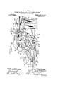
- Figure 1 is a view in elevation of the driving side of the machine.
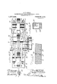
- Fig. 2 is a top plan view thereof with the supply pipe omitted.
- Fig. 3 is a rear end elevation.
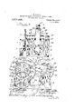
- Fig. 4 is a side elevation of a slightly modified construction.
- Fig. 5- is an enlarged section taken through line 5-5 of F 1.
- Fig. 6 is an enlarged fragmentary section of the feed receptacle and the adjusting means for the discharge therefrom.
- 1,indicatcs the side members of the frame of the machine affor an upwardly extending standard.
- a shaft 4 provided on the driving side of the machine at one end thereof with a gear wheel 5, which meshes with a pinion 6, as shown in Fig. 1, which is rigidly connected with thedrivin or belt wheel 7, secured on the driving sha t S, which may be a non-rotative stud shaft rigidly secured on the side frame member 2, at the driving side of the machine.
- the die wheel 9 Rigidly secured on the. shaft 4, to revolve therewith, is the die wheel 9, of relatively large diameter and provided with a peripheral groove. 9 in the face thereof, as shown in Figs. 1, 2 and 3 of the width and of the depth of the sheet or strip of metal to be formed.
- an adjustable bearing 10 Slidably secured on the standards 3, at the front end of the machine, is an adjustable bearing 10, in which is journaled a shaft 11, and on which is rigidly secured a flat faced wheel or pulley 12, the width of the face of which is approximately equal to the face of the die wheel 9.
- adjusting screws 13 are provided in the top of the standard to bear against said bearing block 10, to adjustthe same thereon toward or from the dic wheel.
- yoke 14- Pivotally engaged on the rear end of the frame is a yoke 14-, provided at its outer or rear end with a counterweight 15. Journaled on the shaft 4, on each side of the die wheel arc rear'wardly extending arms 16,
- rovidcd at their lower or rear ends with a ongitudiually slotted aperture in which is journalcd a shaft- 17.
- a follower or shoe 18 bears against the outer side of the shaft and an adjusting screw or bolt 19, extends through the head of said arm and bears ainst said shoe to press the same toward t 1e die wheel.
- lligidly secured on said shaft is a rear belt or band wheel 20, similar to the band wheel 12, and which also is of a width of face corresponding approx mately with the width of the face of the die wheel.
- a steel or other metallic non-combustible belt 21, is trained about the belt wheels 12 and 20, and the upper lap thereof extends around the lower portion of the die wheel and affords the bottom of the mold for the sheet or strip as shown in Fig. 5.
- Secured on each of the arms 16, and integral therewith is an inclined rib or cam face 22, and a crank 23 is provided on each of the ends of the yoke 14, at the pivot therefor and bears against the under side of said rib or cam 22, and acts to hold said lever or arm upwardly to maintain tension on the belt.
- a melting pot (which is not shown in the drawings) is supported at any convenient point adjacent the machine and preferably above the same, and a pipe 2&, is connected therein and leads to a point above a feed trough 25, shaped to fit closely in the space between the die wheel and the belt 21,where the latter is trained over the band wheel 12, as shown in Fig. 1.
- Said feed receptacle or trough is supported in place by means of lateral brace bars 26, one of which is secured on each end of the trough at each side of the wheel and extends rearwardly and is secured to the standard 2.
- a narrow slot 25 is provided through the rear side of said trough near the bottom thereof to direct the molten lead delivered thereinto from the pipe 24:,
- a shutter or plate 27 is provided in the rear side of said trough and is slidably adjustable to vary or limit the discharge orifice 25 therefrom to the die wheel.
- a Bunsen burner 28 is provided at each end of the trough and connected with any suitable source of gas supply. Said burners act to maintain the temperature of the trough at the desired point to avoid the chilling of the metal when delivered thereinto and to insure the continuance of the most advantageous conditions under which the machine can work.
- the operation is as follows: The lead is brought to the required or standard temperature and the receiving trough is first heated to the required temperature or to a temperature such that chilling of the metal will be avoided.
- the metal is then admitted into the trough from the pipe 24:, any suitable valve closely connected with the pot sufiicing for this purpose.
- the metal passes through the opening in said trough into the groove in the die wheel and is promptly cooled by contact with the die wheel and the metal belt and is simultaneously fed forwardly and through the machine and delivered in the form of a sheet ribbon or strip at the rear.
- Tension is at all times maintained on the belt by the counterweight attachment before described, which acts to elevate the tightener pulley or the band wheel 20.
- the construction is such that the machine may be driven at a high rate of speed and the metal sheet ribbon or strip rapidly formed and fed therefrom.
- a fixed plate 29 extends upwardly beneath the band wheel 12, and die wheel 9, and extends rearwardly and downwardly fitting closely to said die wheel,
- a rotatable die member having a peripheral recess therein, affording a mold, a continuous band affording a closure for the mold, and a plurality of band wheels adapted to guide said band, one of said wheels being revoluble about the die member.
- a pair of adjustable band wheels a shaft, a pair of arms journaled on said shaft and supporting one of the band wheels, a rotative die member rigidly secured to said shaft, and a band trained around said band wheels and a part of the die member.
- a frame a rotative die'member having a con tinuous peripheral recess therein to afford a mold, a pair of arms journaled coaxially with the rotative die member, a band wheel adjustably j ournaled therein, a second band wheel supported on said frame, and a band trained over said band wheels and a part of the rotatable die member, adapted to afford the closure for said mold.
- a frame consisting of a horizontal base and a long and a short pair of upright members, a driving shaft journaled on the long pair of said members, a rotatable die member rigidly secured to said shaft, a shaft journaled on the short pair of uprights, a I
Landscapes
- Engineering & Computer Science (AREA)
- Mechanical Engineering (AREA)
- Moulds For Moulding Plastics Or The Like (AREA)
Description
E5555 v I VET-1b lzjzwlfleflms I y G. W. DENNIS.
MACHINE FOR MOLDING METAL IN INDBTERMINATB LENGTHS.
IIIIIIIIIIIIIIIIIIIIIIII 1.
1,077,458. v PatentedNov.4,1913. I 3 EEEEEEEEEEEE 1.
G. W. DENNIS.
MACHINE FOR MOLDING METAL IN INDETBRMINATE LENGTHS.
APPLICATION FILED 1313.2, 1911.
Patented Nov. 4, 1913'.
w I 3 SHEETS-811E132- m N w G. W. DENNIS. MACHINE FOR MOLDING METAL, IN INDETERMINATE LENGTHS. APPLICATION FILED FEB. 2, 1911.
1,077,45 Patented m 4, 1913.
3 SHEETS-SHEET 3.
55 2, on eac GEORGE W. DENNIS, F HARVEY, ILLINOIS.
MACHINE FOR MOLDING METAL IN INDETERMINATE LENGTHS.
Specification of Letters Patent.
Patented Nov. a, 1913.
Application filed February 2, 1911. Serial No. 606,094.
To all whom it may concern:
Be it known that I, GEORGE W. DENNIS, a citizen of the United States, and a resident of the city of Harvey, in the county of Cook and State of Illinois, have invented certain new and useful Improvements in Machines for Molding Metal in Indeterminate Lengths; and I do hereby declare that the following is a full, clear, and exact description of the same, reference being had to the accompanying drawin s, and to the numbers of reference marked t ereon, which form a part of this specification.
Sheet lead has usually been made by a continuous rolling process. This is comparatively slow and necessarily expensive and usually necessitates passing the material through the rollers a number of times.
The object of this invention is to afford a machinev for making sheet lead by what might be termed a continuous molding process. and in which the sheet is fed from the mold as rapidly as formed- It is also an object of the invention to afford a machine for making sheet lead by delivering the molten lead into a mold aflorded by two coacting constantly moving members. affording the walls of the mold.
It is, of course, an objectof the invention 80.to enable a sheet or strip of any desired size or width to be made and to afford mechanism in connection with such a machine whereby suitable adjustments may be made in the mechanism to compensate for variations in 86 temperature either of the mechanism or of the molten metal, thus enabling a constant and uniform feed to be assuredv sufficient to keep the mold at all times filled. v
The invention consists in the matters hereinafter described and more fully pointed out and defined in the appended claims.
In the drawings: Figure 1 is a view in elevation of the driving side of the machine. Fig. 2 is a top plan view thereof with the supply pipe omitted. Fig. 3 is a rear end elevation. Fig. 4 is a side elevation of a slightly modified construction. Fig. 5- is an enlarged section taken through line 5-5 of F 1. Fig. 6 is an enlarged fragmentary section of the feed receptacle and the adjusting means for the discharge therefrom.
As shown in the drawings; 1,indicatcs the side members of the frame of the machine affor an upwardly extending standard.
side thereof near the rear end and corresponding upwardly extending standards 3, at the front end of the same. Journaled in suitable bearings at the top of the standards 2, is a shaft 4, provided on the driving side of the machine at one end thereof with a gear wheel 5, which meshes with a pinion 6, as shown in Fig. 1, which is rigidly connected with thedrivin or belt wheel 7, secured on the driving sha t S, which may be a non-rotative stud shaft rigidly secured on the side frame member 2, at the driving side of the machine.
Rigidly secured on the. shaft 4, to revolve therewith, is the die wheel 9, of relatively large diameter and provided with a peripheral groove. 9 in the face thereof, as shown in Figs. 1, 2 and 3 of the width and of the depth of the sheet or strip of metal to be formed.
Slidably secured on the standards 3, at the front end of the machine, is an adjustable bearing 10, in which is journaled a shaft 11, and on which is rigidly secured a flat faced wheel or pulley 12, the width of the face of which is approximately equal to the face of the die wheel 9. As shown, adjusting screws 13, are provided in the top of the standard to bear against said bearing block 10, to adjustthe same thereon toward or from the dic wheel.
Pivotally engaged on the rear end of the frame is a yoke 14-, provided at its outer or rear end with a counterweight 15. Journaled on the shaft 4, on each side of the die wheel arc rear'wardly extending arms 16,
rovidcd at their lower or rear ends with a ongitudiually slotted aperture in which is journalcd a shaft- 17. As shown, a follower or shoe 18, bears against the outer side of the shaft and an adjusting screw or bolt 19, extends through the head of said arm and bears ainst said shoe to press the same toward t 1e die wheel. lligidly secured on said shaft is a rear belt or band wheel 20, similar to the band wheel 12, and which also is of a width of face corresponding approx mately with the width of the face of the die wheel.
A steel or other metallic non-combustible belt 21, is trained about the belt wheels 12 and 20, and the upper lap thereof extends around the lower portion of the die wheel and affords the bottom of the mold for the sheet or strip as shown in Fig. 5. Secured on each of the arms 16, and integral therewith is an inclined rib or cam face 22, and a crank 23 is provided on each of the ends of the yoke 14, at the pivot therefor and bears against the under side of said rib or cam 22, and acts to hold said lever or arm upwardly to maintain tension on the belt.
A melting pot (which is not shown in the drawings) is supported at any convenient point adjacent the machine and preferably above the same, and a pipe 2&, is connected therein and leads to a point above a feed trough 25, shaped to fit closely in the space between the die wheel and the belt 21,where the latter is trained over the band wheel 12, as shown in Fig. 1. Said feed receptacle or trough is supported in place by means of lateral brace bars 26, one of which is secured on each end of the trough at each side of the wheel and extends rearwardly and is secured to the standard 2. A narrow slot 25 is provided through the rear side of said trough near the bottom thereof to direct the molten lead delivered thereinto from the pipe 24:,
into the groove or channel in the die wheel,
and, as shown, a shutter or plate 27, is provided in the rear side of said trough and is slidably adjustable to vary or limit the discharge orifice 25 therefrom to the die wheel.
As shown, a Bunsen burner 28, is provided at each end of the trough and connected with any suitable source of gas supply. Said burners act to maintain the temperature of the trough at the desired point to avoid the chilling of the metal when delivered thereinto and to insure the continuance of the most advantageous conditions under which the machine can work.
The operation is as follows: The lead is brought to the required or standard temperature and the receiving trough is first heated to the required temperature or to a temperature such that chilling of the metal will be avoided. The metal is then admitted into the trough from the pipe 24:, any suitable valve closely connected with the pot sufiicing for this purpose. The metal passes through the opening in said trough into the groove in the die wheel and is promptly cooled by contact with the die wheel and the metal belt and is simultaneously fed forwardly and through the machine and delivered in the form of a sheet ribbon or strip at the rear. Tension is at all times maintained on the belt by the counterweight attachment before described, which acts to elevate the tightener pulley or the band wheel 20. The construction is such that the machine may be driven at a high rate of speed and the metal sheet ribbon or strip rapidly formed and fed therefrom.
The construction shown in Fig. 4, is the same as that before described with'the exception that in lieu of a belt affording one side of the die or mold, a fixed plate 29, extends upwardly beneath the band wheel 12, and die wheel 9, and extends rearwardly and downwardly fitting closely to said die wheel,
as shown in Fig. 4:, so that as the metal strip is formed and cooled, it is delivered rearwardly from the machine down said inclined plate.
Of course, detailsof the construction may be Varied in numerous ways and the exact construction of the receiving trough and feed pipe will be varied to a greater or less extent depending upon the width or form and size of the sheet or strip to be formed. Any suitable means may be used for melting the metal, the temperature of which must be such as to render the same sulficiently fluid to readily flow in and fill the mold in the die wheel, and the rate of delivery thereinto should be sufliciently rapid as to keep the mold filled as the strip is fed rearwardly, thereby producing a smooth strip of uniform consistency. I therefore do not purpose limiting the patentto be granted on this application otherwise than necessitated by the prior art.
I claim as my invention:
1. In a machine for molding metal in long strips, a rotatable die member having a peripheral recess therein, affording a mold, a continuous band affording a closure for the mold, and a plurality of band wheels adapted to guide said band, one of said wheels being revoluble about the die member.
2. In a machine for molding metal in long strips, a pair of adjustable band wheels, a shaft, a pair of arms journaled on said shaft and supporting one of the band wheels, a rotative die member rigidly secured to said shaft, and a band trained around said band wheels and a part of the die member.
3. In a device of the class described, a frame, a rotative die'member having a con tinuous peripheral recess therein to afford a mold, a pair of arms journaled coaxially with the rotative die member, a band wheel adjustably j ournaled therein, a second band wheel supported on said frame, and a band trained over said band wheels and a part of the rotatable die member, adapted to afford the closure for said mold.
4. In a machine for molding metal in long strips, a frame consisting of a horizontal base and a long and a short pair of upright members, a driving shaft journaled on the long pair of said members, a rotatable die member rigidly secured to said shaft, a shaft journaled on the short pair of uprights, a I
band wheel secured thereon, a pair of arms journaled on the driving shaft, a band wheel adjustably journaled in said arms adapted to be revolved about the die member, a band trained around said band wheels .and die I one pair of said members, means for driving In testimony whereof I have herefinto subsaid member, a band wheel adjustably scribed my name in the presence of two sub mounted on the other pair of said members, scribing Witnesses.
arms revoluble about said die member, the GEORGE W. DENNIS. second hand wheel adjustably mounted in Witnesses: J said arms, and a band trained over said band CHARLES W. HILLS, Jr.
wheels and under [the die member. ANNA B. Him-s.
Priority Applications (1)
| Application Number | Priority Date | Filing Date | Title |
|---|---|---|---|
| US60609411A US1077458A (en) | 1911-02-02 | 1911-02-02 | Machine for molding metal in indeterminate lenghts. |
Applications Claiming Priority (1)
| Application Number | Priority Date | Filing Date | Title |
|---|---|---|---|
| US60609411A US1077458A (en) | 1911-02-02 | 1911-02-02 | Machine for molding metal in indeterminate lenghts. |
Publications (1)
| Publication Number | Publication Date |
|---|---|
| US1077458A true US1077458A (en) | 1913-11-04 |
Family
ID=3145689
Family Applications (1)
| Application Number | Title | Priority Date | Filing Date |
|---|---|---|---|
| US60609411A Expired - Lifetime US1077458A (en) | 1911-02-02 | 1911-02-02 | Machine for molding metal in indeterminate lenghts. |
Country Status (1)
| Country | Link |
|---|---|
| US (1) | US1077458A (en) |
Cited By (2)
| Publication number | Priority date | Publication date | Assignee | Title |
|---|---|---|---|---|
| US2659948A (en) * | 1950-01-21 | 1953-11-24 | Properzi Ilario | Machine for the continuous casting of metal rods |
| US3318364A (en) * | 1966-03-21 | 1967-05-09 | Southwire Co | Band supporting means |
-
1911
- 1911-02-02 US US60609411A patent/US1077458A/en not_active Expired - Lifetime
Cited By (2)
| Publication number | Priority date | Publication date | Assignee | Title |
|---|---|---|---|---|
| US2659948A (en) * | 1950-01-21 | 1953-11-24 | Properzi Ilario | Machine for the continuous casting of metal rods |
| US3318364A (en) * | 1966-03-21 | 1967-05-09 | Southwire Co | Band supporting means |
Similar Documents
| Publication | Publication Date | Title |
|---|---|---|
| US1077458A (en) | Machine for molding metal in indeterminate lenghts. | |
| US2765768A (en) | Cement handling apparatus | |
| US1422532A (en) | Machine for making ornamental rules and borders | |
| US2019496A (en) | Apparatus for producing copper and other metal rods and the like | |
| US2677036A (en) | Arc-welding process and apparatus | |
| US704434A (en) | Paper-coating machine. | |
| US1666909A (en) | Bending machine | |
| US2091588A (en) | Babbitting apparatus | |
| US2136001A (en) | Machine for cutting bars of soap and other plastic material | |
| US805833A (en) | Machine for applying flux to cylindric bodies. | |
| US1325466A (en) | Papeb-bag-makijmg machine | |
| US1280139A (en) | Glass manufacture. | |
| US2065546A (en) | Method of and apparatus for producing cellular metal building units | |
| US1982697A (en) | Attachment for paper bag making machines | |
| US661025A (en) | Manufacture of prism-glass. | |
| US2146507A (en) | Coating machine | |
| US2291549A (en) | Apparatus for wire glass manufacture | |
| US876267A (en) | Process and apparatus for the continuous production of sheet-glass. | |
| US2009706A (en) | Method of and apparatus for making wire glass | |
| US901358A (en) | Machine for punching and trimming metal stay-strips for boxes. | |
| US1818207A (en) | Process of and apparatus for forming sheet glass | |
| US1577934A (en) | Candy-ribbon-forming machine | |
| US2062228A (en) | Method and device for producing single-layered wire glass | |
| US1421786A (en) | kamper | |
| US1415848A (en) | white |