US10773341B2 - Welding system and method - Google Patents
Welding system and method Download PDFInfo
- Publication number
- US10773341B2 US10773341B2 US15/611,020 US201715611020A US10773341B2 US 10773341 B2 US10773341 B2 US 10773341B2 US 201715611020 A US201715611020 A US 201715611020A US 10773341 B2 US10773341 B2 US 10773341B2
- Authority
- US
- United States
- Prior art keywords
- elongated element
- moving mechanism
- fixture
- welding
- elongated
- Prior art date
- Legal status (The legal status is an assumption and is not a legal conclusion. Google has not performed a legal analysis and makes no representation as to the accuracy of the status listed.)
- Active, expires
Links
Images


Classifications
-
- B—PERFORMING OPERATIONS; TRANSPORTING
- B23—MACHINE TOOLS; METAL-WORKING NOT OTHERWISE PROVIDED FOR
- B23K—SOLDERING OR UNSOLDERING; WELDING; CLADDING OR PLATING BY SOLDERING OR WELDING; CUTTING BY APPLYING HEAT LOCALLY, e.g. FLAME CUTTING; WORKING BY LASER BEAM
- B23K26/00—Working by laser beam, e.g. welding, cutting or boring
- B23K26/20—Bonding
- B23K26/21—Bonding by welding
- B23K26/22—Spot welding
-
- B—PERFORMING OPERATIONS; TRANSPORTING
- B23—MACHINE TOOLS; METAL-WORKING NOT OTHERWISE PROVIDED FOR
- B23K—SOLDERING OR UNSOLDERING; WELDING; CLADDING OR PLATING BY SOLDERING OR WELDING; CUTTING BY APPLYING HEAT LOCALLY, e.g. FLAME CUTTING; WORKING BY LASER BEAM
- B23K37/00—Auxiliary devices or processes, not specially adapted for a procedure covered by only one of the other main groups of this subclass
- B23K37/04—Auxiliary devices or processes, not specially adapted for a procedure covered by only one of the other main groups of this subclass for holding or positioning work
- B23K37/053—Auxiliary devices or processes, not specially adapted for a procedure covered by only one of the other main groups of this subclass for holding or positioning work aligning cylindrical work; Clamping devices therefor
-
- B—PERFORMING OPERATIONS; TRANSPORTING
- B23—MACHINE TOOLS; METAL-WORKING NOT OTHERWISE PROVIDED FOR
- B23K—SOLDERING OR UNSOLDERING; WELDING; CLADDING OR PLATING BY SOLDERING OR WELDING; CUTTING BY APPLYING HEAT LOCALLY, e.g. FLAME CUTTING; WORKING BY LASER BEAM
- B23K26/00—Working by laser beam, e.g. welding, cutting or boring
- B23K26/02—Positioning or observing the workpiece, e.g. with respect to the point of impact; Aligning, aiming or focusing the laser beam
- B23K26/03—Observing, e.g. monitoring, the workpiece
- B23K26/032—Observing, e.g. monitoring, the workpiece using optical means
-
- B—PERFORMING OPERATIONS; TRANSPORTING
- B23—MACHINE TOOLS; METAL-WORKING NOT OTHERWISE PROVIDED FOR
- B23K—SOLDERING OR UNSOLDERING; WELDING; CLADDING OR PLATING BY SOLDERING OR WELDING; CUTTING BY APPLYING HEAT LOCALLY, e.g. FLAME CUTTING; WORKING BY LASER BEAM
- B23K26/00—Working by laser beam, e.g. welding, cutting or boring
- B23K26/02—Positioning or observing the workpiece, e.g. with respect to the point of impact; Aligning, aiming or focusing the laser beam
- B23K26/04—Automatically aligning, aiming or focusing the laser beam, e.g. using the back-scattered light
- B23K26/042—Automatically aligning the laser beam
-
- B—PERFORMING OPERATIONS; TRANSPORTING
- B23—MACHINE TOOLS; METAL-WORKING NOT OTHERWISE PROVIDED FOR
- B23K—SOLDERING OR UNSOLDERING; WELDING; CLADDING OR PLATING BY SOLDERING OR WELDING; CUTTING BY APPLYING HEAT LOCALLY, e.g. FLAME CUTTING; WORKING BY LASER BEAM
- B23K26/00—Working by laser beam, e.g. welding, cutting or boring
- B23K26/08—Devices involving relative movement between laser beam and workpiece
- B23K26/083—Devices involving movement of the workpiece in at least one axial direction
- B23K26/0853—Devices involving movement of the workpiece in at least two axial directions, e.g. in a plane
-
- B—PERFORMING OPERATIONS; TRANSPORTING
- B23—MACHINE TOOLS; METAL-WORKING NOT OTHERWISE PROVIDED FOR
- B23K—SOLDERING OR UNSOLDERING; WELDING; CLADDING OR PLATING BY SOLDERING OR WELDING; CUTTING BY APPLYING HEAT LOCALLY, e.g. FLAME CUTTING; WORKING BY LASER BEAM
- B23K26/00—Working by laser beam, e.g. welding, cutting or boring
- B23K26/12—Working by laser beam, e.g. welding, cutting or boring in a special environment or atmosphere, e.g. in an enclosure
- B23K26/123—Working by laser beam, e.g. welding, cutting or boring in a special environment or atmosphere, e.g. in an enclosure in an atmosphere of particular gases
-
- B—PERFORMING OPERATIONS; TRANSPORTING
- B23—MACHINE TOOLS; METAL-WORKING NOT OTHERWISE PROVIDED FOR
- B23K—SOLDERING OR UNSOLDERING; WELDING; CLADDING OR PLATING BY SOLDERING OR WELDING; CUTTING BY APPLYING HEAT LOCALLY, e.g. FLAME CUTTING; WORKING BY LASER BEAM
- B23K26/00—Working by laser beam, e.g. welding, cutting or boring
- B23K26/14—Working by laser beam, e.g. welding, cutting or boring using a fluid stream, e.g. a jet of gas, in conjunction with the laser beam; Nozzles therefor
- B23K26/1435—Working by laser beam, e.g. welding, cutting or boring using a fluid stream, e.g. a jet of gas, in conjunction with the laser beam; Nozzles therefor involving specially adapted flow-control means
-
- B—PERFORMING OPERATIONS; TRANSPORTING
- B23—MACHINE TOOLS; METAL-WORKING NOT OTHERWISE PROVIDED FOR
- B23K—SOLDERING OR UNSOLDERING; WELDING; CLADDING OR PLATING BY SOLDERING OR WELDING; CUTTING BY APPLYING HEAT LOCALLY, e.g. FLAME CUTTING; WORKING BY LASER BEAM
- B23K26/00—Working by laser beam, e.g. welding, cutting or boring
- B23K26/20—Bonding
- B23K26/21—Bonding by welding
-
- B—PERFORMING OPERATIONS; TRANSPORTING
- B23—MACHINE TOOLS; METAL-WORKING NOT OTHERWISE PROVIDED FOR
- B23K—SOLDERING OR UNSOLDERING; WELDING; CLADDING OR PLATING BY SOLDERING OR WELDING; CUTTING BY APPLYING HEAT LOCALLY, e.g. FLAME CUTTING; WORKING BY LASER BEAM
- B23K26/00—Working by laser beam, e.g. welding, cutting or boring
- B23K26/70—Auxiliary operations or equipment
- B23K26/702—Auxiliary equipment
-
- B—PERFORMING OPERATIONS; TRANSPORTING
- B23—MACHINE TOOLS; METAL-WORKING NOT OTHERWISE PROVIDED FOR
- B23K—SOLDERING OR UNSOLDERING; WELDING; CLADDING OR PLATING BY SOLDERING OR WELDING; CUTTING BY APPLYING HEAT LOCALLY, e.g. FLAME CUTTING; WORKING BY LASER BEAM
- B23K37/00—Auxiliary devices or processes, not specially adapted for a procedure covered by only one of the other main groups of this subclass
- B23K37/04—Auxiliary devices or processes, not specially adapted for a procedure covered by only one of the other main groups of this subclass for holding or positioning work
- B23K37/0426—Fixtures for other work
- B23K37/0452—Orientable fixtures
-
- B—PERFORMING OPERATIONS; TRANSPORTING
- B23—MACHINE TOOLS; METAL-WORKING NOT OTHERWISE PROVIDED FOR
- B23K—SOLDERING OR UNSOLDERING; WELDING; CLADDING OR PLATING BY SOLDERING OR WELDING; CUTTING BY APPLYING HEAT LOCALLY, e.g. FLAME CUTTING; WORKING BY LASER BEAM
- B23K2101/00—Articles made by soldering, welding or cutting
- B23K2101/32—Wires
-
- G—PHYSICS
- G02—OPTICS
- G02B—OPTICAL ELEMENTS, SYSTEMS OR APPARATUS
- G02B6/00—Light guides; Structural details of arrangements comprising light guides and other optical elements, e.g. couplings
- G02B6/24—Coupling light guides
- G02B6/255—Splicing of light guides, e.g. by fusion or bonding
- G02B6/2551—Splicing of light guides, e.g. by fusion or bonding using thermal methods, e.g. fusion welding by arc discharge, laser beam, plasma torch
Definitions
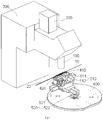
- FIG. 2 shows, on an enlarged scale, a first fixture, a second fixture, a first moving mechanism, and a second moving mechanism of the welding system of FIG. 1 ;
- FIG. 1 is a perspective view of a welding system according to an exemplary embodiment of the present invention and FIG. 2 shows a first fixture 410 , a second fixture 420 , a first moving mechanism 510 , and a second moving mechanism 520 of the welding system of FIG. 1 .
- the first elongated element 10 and the second elongated element 20 have a common center axis X and the end faces of the first elongated element 10 and the second elongated element 20 abut against each other.
- the first moving mechanism 510 has a moving platform adapted to move in a first direction X and a second direction Y perpendicular to the first direction X in a horizontal plane.
- the first moving mechanism 510 comprises a first moving platform 511 adapted to move in the first direction X and a second moving platform 512 mounted on the first moving platform 511 and adapted to move in the second direction Y.
- the first fixture 410 is mounted on the second moving platform 512 of the first moving mechanism 510 .
Landscapes
- Physics & Mathematics (AREA)
- Optics & Photonics (AREA)
- Engineering & Computer Science (AREA)
- Mechanical Engineering (AREA)
- Plasma & Fusion (AREA)
- Laser Beam Processing (AREA)
Abstract
Description
Claims (14)
Applications Claiming Priority (3)
| Application Number | Priority Date | Filing Date | Title |
|---|---|---|---|
| CN201610380325.6 | 2016-06-01 | ||
| CN201610380325.6A CN107442933A (en) | 2016-06-01 | 2016-06-01 | Welding system and welding method |
| CN201610380325 | 2016-06-01 |
Publications (2)
| Publication Number | Publication Date |
|---|---|
| US20170348800A1 US20170348800A1 (en) | 2017-12-07 |
| US10773341B2 true US10773341B2 (en) | 2020-09-15 |
Family
ID=58994850
Family Applications (1)
| Application Number | Title | Priority Date | Filing Date |
|---|---|---|---|
| US15/611,020 Active 2038-06-26 US10773341B2 (en) | 2016-06-01 | 2017-06-01 | Welding system and method |
Country Status (3)
| Country | Link |
|---|---|
| US (1) | US10773341B2 (en) |
| EP (1) | EP3257618B1 (en) |
| CN (1) | CN107442933A (en) |
Families Citing this family (5)
| Publication number | Priority date | Publication date | Assignee | Title |
|---|---|---|---|---|
| CN108500461A (en) * | 2018-05-14 | 2018-09-07 | 华南师范大学 | Filamentous metal material laser duct butt-welding method and device |
| CN108723689A (en) * | 2018-08-10 | 2018-11-02 | 隆华科技集团(洛阳)股份有限公司 | A kind of heat exchanger tube clamping method and device for heat exchanger tube butt welding |
| CN112775544A (en) * | 2019-10-22 | 2021-05-11 | 大族激光科技产业集团股份有限公司 | Workpiece welding equipment and method |
| CN116475568B (en) * | 2023-04-20 | 2026-04-03 | 华南理工大学 | A microfilament laser automatic welding device and welding method |
| CN120772418B (en) * | 2025-09-12 | 2025-12-26 | 德州市立尊焊丝有限公司 | Automatic butt joint device and butt joint method for solid welding wires |
Citations (10)
| Publication number | Priority date | Publication date | Assignee | Title |
|---|---|---|---|---|
| US3036204A (en) * | 1960-04-25 | 1962-05-22 | Seton Corp | Welding machine |
| US4049414A (en) * | 1975-07-28 | 1977-09-20 | Corning Glass Works | Method and apparatus for splicing optical fibers |
| US4153830A (en) * | 1976-10-07 | 1979-05-08 | Mitsubishi Denki Kabushiki Kaisha | Welding apparatus |
| US4626647A (en) * | 1984-07-19 | 1986-12-02 | Mitsubishi Denki Kabushiki Kaisha | Flash welding machine |
| US20040190838A1 (en) * | 2003-03-24 | 2004-09-30 | Bush Simon P. | Low profile system for joining optical fiber waveguides |
| US20050183460A1 (en) * | 2004-02-23 | 2005-08-25 | Juki Corporation | Method for joining an optical fiber and an optical lens, the apparatus for the same and an optical module |
| US7784666B2 (en) * | 2005-06-06 | 2010-08-31 | Ihi Corporation | Method and apparatus for positioning plate members to be butt-welded |
| US20110311812A1 (en) * | 2009-03-02 | 2011-12-22 | Dirk Haussmann | Method and apparatus for welding wires |
| US8653418B2 (en) * | 2010-12-29 | 2014-02-18 | Sungwoo Hitech Co., Ltd. | Device for connecting welding wire for CO2 gas welding |
| US20150343548A1 (en) * | 2014-05-30 | 2015-12-03 | GM Global Technology Operations LLC | Method for joining wire |
Family Cites Families (18)
| Publication number | Priority date | Publication date | Assignee | Title |
|---|---|---|---|---|
| JPS55151611A (en) * | 1979-05-16 | 1980-11-26 | Nippon Telegr & Teleph Corp <Ntt> | Optical fiber splicer |
| DE3320121A1 (en) * | 1983-06-03 | 1984-12-06 | Philips Patentverwaltung Gmbh, 2000 Hamburg | Device and method for fusion joining of optical fibres |
| JPS63184712A (en) * | 1986-09-26 | 1988-07-30 | Sumitomo Electric Ind Ltd | Optical fiber connection method |
| US5045668A (en) * | 1990-04-12 | 1991-09-03 | Armco Inc. | Apparatus and method for automatically aligning a welding device for butt welding workpieces |
| DE4025351A1 (en) * | 1990-08-10 | 1992-02-13 | Philips Patentverwaltung | DEVICE FOR WELDING TWO GROUPS OF LIGHT-WAVE GUIDES |
| JPH08201641A (en) * | 1995-01-23 | 1996-08-09 | Furukawa Electric Co Ltd:The | Optical fiber clamp mechanism for fusion splicer |
| JP4104769B2 (en) * | 1999-02-25 | 2008-06-18 | 株式会社フジクラ | Optical fiber fusion splicer |
| US6414262B1 (en) * | 1999-11-03 | 2002-07-02 | Nanyang Technological University | Method and apparatus for laser splicing of optical fibers |
| EP1174744A1 (en) * | 2000-07-21 | 2002-01-23 | Corning Incorporated | Method and apparatus for splicing optical fibers |
| DE10119805A1 (en) * | 2001-04-23 | 2002-10-24 | Scc Special Comm Cables Gmbh | Optical waveguide joining device for splicing optical fibers has actuator drive for displacing sliders relative to joining device |
| JP2004325990A (en) * | 2003-04-28 | 2004-11-18 | Fujikura Ltd | Fusion splicing method of different diameter optical fiber and fusion splicer |
| JP4098677B2 (en) * | 2003-06-26 | 2008-06-11 | 富士通株式会社 | Optical fiber splicer and optical fiber splicing method |
| CN2806036Y (en) * | 2005-05-25 | 2006-08-16 | 深圳市比克电池有限公司 | Laser welding assistor for cylindrical battery body |
| US20080037939A1 (en) * | 2006-07-31 | 2008-02-14 | The Hong Kong Polytechnic University | Splicing small core photonic crystal fibers and conventional single mode fiber |
| DE102010028772A1 (en) * | 2010-05-07 | 2011-11-10 | Martin Vogel | Method and device for connecting two wire ends |
| CN102873457A (en) * | 2012-10-16 | 2013-01-16 | 沈阳市东陵区(浑南新区)卓科技术开发中心 | Back face inert gas protection device for laser welding |
| WO2014125993A1 (en) * | 2013-02-14 | 2014-08-21 | 住友化学株式会社 | Cutting device, cutting method, and method of manufacturing laminate optical member |
| CN103286451B (en) * | 2013-05-29 | 2015-04-15 | 常熟理工学院 | Laser welding method for Mg-Gr-Y rare-earth magnesium alloy |
-
2016
- 2016-06-01 CN CN201610380325.6A patent/CN107442933A/en active Pending
-
2017
- 2017-05-30 EP EP17173364.5A patent/EP3257618B1/en active Active
- 2017-06-01 US US15/611,020 patent/US10773341B2/en active Active
Patent Citations (10)
| Publication number | Priority date | Publication date | Assignee | Title |
|---|---|---|---|---|
| US3036204A (en) * | 1960-04-25 | 1962-05-22 | Seton Corp | Welding machine |
| US4049414A (en) * | 1975-07-28 | 1977-09-20 | Corning Glass Works | Method and apparatus for splicing optical fibers |
| US4153830A (en) * | 1976-10-07 | 1979-05-08 | Mitsubishi Denki Kabushiki Kaisha | Welding apparatus |
| US4626647A (en) * | 1984-07-19 | 1986-12-02 | Mitsubishi Denki Kabushiki Kaisha | Flash welding machine |
| US20040190838A1 (en) * | 2003-03-24 | 2004-09-30 | Bush Simon P. | Low profile system for joining optical fiber waveguides |
| US20050183460A1 (en) * | 2004-02-23 | 2005-08-25 | Juki Corporation | Method for joining an optical fiber and an optical lens, the apparatus for the same and an optical module |
| US7784666B2 (en) * | 2005-06-06 | 2010-08-31 | Ihi Corporation | Method and apparatus for positioning plate members to be butt-welded |
| US20110311812A1 (en) * | 2009-03-02 | 2011-12-22 | Dirk Haussmann | Method and apparatus for welding wires |
| US8653418B2 (en) * | 2010-12-29 | 2014-02-18 | Sungwoo Hitech Co., Ltd. | Device for connecting welding wire for CO2 gas welding |
| US20150343548A1 (en) * | 2014-05-30 | 2015-12-03 | GM Global Technology Operations LLC | Method for joining wire |
Also Published As
| Publication number | Publication date |
|---|---|
| EP3257618B1 (en) | 2024-01-24 |
| US20170348800A1 (en) | 2017-12-07 |
| EP3257618A1 (en) | 2017-12-20 |
| CN107442933A (en) | 2017-12-08 |
Similar Documents
| Publication | Publication Date | Title |
|---|---|---|
| US10773341B2 (en) | Welding system and method | |
| CN106457468B (en) | Hybrid laser welding system and method using two robots | |
| US10005154B2 (en) | Laser processing machine | |
| US20200052451A1 (en) | Welding System | |
| BR112015024725A2 (en) | welded portion inspection apparatus and inspection method | |
| US20160236297A1 (en) | Laser welding method | |
| US10857677B2 (en) | Tip attachment to aid in programming a collaborative robot | |
| US20150336221A1 (en) | Tool for assembling components and system and method for same | |
| KR20150118312A (en) | system and method for cutting using laser | |
| ES2353628T3 (en) | PROCEDURE AND DEVICE FOR THE SETTING OF A MACHINING POSITION WITH DETERMINATION OF THE REAL MACHINING LINE IN COMPARISON WITH THE PROGRAMMED MACHINING LINE OF THE MACHINING TOOL. | |
| US9776278B2 (en) | Laser welder alignment system | |
| CN118875475A (en) | Laser welding method for narrow space | |
| JP4287494B2 (en) | Alignment fixing method and alignment fixing device | |
| US20180161922A1 (en) | Laser machining head and origin calibration method for same | |
| KR102951096B1 (en) | Welding device and temperature measuring device | |
| EP2732899B1 (en) | Apparatus and terminal, and method for soldering a copper wire on the terminal, particularly for soldering the end of the winding wire of electric coils on a bronze terminal | |
| JP7113201B1 (en) | LASER PROCESSING APPARATUS AND METHOD FOR ADJUSTING THE FOCUS POSITION OF LASER LIGHT USING THE SAME | |
| US20120189251A1 (en) | Optical module with pig-tailed fiber and method to assembly the same | |
| KR100365509B1 (en) | Apparatus for mixed type of laser welding | |
| JP5070719B2 (en) | Laser welding apparatus and laser focus position adjusting method | |
| JP6131860B2 (en) | Teaching method using laser processing robot system | |
| US11654514B2 (en) | Laser welding system | |
| JP7438013B2 (en) | Teaching support system and teaching support method using it | |
| JP2016107277A (en) | Soldering iron | |
| JP2016120534A (en) | Positioning system and welding system |
Legal Events
| Date | Code | Title | Description |
|---|---|---|---|
| AS | Assignment |
Owner name: TYCO ELECTRONICS (SHANGHAI) CO. LTD., CHINA Free format text: ASSIGNMENT OF ASSIGNORS INTEREST;ASSIGNOR:FRANCISCO-YI LU, ROBERTO;REEL/FRAME:042565/0194 Effective date: 20170526 Owner name: SHENZHEN AMI TECHNOLOGY CO., LTD, CHINA Free format text: ASSIGNMENT OF ASSIGNORS INTEREST;ASSIGNOR:FRANCISCO-YI LU, ROBERTO;REEL/FRAME:042565/0194 Effective date: 20170526 Owner name: MEASUREMENT SPECIALITIES (CHENGDU) LTD., CHINA Free format text: ASSIGNMENT OF ASSIGNORS INTEREST;ASSIGNOR:FRANCISCO-YI LU, ROBERTO;REEL/FRAME:042565/0194 Effective date: 20170526 Owner name: TE CONNECTIVITY CORPORATION, PENNSYLVANIA Free format text: ASSIGNMENT OF ASSIGNORS INTEREST;ASSIGNOR:FRANCISCO-YI LU, ROBERTO;REEL/FRAME:042565/0194 Effective date: 20170526 |
|
| STPP | Information on status: patent application and granting procedure in general |
Free format text: DOCKETED NEW CASE - READY FOR EXAMINATION |
|
| AS | Assignment |
Owner name: TE CONNECTIVITY CORPORATION, PENNSYLVANIA Free format text: ASSIGNMENT OF ASSIGNORS INTEREST;ASSIGNORS:DENG, YINGCONG;GONG, LAN;YING, QIAN;AND OTHERS;SIGNING DATES FROM 20170815 TO 20171013;REEL/FRAME:044680/0492 Owner name: MEASUREMENT SPECIALTIES (CHENGDU) LTD, CHINA Free format text: ASSIGNMENT OF ASSIGNORS INTEREST;ASSIGNORS:DENG, YINGCONG;GONG, LAN;YING, QIAN;AND OTHERS;SIGNING DATES FROM 20170815 TO 20171013;REEL/FRAME:044680/0492 Owner name: TYCO ELECTRONICS (SHANGHAI) CO. LTD., CHINA Free format text: ASSIGNMENT OF ASSIGNORS INTEREST;ASSIGNORS:DENG, YINGCONG;GONG, LAN;YING, QIAN;AND OTHERS;SIGNING DATES FROM 20170815 TO 20171013;REEL/FRAME:044680/0492 Owner name: SHENZHEN AMI TECHNOLOGY CO., LTD., CHINA Free format text: ASSIGNMENT OF ASSIGNORS INTEREST;ASSIGNORS:DENG, YINGCONG;GONG, LAN;YING, QIAN;AND OTHERS;SIGNING DATES FROM 20170815 TO 20171013;REEL/FRAME:044680/0492 |
|
| STPP | Information on status: patent application and granting procedure in general |
Free format text: NON FINAL ACTION MAILED |
|
| STPP | Information on status: patent application and granting procedure in general |
Free format text: RESPONSE TO NON-FINAL OFFICE ACTION ENTERED AND FORWARDED TO EXAMINER |
|
| STPP | Information on status: patent application and granting procedure in general |
Free format text: FINAL REJECTION MAILED |
|
| STPP | Information on status: patent application and granting procedure in general |
Free format text: RESPONSE AFTER FINAL ACTION FORWARDED TO EXAMINER |
|
| STPP | Information on status: patent application and granting procedure in general |
Free format text: NOTICE OF ALLOWANCE MAILED -- APPLICATION RECEIVED IN OFFICE OF PUBLICATIONS |
|
| STPP | Information on status: patent application and granting procedure in general |
Free format text: PUBLICATIONS -- ISSUE FEE PAYMENT VERIFIED |
|
| STCF | Information on status: patent grant |
Free format text: PATENTED CASE |
|
| AS | Assignment |
Owner name: TE CONNECTIVITY SERVICES GMBH, SWITZERLAND Free format text: ASSIGNMENT OF ASSIGNORS INTEREST;ASSIGNOR:TE CONNECTIVITY CORPORATION;REEL/FRAME:056524/0226 Effective date: 20180928 Owner name: TE CONNECTIVITY SERVICES GMBH, SWITZERLAND Free format text: CHANGE OF ADDRESS;ASSIGNOR:TE CONNECTIVITY SERVICES GMBH;REEL/FRAME:056524/0531 Effective date: 20191101 |
|
| AS | Assignment |
Owner name: TE CONNECTIVITY SOLUTIONS GMBH, SWITZERLAND Free format text: MERGER;ASSIGNOR:TE CONNECTIVITY SERVICES GMBH;REEL/FRAME:060885/0482 Effective date: 20220301 |
|
| MAFP | Maintenance fee payment |
Free format text: PAYMENT OF MAINTENANCE FEE, 4TH YEAR, LARGE ENTITY (ORIGINAL EVENT CODE: M1551); ENTITY STATUS OF PATENT OWNER: LARGE ENTITY Year of fee payment: 4 |