US10768044B2 - Optical sensor device - Google Patents
Optical sensor device Download PDFInfo
- Publication number
- US10768044B2 US10768044B2 US16/306,649 US201716306649A US10768044B2 US 10768044 B2 US10768044 B2 US 10768044B2 US 201716306649 A US201716306649 A US 201716306649A US 10768044 B2 US10768044 B2 US 10768044B2
- Authority
- US
- United States
- Prior art keywords
- optical sensor
- light
- additional
- sensor arrangement
- arrangement
- Prior art date
- Legal status (The legal status is an assumption and is not a legal conclusion. Google has not performed a legal analysis and makes no representation as to the accuracy of the status listed.)
- Active, expires
Links
- 230000003287 optical effect Effects 0.000 title claims abstract description 248
- 238000011156 evaluation Methods 0.000 claims abstract description 22
- 239000002184 metal Substances 0.000 claims abstract description 18
- 230000002596 correlated effect Effects 0.000 claims description 5
- 230000000903 blocking effect Effects 0.000 claims description 2
- 230000002238 attenuated effect Effects 0.000 description 3
- 238000005259 measurement Methods 0.000 description 2
- 230000005855 radiation Effects 0.000 description 2
- 238000004088 simulation Methods 0.000 description 2
- 238000004364 calculation method Methods 0.000 description 1
- 230000001419 dependent effect Effects 0.000 description 1
- 230000000694 effects Effects 0.000 description 1
- 238000012856 packing Methods 0.000 description 1
Images


Classifications
-
- G—PHYSICS
- G01—MEASURING; TESTING
- G01J—MEASUREMENT OF INTENSITY, VELOCITY, SPECTRAL CONTENT, POLARISATION, PHASE OR PULSE CHARACTERISTICS OF INFRARED, VISIBLE OR ULTRAVIOLET LIGHT; COLORIMETRY; RADIATION PYROMETRY
- G01J1/00—Photometry, e.g. photographic exposure meter
- G01J1/02—Details
- G01J1/0266—Field-of-view determination; Aiming or pointing of a photometer; Adjusting alignment; Encoding angular position; Size of the measurement area; Position tracking; Photodetection involving different fields of view for a single detector
-
- G—PHYSICS
- G01—MEASURING; TESTING
- G01J—MEASUREMENT OF INTENSITY, VELOCITY, SPECTRAL CONTENT, POLARISATION, PHASE OR PULSE CHARACTERISTICS OF INFRARED, VISIBLE OR ULTRAVIOLET LIGHT; COLORIMETRY; RADIATION PYROMETRY
- G01J1/00—Photometry, e.g. photographic exposure meter
- G01J1/02—Details
- G01J1/04—Optical or mechanical part supplementary adjustable parts
- G01J1/06—Restricting the angle of incident light
-
- G—PHYSICS
- G01—MEASURING; TESTING
- G01J—MEASUREMENT OF INTENSITY, VELOCITY, SPECTRAL CONTENT, POLARISATION, PHASE OR PULSE CHARACTERISTICS OF INFRARED, VISIBLE OR ULTRAVIOLET LIGHT; COLORIMETRY; RADIATION PYROMETRY
- G01J1/00—Photometry, e.g. photographic exposure meter
- G01J1/42—Photometry, e.g. photographic exposure meter using electric radiation detectors
- G01J1/4204—Photometry, e.g. photographic exposure meter using electric radiation detectors with determination of ambient light
-
- G—PHYSICS
- G01—MEASURING; TESTING
- G01J—MEASUREMENT OF INTENSITY, VELOCITY, SPECTRAL CONTENT, POLARISATION, PHASE OR PULSE CHARACTERISTICS OF INFRARED, VISIBLE OR ULTRAVIOLET LIGHT; COLORIMETRY; RADIATION PYROMETRY
- G01J1/00—Photometry, e.g. photographic exposure meter
- G01J1/42—Photometry, e.g. photographic exposure meter using electric radiation detectors
- G01J1/429—Photometry, e.g. photographic exposure meter using electric radiation detectors applied to measurement of ultraviolet light
-
- G—PHYSICS
- G01—MEASURING; TESTING
- G01S—RADIO DIRECTION-FINDING; RADIO NAVIGATION; DETERMINING DISTANCE OR VELOCITY BY USE OF RADIO WAVES; LOCATING OR PRESENCE-DETECTING BY USE OF THE REFLECTION OR RERADIATION OF RADIO WAVES; ANALOGOUS ARRANGEMENTS USING OTHER WAVES
- G01S3/00—Direction-finders for determining the direction from which infrasonic, sonic, ultrasonic, or electromagnetic waves, or particle emission, not having a directional significance, are being received
- G01S3/78—Direction-finders for determining the direction from which infrasonic, sonic, ultrasonic, or electromagnetic waves, or particle emission, not having a directional significance, are being received using electromagnetic waves other than radio waves
- G01S3/782—Systems for determining direction or deviation from predetermined direction
- G01S3/783—Systems for determining direction or deviation from predetermined direction using amplitude comparison of signals derived from static detectors or detector systems
-
- G—PHYSICS
- G01—MEASURING; TESTING
- G01S—RADIO DIRECTION-FINDING; RADIO NAVIGATION; DETERMINING DISTANCE OR VELOCITY BY USE OF RADIO WAVES; LOCATING OR PRESENCE-DETECTING BY USE OF THE REFLECTION OR RERADIATION OF RADIO WAVES; ANALOGOUS ARRANGEMENTS USING OTHER WAVES
- G01S3/00—Direction-finders for determining the direction from which infrasonic, sonic, ultrasonic, or electromagnetic waves, or particle emission, not having a directional significance, are being received
- G01S3/78—Direction-finders for determining the direction from which infrasonic, sonic, ultrasonic, or electromagnetic waves, or particle emission, not having a directional significance, are being received using electromagnetic waves other than radio waves
- G01S3/782—Systems for determining direction or deviation from predetermined direction
- G01S3/785—Systems for determining direction or deviation from predetermined direction using adjustment of orientation of directivity characteristics of a detector or detector system to give a desired condition of signal derived from that detector or detector system
- G01S3/786—Systems for determining direction or deviation from predetermined direction using adjustment of orientation of directivity characteristics of a detector or detector system to give a desired condition of signal derived from that detector or detector system the desired condition being maintained automatically
- G01S3/7861—Solar tracking systems
-
- G—PHYSICS
- G01—MEASURING; TESTING
- G01J—MEASUREMENT OF INTENSITY, VELOCITY, SPECTRAL CONTENT, POLARISATION, PHASE OR PULSE CHARACTERISTICS OF INFRARED, VISIBLE OR ULTRAVIOLET LIGHT; COLORIMETRY; RADIATION PYROMETRY
- G01J1/00—Photometry, e.g. photographic exposure meter
- G01J1/42—Photometry, e.g. photographic exposure meter using electric radiation detectors
- G01J2001/4266—Photometry, e.g. photographic exposure meter using electric radiation detectors for measuring solar light
Definitions
- the present application relates to an optical sensor device that can detect directional and non-directional light, for example ultra-violet light.
- Light reaching an optical sensor can be either direct, which means it comes directly from the light source and is not scattered, or it can be non-directional or ambient, which means that it is scattered.
- the light source can be, for example, the sun. Therefore, on a clear day with no clouds, nearly all of the light coming from the sun to the sensor is direct and not scattered. However, on a cloudy day most of the light reaching the sensor is scattered and comes from different directions. In order to measure the intensity of, for example, ultra-violet light, for different surrounding light conditions or different weather conditions it is necessary to detect light that comes from different directions.
- a known solution for detecting ultra-violet light is employing an interference filter on top of an optical sensor.
- the interference filter requires the incident light to be perpendicular towards the light-sensitive surface or nearly perpendicular to this surface.
- a diffuser with an air gap is employed. With the diffuser only light with an incidence angle close to 90° towards the light-sensitive surface is passed to the sensor.
- the present disclosure provides an optical sensor device that measures the incidence angle of incoming light that is approximately on the main beam axis of a light source and that comprises a small package height.
- the optical sensor device comprises at least two optical sensor arrangements and an evaluation circuit.
- the first optical sensor arrangement comprises at least one optical sensor structure which can measure the incidence angle of incoming light that is approximately on the main beam axis of a light source.
- the light source can be, for example, the sun.
- Light that is approximately on the main beam axis of the light source is direct light and light that is not on the main beam axis of the light source is scattered or ambient light.
- the second optical sensor arrangement comprises at least one optical sensor structure with at least one optical sensor with a light-sensitive surface.
- An aperture is formed above the optical sensor by a layer structure including at least two metal layers where one of the layers is in the plane of the optical sensor and the other one is stacked further above.
- Opaque walls may connect the layers to help optically isolate the optical sensor.
- the field of view of the optical sensor is limited to for example 15°.
- no diffuser is required to limit the range of incidence angles of incoming light. Therefore, direct (unscattered) light is not attenuated before it reaches the optical sensor. Also, without a diffuser and an air gap, a small package height can be realized.
- the evaluation circuit is connected to an output of the first optical sensor arrangement and to an output of the second optical sensor arrangement.
- the evaluation circuit provides the output signal of the second optical sensor arrangement under the condition that the incidence angle measured by the first optical sensor arrangement lies within a set interval.
- the evaluation circuit In order to detect direct light with the second optical sensor arrangement it is necessary to orient the light-sensitive surface of the optical sensor perpendicular towards the direct incoming light. Therefore, the evaluation circuit only provides the output signal of the second optical sensor arrangement if the incidence angle of the incoming light is 90° or close to 90° towards the light-sensitive surface.
- the orientation of the optical sensor device can be adjusted in such a way that the incidence angle of the incoming light lies within the set interval so that the evaluation circuit provides the output signal of the second optical sensor arrangement.
- the incidence angle of direct incoming light is measured by directional sensor structures.
- the first optical sensor arrangement comprises at least two further optical sensor structures.
- the at least three optical sensor structures are directional and detect light incident from at least three different directions.
- the first optical sensor arrangement comprises at least four directional optical sensor structures.
- the incidence angle of direct light it is possible to adjust the orientation of the optical sensor device in such a way that the incidence angle is 90° or close to 90°.
- the four different directions are referred to as N for north, S for south, E for east and W for west.
- the incidence angle ⁇ of the direct light towards the normal of the light-sensitive surface is estimated by: ⁇ square root over ( ⁇ NS 2 + ⁇ EW 2 ) ⁇ ,
- ⁇ NS is the incidence angle of the direct light projected in the plane of the two directions N and S
- ⁇ EW is the incidence angle of the direct light projected in the plane of the two directions E and W.
- the angle ⁇ is also referred to as the zenith.
- N,S,E and W are the intensities measured by the respective directional sensors and a tan is the four-quadrant arctangent which returns an angle between ⁇ and ⁇ .
- the at least one optical sensor structure in the first optical sensor arrangement comprises at least one optical sensor with a light-sensitive surface.
- An aperture is formed above the optical sensor by a layer structure including at least two metal layers where one of the layers is in the plane of the optical sensor and the other one is stacked further above.
- Opaque walls connect the layers and they optically isolate the optical sensor. This means that if the incidence angle of the direct light is 90° or close to 90° nearly only direct light is detected by the optical sensor. In this situation the at least three directional optical sensor structures detect ambient light from different directions.
- the evaluation circuit displays a ratio of the signal detected by the at least three directional optical sensor structures in the first optical sensor arrangement to the signal detected by the at least one optical sensor structure in the first optical sensor arrangement which detects the direct light. This ratio is referred to as the haze index.
- the haze index HI is calculated as follows:
- k is a constant of proportionality and H is the intensity measured by the optical sensor structure detecting direct light.
- the constant k is chosen in such a way that the haze index is normalized between 0 and 1.
- the haze index gives a ratio of ambient versus direct light. For outside conditions this means that the haze index is a measure for the cloudiness of the respective weather situation.
- the optical sensor device comprises one further optical sensor structure in the first optical sensor arrangement.
- This further optical sensor structure comprises at least one optical sensor with a light-sensitive surface.
- An aperture is formed above the optical sensor by a layer structure including at least two metal layers where one of the layers is in the plane of the optical sensor and the other one is stacked further above.
- Opaque walls may connect the layers to help optically isolate the optical sensor.
- Another opaque layer blocks light that is incident perpendicular towards the light-sensitive surface.
- this further optical sensor structure detects scattered light which is coming from different directions.
- the haze index can be determined by the ratio of the output signals from this optical sensor structure and from the optical sensor structure which detects direct light.
- An advantage of this embodiment is that only two optical sensor structures are required to determine the haze index. This means that only two analogue-digital channels are required instead of five.
- these two optical sensor structures required to determine the haze index detect light in the visible range.
- Their sensor area is small so that they can be operated outside without suffering from saturation in direct sunlight.
- the evaluation circuit provides the output signal of the second optical sensor arrangement under the condition that the output signal of the optical sensor structure detecting the direct light reaches a maximum value and that the output signal of the optical sensor structure detecting the scattered light reaches a minimum value. This means that the incidence angle of the incoming light does not have to be measured, but by comparing the signals of these two optical sensor structures it can be determined under which conditions the optical sensor device is oriented perpendicular to the direct light or close to perpendicular.
- the intensity is assumed to be 1 Watt per steradian and it is integrated over a sphere with the radius 1.
- the irradiance on a fully exposed surface is n.
- the fraction detected by a directional sensor with an opening angle ⁇ amounts to sin 2 ⁇ .
- UV estimated UV measured sin 2 ⁇ ⁇ ,
- UV measured is the measured intensity
- the total intensity of the ultra-violet light can also be estimated for different haze indices. This means that the intensity of the ultra-violet light can be estimated for different weather situations.
- the haze index being a value between 0 and 1
- f is a weakly non-linear and monotonically increasing function of the haze index HI
- k a and k d are constants.
- the optical sensor structures in the first optical sensor arrangement which measure direct and the ones that measure ambient light contain color filters above their apertures. By employing these color filters the color correlated temperature can be determined.
- the area of the sensor without a color filter is smaller than the total area of the sensors with color filters.
- the sensor without the color filter receives more radiation than the ones with the color filters, so it saturates before the color filter sensors.
- the dynamic range of the color sensor is increased since the sensor area of the sensor without a color filter is smaller than the area of the sensors with a color filter.
- only one color filter is employed per optical sensor so that an angle-dependent color breakup is avoided.
- the evaluation circuit provides the output signal of the second optical sensor arrangement under the condition that the measured color correlated temperature is within a set range.
- the color correlated temperature is also a measure for the haziness. Therefore, certain temperatures can be defined so that the output signal of the second optical sensor arrangement is only provided for certain weather conditions.
- the measured incidence angle of the incoming light is displayed by the evaluation circuit. This allows to adjust the orientation of the optical sensor device in such a way that the direct light is perpendicular towards the light-sensitive surfaces.
- the range for valid values of the output signal of the first optical sensor arrangement can be set. With this, the required accuracy of the alignment of the optical sensor device towards the direct incident light can be set.
- the optical sensor structures in the first and/or the second optical sensor arrangement are shaped hexagonally and they are arranged in a honeycomb structure. This arrangement allows a close packing of the optical sensor structures. If the optical sensor device is operated only outside, the sensor structures can be small since the intensity of the outside light is very high. If the optical sensor device is operated inside the sensor structure area is larger to enable sensing small intensities.
- At least one optical sensor structure in the first optical sensor arrangement is covered with an infrared-blocking filter.
- the first optical sensor arrangement detects light in the visible range.
- these sensors can be very small since the visible outside light is very intense. It is also desired to determine the haze index from light in the visible range because the scattering of ultraviolet and infrared light can be very different. However, the scattering of ultra-violet light is expected to correlate better with visible light.
- the second optical sensor arrangement detects ultra-violet light and therefore at least one optical sensor structure in the second optical sensor arrangement is covered with an ultra-violet pass filter. This embodiment is preferred since the objective of the application is to detect ultra-violet light under different surrounding light conditions.
- FIG. 1 shows an exemplary embodiment of the optical sensor device
- FIGS. 2A and 2B show the incidence of direct and ambient sunlight onto the detector aperture
- FIGS. 3A to 3C show the setup of examples of different optical sensor structures
- FIG. 4 shows an exemplary embodiment of an optical sensor arrangement that measures the haze index including three directional sensors
- FIG. 5 shows the angular field of view of four directional sensors and one sensor that detects direct light
- FIG. 6 shows experimental results of an exemplary embodiment that measures the incidence angle
- FIG. 7A shows the setup of an exemplary embodiment providing the haze index
- FIG. 7B shows simulation results for an exemplary embodiment providing the haze index
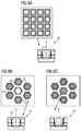
- FIG. 8A to 8C show exemplary embodiments with color filters and arrangements of the optical sensor structures.
- FIGS. 9A and 9B show exemplary embodiments with four and eight directional optical sensor structures, respectively.
- FIG. 1 shows an embodiment of an optical sensor device 1 that detects directional and non-directional light.
- a first optical sensor arrangement 10 includes at least one optical sensor structure 11 .
- the first optical sensor arrangement 10 detects incident light 12 .
- An output 13 of the first optical sensor arrangement 10 is connected to an evaluation circuit 14 .
- a second optical sensor arrangement 15 includes at least one optical sensor structure 16 .
- the second optical sensor arrangement 15 detects incident light 12 .
- the second optical sensor arrangement 15 has an output 17 which is connected to the evaluation circuit 14 and provides an output signal 46 .
- the evaluation circuit 14 has at least two outputs 18 and 19 .
- the output 18 provides the output signal 46 of the second optical sensor arrangement 15 .
- the first optical sensor arrangement 10 measures the incidence angle ⁇ of incoming light 12 that is approximately on the main beam axis 20 of a light source 22 .
- the output 19 of the evaluation circuit 14 provides the incidence angle ⁇ measured by the first optical sensor arrangement 10 .
- a range for allowed values of the incidence angle ⁇ is set.
- the evaluation circuit 14 provides the output signal 46 of the second optical sensor arrangement 15 under the condition that the measured incidence angle ⁇ is within the set range.
- the output 19 of the evaluation circuit 14 provides the measured incidence angle ⁇ so that the orientation of the optical sensor device 1 can be changed in such a way that the measured incidence angle ⁇ is within the given range.
- FIGS. 2A and 2B show the optical sensor device 1 and a light source 22 which, for example, can be the sun, as shown in this case.
- FIG. 2A shows the case of a clear day. Most of the sunlight is not scattered and reaches a detector aperture 23 directly. At the detector aperture 23 the angular spread of direct sunlight 34 amounts to 0.5°. Under these weather conditions only about 10% of the solar radiation is scattered. Scattered or ambient light 35 reaches the detector aperture 23 from different angles.
- FIG. 2B shows the case of a cloudy or overcast day. Almost no direct light 34 reaches the detector aperture 23 . Most of the light that reaches the detector aperture is scattered.
- FIG. 3A shows an exemplary embodiment of the optical sensor structure 16 of the second optical sensor arrangement 15 .
- the optical sensor structure 16 comprises an optical sensor 24 , at least two metal layers 43 and 44 and an aperture 25 .
- the optical sensor structure 16 comprises three metal layers 43 , 44 and 45 .
- Vias or other connectors 26 may connect the metal layers and optically isolate the optical sensor 24 .
- the aperture 25 defines an angular field of view of the optical sensor 24 with an opening angle of ⁇ .
- the optical sensor 24 is an ultra-violet light sensor.
- FIG. 3B shows one embodiment of the optical sensor structure 11 of the first optical sensor arrangement 10 .
- the setup is the same as for the optical sensor structure 16 of the second optical sensor arrangement 15 .
- the optical sensor 24 in the optical sensor structure 11 is covered with an infrared blocking filter.
- FIG. 3C shows one embodiment of a second optical sensor structure 27 in the first optical sensor arrangement 10 . It also comprises the same setup as the optical sensor structure 16 with the only difference that in the plane of the topmost metal layer 44 there is another metal layer 28 that blocks light that is incident perpendicular towards the optical sensor 24 . With this, light incident from directions that are not perpendicular towards the optical sensor 24 are detected.
- the optical sensor 24 in the optical sensor structure 27 is covered with an infrared filter.
- FIG. 4 shows one embodiment of the optical sensor arrangement 10 that measures the incidence angle of direct incident light towards the normal of the optical sensor 24 .
- Three directional sensors 29 , 30 and 31 detect light that is incident from different directions but not perpendicular towards the optical sensors.
- the optical sensor structure 11 detects light that is incident perpendicular towards its light-sensitive surface 32 . With this arrangement the incidence angle ⁇ of direct light can be determined.
- FIG. 5 shows angular fields of view 37 , 38 , 39 and 40 for four different directional sensors.
- the four directional sensors are referred to as north, south, east and west and they detect incoming light from four different directions.
- the angular field of view 36 of a sensor detecting the direct light is shown, which is defined by the opening angle ⁇ of an optical sensor.
- FIG. 6 shows experimental results for an optical sensor device including two directional sensors referred to as N and S.
- the incidence angle ⁇ NS is plotted over the ratio N ⁇ S/N+S of the signals of the two directional sensors. In a range of +/ ⁇ 20° the ratio shows a linear shape.
- the dotted line represents the fitted function y.
- the offset of ⁇ 1.5° is due to a measurement artefact. With this it is shown that within a certain range the incidence angle ⁇ NS of the incident light can be determined.
- FIG. 7A shows a haze detector employing two optical sensor structures.
- One optical sensor structure 11 has an aperture 25 such that light is detected which is incident perpendicular towards the light-sensitive surface 32 of the optical sensor 24 .
- the second optical sensor structure 27 detects ambient light incident from different directions.
- both optical sensor structures are shaped hexagonally.
- FIG. 7B shows simulation results for the haze detector depicted in FIG. 7A .
- different ratios of simulated ambient/direct light power are plotted over the ratio of the signals of the optical sensor structure 27 that detects ambient light and the optical sensor structure 11 that detects direct light on the x-axis. This means that for different light conditions the signal of the haze detector is detected which means the ratio of ambient light towards direct light is measured.
- the dotted line is a logarithmic fit to the simulated data. Therefore, with the haze index detected by the haze detector the ratio of ambient towards direct light can be estimated.
- FIG. 8A shows the optical sensor structure 16 which detects preferably ultra-violet light. According to one embodiment several of these optical sensor structures 16 are arranged in a square lattice where the optical sensor structures are square-shaped. An alternative embodiment is to arrange the optical sensor structures 16 in a honeycomb structure where the optical sensor structures are shaped hexagonally.
- FIG. 8B shows an optical sensor structure 11 .
- a color filter 33 is arranged on top of the aperture 25 .
- the color-correlated temperature can be determined.
- the optical sensor structure 11 is shaped hexagonally and several optical sensor structures 11 are arranged in a honeycomb structure array.
- six optical sensor structures 41 in this array comprise color filters on top of the aperture 25 and one optical sensor structure 42 does not comprise any color filter on top of its aperture. With this, the area of the optical sensor structure 42 without a color filter is smaller than the areas of the optical sensor structures 41 with a color filter such that a saturation of the optical sensor structure 41 is prevented because its area is smaller.
- FIG. 8C shows the same setup as in FIG. 8B for an optical sensor structure 27 of the first optical sensor arrangement 10 .
- the color-correlated temperature can also be determined from ambient light.
- FIG. 9A shows a preferred embodiment of the first optical sensor structure 10 .
- Four directional sensor structures 29 , 30 , 31 and 46 detect ambient light from four different directions.
- One optical sensor structure 11 detects light that is perpendicular towards the light-sensitive surface 32 of the optical sensor 24 . With this optical sensor arrangement the incidence angle ⁇ of direct incident light can be determined and also the haze index.
- FIG. 9B shows another embodiment of the optical sensor arrangement depicted in FIG. 9A where, instead of four directional sensors, eight directional sensors 29 are employed and detect ambient light incident from eight different directions.
Abstract
Description
θ≅√{square root over (θNS 2+θEW 2)},
I=2π∫0 αsin β cos βdβ=π(sin α)2,
UVestimated=UVmeasured·(k a f(HI)+k d(1−f(HI)),
Claims (13)
Priority Applications (1)
| Application Number | Priority Date | Filing Date | Title |
|---|---|---|---|
| US16/306,649 US10768044B2 (en) | 2016-06-06 | 2017-05-31 | Optical sensor device |
Applications Claiming Priority (6)
| Application Number | Priority Date | Filing Date | Title |
|---|---|---|---|
| US201662346103P | 2016-06-06 | 2016-06-06 | |
| EP16176932.8 | 2016-06-29 | ||
| EP16176932 | 2016-06-29 | ||
| EP16176932.8A EP3255397B1 (en) | 2016-06-06 | 2016-06-29 | Optical sensor device |
| PCT/EP2017/063202 WO2017211648A1 (en) | 2016-06-06 | 2017-05-31 | Optical sensor device |
| US16/306,649 US10768044B2 (en) | 2016-06-06 | 2017-05-31 | Optical sensor device |
Publications (2)
| Publication Number | Publication Date |
|---|---|
| US20190154498A1 US20190154498A1 (en) | 2019-05-23 |
| US10768044B2 true US10768044B2 (en) | 2020-09-08 |
Family
ID=56368817
Family Applications (1)
| Application Number | Title | Priority Date | Filing Date |
|---|---|---|---|
| US16/306,649 Active 2037-06-22 US10768044B2 (en) | 2016-06-06 | 2017-05-31 | Optical sensor device |
Country Status (3)
| Country | Link |
|---|---|
| US (1) | US10768044B2 (en) |
| EP (1) | EP3255397B1 (en) |
| WO (1) | WO2017211648A1 (en) |
Families Citing this family (3)
| Publication number | Priority date | Publication date | Assignee | Title |
|---|---|---|---|---|
| EP3571480A4 (en) * | 2017-01-17 | 2021-02-24 | Micasense, Inc. | Multi-sensor irradiance estimation |
| EP3644365A1 (en) * | 2018-10-25 | 2020-04-29 | ams International AG | Optical sensor device and method for manufacturing an optical sensor device |
| CN111968600B (en) * | 2020-08-28 | 2022-03-25 | Oppo广东移动通信有限公司 | Display device, electronic apparatus, and control method of electronic apparatus |
Citations (7)
| Publication number | Priority date | Publication date | Assignee | Title |
|---|---|---|---|---|
| JP2003021688A (en) | 2001-07-06 | 2003-01-24 | Honda Motor Co Ltd | Solar radiation sensor |
| JP2003130727A (en) | 2001-10-22 | 2003-05-08 | Canon Inc | Apparatus and method for measuring intensity of light, photodetector and data processor |
| US20090230313A1 (en) | 2008-03-17 | 2009-09-17 | Oki Semiconductor Co., Ltd. | Light quantity measuring device and method for measuring light quantity |
| EP2873953A1 (en) | 2013-11-13 | 2015-05-20 | ams AG | Light sensor arrangement and spectrometer |
| US20160041035A1 (en) * | 2014-08-05 | 2016-02-11 | Maxim Integrated Products, Inc. | System and method of estimating spectral contributions in ambient light and correcting field of view errors |
| US20160309564A1 (en) * | 2015-04-16 | 2016-10-20 | Apple Inc. | Electronic Device With Directional Ambient Light Sensor |
| US20190080668A1 (en) * | 2017-09-08 | 2019-03-14 | Apple Inc. | Electronic Devices With Ambient Light Sensors |
-
2016
- 2016-06-29 EP EP16176932.8A patent/EP3255397B1/en active Active
-
2017
- 2017-05-31 WO PCT/EP2017/063202 patent/WO2017211648A1/en active Application Filing
- 2017-05-31 US US16/306,649 patent/US10768044B2/en active Active
Patent Citations (7)
| Publication number | Priority date | Publication date | Assignee | Title |
|---|---|---|---|---|
| JP2003021688A (en) | 2001-07-06 | 2003-01-24 | Honda Motor Co Ltd | Solar radiation sensor |
| JP2003130727A (en) | 2001-10-22 | 2003-05-08 | Canon Inc | Apparatus and method for measuring intensity of light, photodetector and data processor |
| US20090230313A1 (en) | 2008-03-17 | 2009-09-17 | Oki Semiconductor Co., Ltd. | Light quantity measuring device and method for measuring light quantity |
| EP2873953A1 (en) | 2013-11-13 | 2015-05-20 | ams AG | Light sensor arrangement and spectrometer |
| US20160041035A1 (en) * | 2014-08-05 | 2016-02-11 | Maxim Integrated Products, Inc. | System and method of estimating spectral contributions in ambient light and correcting field of view errors |
| US20160309564A1 (en) * | 2015-04-16 | 2016-10-20 | Apple Inc. | Electronic Device With Directional Ambient Light Sensor |
| US20190080668A1 (en) * | 2017-09-08 | 2019-03-14 | Apple Inc. | Electronic Devices With Ambient Light Sensors |
Non-Patent Citations (1)
| Title |
|---|
| European Patent Office, International Search Report, PCT/EP2017/063202, dated Sep. 28, 2017. |
Also Published As
| Publication number | Publication date |
|---|---|
| EP3255397B1 (en) | 2023-02-22 |
| WO2017211648A1 (en) | 2017-12-14 |
| EP3255397A1 (en) | 2017-12-13 |
| US20190154498A1 (en) | 2019-05-23 |
Similar Documents
| Publication | Publication Date | Title |
|---|---|---|
| US11921206B2 (en) | Limitation of noise on light detectors using an aperture | |
| US10768044B2 (en) | Optical sensor device | |
| KR101000267B1 (en) | Apparatus for sensor for tracking sunlight | |
| CN105444881B (en) | Self-correcting atmosphere-earth surface optical radiation characteristic observation instrument | |
| CN101910808A (en) | Light sensor with intensity and direction detection | |
| JPH02236108A (en) | Solar sensor | |
| US20180081022A1 (en) | Sensor arrangement and method for operating a sensor arrangement | |
| CN105334027B (en) | The multispectral integrated target of high accuracy of LED illumination and supporting optical detecting method | |
| US20170248472A1 (en) | Determining spectral emission characteristics of incident radiation | |
| US20160299008A1 (en) | Light sensor arrangement and spectrometer | |
| TW201205050A (en) | Optical system for measurements, and luminance colorimeter and colorimeter using same | |
| Hanselaer et al. | A new integrating sphere design for spectral radiant flux determination of light-emitting diodes | |
| EP3404379B1 (en) | Optical device for angle measurements | |
| CN104634765B (en) | The apparatus and method that atmospheric transmittance is measured based on optical radiation measuring instrument | |
| CN113219502B (en) | Remote sensor on-satellite calibration equipment, calibration system and calibration method | |
| CN207515908U (en) | A kind of multi-pass self calibration polarization detecting device and system | |
| US5332904A (en) | Broadband radiometer | |
| US20170201657A1 (en) | Bandpass filter with variable passband | |
| Mueller et al. | Characterization of oceanographic and atmospheric radiometers | |
| US20190331526A1 (en) | A Photometric Test System for Light Emitting Devices | |
| TWI804255B (en) | A polyhedron light sensing device | |
| JPWO2015151233A1 (en) | Spectrometer and integrating sphere | |
| Hallberg et al. | Round robin comparison of BRDF measurements | |
| CN203083699U (en) | Ultraviolet light source light equalizing device | |
| RU2515132C2 (en) | Calibrated device for measurement of sensitivity and threshold energy of photodetector devices with optical system |
Legal Events
| Date | Code | Title | Description |
|---|---|---|---|
| FEPP | Fee payment procedure |
Free format text: ENTITY STATUS SET TO UNDISCOUNTED (ORIGINAL EVENT CODE: BIG.); ENTITY STATUS OF PATENT OWNER: LARGE ENTITY |
|
| AS | Assignment |
Owner name: AMS INTERNATIONAL AG, SWITZERLAND Free format text: ASSIGNMENT OF ASSIGNORS INTEREST;ASSIGNORS:MEHRL, DAVID;CHESLER, TROY;DIERSCHKE, EUGENE G.;SIGNING DATES FROM 20190109 TO 20190118;REEL/FRAME:048263/0980 |
|
| STPP | Information on status: patent application and granting procedure in general |
Free format text: DOCKETED NEW CASE - READY FOR EXAMINATION |
|
| STPP | Information on status: patent application and granting procedure in general |
Free format text: NON FINAL ACTION MAILED |
|
| STPP | Information on status: patent application and granting procedure in general |
Free format text: RESPONSE TO NON-FINAL OFFICE ACTION ENTERED AND FORWARDED TO EXAMINER |
|
| STCF | Information on status: patent grant |
Free format text: PATENTED CASE |
|
| MAFP | Maintenance fee payment |
Free format text: PAYMENT OF MAINTENANCE FEE, 4TH YEAR, LARGE ENTITY (ORIGINAL EVENT CODE: M1551); ENTITY STATUS OF PATENT OWNER: LARGE ENTITY Year of fee payment: 4 |