US10761456B2 - Developing device and image forming apparatus - Google Patents
Developing device and image forming apparatus Download PDFInfo
- Publication number
- US10761456B2 US10761456B2 US16/382,510 US201916382510A US10761456B2 US 10761456 B2 US10761456 B2 US 10761456B2 US 201916382510 A US201916382510 A US 201916382510A US 10761456 B2 US10761456 B2 US 10761456B2
- Authority
- US
- United States
- Prior art keywords
- developing device
- paddle
- toner
- screw
- discontinuous region
- Prior art date
- Legal status (The legal status is an assumption and is not a legal conclusion. Google has not performed a legal analysis and makes no representation as to the accuracy of the status listed.)
- Active
Links
- 238000011144 upstream manufacturing Methods 0.000 claims abstract description 12
- 238000001514 detection method Methods 0.000 claims description 56
- 108091008695 photoreceptors Proteins 0.000 claims description 18
- 239000007788 liquid Substances 0.000 claims description 7
- 238000003756 stirring Methods 0.000 description 35
- 238000010586 diagram Methods 0.000 description 24
- 244000126211 Hericium coralloides Species 0.000 description 3
- 230000009471 action Effects 0.000 description 3
- 239000003086 colorant Substances 0.000 description 3
- 238000009825 accumulation Methods 0.000 description 1
- 239000003990 capacitor Substances 0.000 description 1
- 238000004140 cleaning Methods 0.000 description 1
- 238000004891 communication Methods 0.000 description 1
- 238000010438 heat treatment Methods 0.000 description 1
- 239000004973 liquid crystal related substance Substances 0.000 description 1
- 238000000034 method Methods 0.000 description 1
- 230000002093 peripheral effect Effects 0.000 description 1
- 230000035699 permeability Effects 0.000 description 1
- 230000008569 process Effects 0.000 description 1
- 230000007704 transition Effects 0.000 description 1
Images


Classifications
-
- G—PHYSICS
- G03—PHOTOGRAPHY; CINEMATOGRAPHY; ANALOGOUS TECHNIQUES USING WAVES OTHER THAN OPTICAL WAVES; ELECTROGRAPHY; HOLOGRAPHY
- G03G—ELECTROGRAPHY; ELECTROPHOTOGRAPHY; MAGNETOGRAPHY
- G03G15/00—Apparatus for electrographic processes using a charge pattern
- G03G15/06—Apparatus for electrographic processes using a charge pattern for developing
- G03G15/08—Apparatus for electrographic processes using a charge pattern for developing using a solid developer, e.g. powder developer
- G03G15/0822—Arrangements for preparing, mixing, supplying or dispensing developer
- G03G15/0887—Arrangements for conveying and conditioning developer in the developing unit, e.g. agitating, removing impurities or humidity
- G03G15/0891—Arrangements for conveying and conditioning developer in the developing unit, e.g. agitating, removing impurities or humidity for conveying or circulating developer, e.g. augers
- G03G15/0893—Arrangements for conveying and conditioning developer in the developing unit, e.g. agitating, removing impurities or humidity for conveying or circulating developer, e.g. augers in a closed loop within the sump of the developing device
-
- G—PHYSICS
- G03—PHOTOGRAPHY; CINEMATOGRAPHY; ANALOGOUS TECHNIQUES USING WAVES OTHER THAN OPTICAL WAVES; ELECTROGRAPHY; HOLOGRAPHY
- G03G—ELECTROGRAPHY; ELECTROPHOTOGRAPHY; MAGNETOGRAPHY
- G03G15/00—Apparatus for electrographic processes using a charge pattern
- G03G15/06—Apparatus for electrographic processes using a charge pattern for developing
- G03G15/08—Apparatus for electrographic processes using a charge pattern for developing using a solid developer, e.g. powder developer
- G03G15/0822—Arrangements for preparing, mixing, supplying or dispensing developer
- G03G15/0887—Arrangements for conveying and conditioning developer in the developing unit, e.g. agitating, removing impurities or humidity
- G03G15/0889—Arrangements for conveying and conditioning developer in the developing unit, e.g. agitating, removing impurities or humidity for agitation or stirring
-
- G—PHYSICS
- G03—PHOTOGRAPHY; CINEMATOGRAPHY; ANALOGOUS TECHNIQUES USING WAVES OTHER THAN OPTICAL WAVES; ELECTROGRAPHY; HOLOGRAPHY
- G03G—ELECTROGRAPHY; ELECTROPHOTOGRAPHY; MAGNETOGRAPHY
- G03G15/00—Apparatus for electrographic processes using a charge pattern
- G03G15/06—Apparatus for electrographic processes using a charge pattern for developing
- G03G15/08—Apparatus for electrographic processes using a charge pattern for developing using a solid developer, e.g. powder developer
- G03G15/0822—Arrangements for preparing, mixing, supplying or dispensing developer
- G03G15/0887—Arrangements for conveying and conditioning developer in the developing unit, e.g. agitating, removing impurities or humidity
- G03G15/0891—Arrangements for conveying and conditioning developer in the developing unit, e.g. agitating, removing impurities or humidity for conveying or circulating developer, e.g. augers
Definitions
- a developing device and an image forming apparatus of the present disclosure relate to a developing device and an image forming apparatus in which an image is formed by electrophotography.
- the image forming apparatus includes an electrophotographic apparatus such as a digital copying machine, a facsimile machine, or a printer, a recording apparatus, a display device, and the like regardless of color or monochrome.
- JP 2010-210697 A relates to a developing device and an image forming apparatus, and discloses a structure of the developing device capable of reducing a difference in bulk density on a detection surface of a toner density detection sensor during stirring operation while preventing erroneous detection caused by accumulation of developer on the detection surface.
- a detection surface stirring member capable of stirring developer while rubbing a detection surface of a toner density detection sensor is provided at a position located in an axial direction of a conveyance screw and facing the detection surface in order to stabilize detection by a toner density detection sensor.
- This detection surface stirring member is formed in a rectangular waveform and includes, at each protrusion of the waveform, an elastic sheet that is flexible and deformable while contacting the detection surface.
- the toner density detection sensor is fixed to the outside of a developing device, and reads toner density of the developer inside the developing device by using a non-contact type toner density detection sensor for the developer.
- the toner density detection sensor is made by combining a coil and a capacitor, and reads magnetic permeability of a carrier inside the developer. To accurately detect the toner density inside the developing device, an amount of the developer existing at the position of the toner density detection sensor is required to be constant all the time.
- the present disclosure may be directed to: solving one or more of the above-described problems; and providing a developing device and an image forming apparatus both including a structure in which toner density of a developer inside the developing device may be accurately detected.
- FIG. 1 is a diagram illustrating a schematic structure of an image forming apparatus according to an embodiment
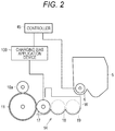
- FIG. 2 is a diagram illustrating a schematic structure of a developing device of the embodiment
- FIG. 3 is a schematic diagram to describe a circulation time in the developing device of the embodiment
- FIG. 4 is a partially enlarged perspective view illustrating a specific structure of a stirring screw of the embodiment
- FIG. 5 is a diagram illustrating an arrangement ration between a developing roller, a supply screw, and the stirring screw of the embodiment
- FIG. 6 is a schematic diagram illustrating an arrangement relation between the stirring screw, a wall surface, and a toner density detection sensor of the embodiment
- FIG. 7 is a schematic diagram illustrating a relation between a paddle and a liquid level height of developer of toner of the embodiment
- FIG. 8 is a diagram illustrating a stirring state of the developer by the paddle in a discontinuous region of the embodiment
- FIG. 9 is a schematic diagram in a case where a space between a screw blade and the paddle of the embodiment is larger on an upstream side;
- FIG. 10 is a schematic diagram in a case where a space between the screw blade and the paddle of the embodiment is larger on a downstream side;
- FIG. 11 is a diagram illustrating another form of the paddle of the embodiment.
- FIG. 12 is a schematic diagram in a case where one paddle is provided in the discontinuous region of the embodiment.
- FIG. 13 is a schematic diagram in a case where two paddles are provided in the discontinuous region of the embodiment.
- the image forming apparatus includes: an MFP having a scanner function, a copying function, a function as a printer, a facsimile function, a data communication function, and a server function; a facsimile machine; or a copying machine.
- FIG. 1 is a diagram illustrating a schematic structure of the image forming apparatus 1 according to the present embodiment.
- the image forming apparatus 1 forms an image on a recording medium by a known electrophotographic system.
- the image forming apparatus 1 includes an image processor 10 , a transfer part 20 , a sheet feeder 30 , a fixing device 40 , and a controller 45 .
- the image forming apparatus 1 selectively executes color and monochrome printing based on a print job received from an external terminal device (not illustrated) via a network (such as a LAN).
- the image processor 10 includes image forming units 10 Y, 10 M, 10 C, and 10 K corresponding to developing colors of yellow (Y), magenta (M), cyan (C), and black (K).
- the image forming unit 10 Y includes: a photoreceptor drum 11 that is an electrostatic latent image carrier; an electric charger 12 ; an exposure device 13 ; a developing device 14 ; a primary transfer roller 15 ; a cleaner 16 ; and the like which are arranged around the photoreceptor drum 11 .
- the electric charger 12 charges a peripheral surface of the photoreceptor drum 11 that is rotated in a direction indicated by an arrow A.
- the exposure device 13 exposes and scans the charged photoreceptor drum 11 with laser light to form an electrostatic latent image on the photoreceptor drum 11 .
- the developing device 14 stores developer containing toner inside thereof and develops the electrostatic latent image on the photoreceptor drum 11 with the toner, thereby forming a toner image Y on the photoreceptor drum 11 .
- the toner image is carried on the electrostatic latent image carrier.
- the primary transfer roller 15 transfers, onto the intermediate transfer body 21 , the Y color toner image that has been formed on the photoreceptor drum 11 by electrostatic action. In other words, the toner image is primarily transferred to the intermediate transfer body.
- the cleaner 16 cleans residual toner remaining on the photoreceptor drum 11 after the transfer.
- Other image forming units 10 M, 10 C, and 10 K also have structures similar to the structure of the image forming unit 10 Y, and the reference signs therein are omitted in the drawing.
- the transfer part 20 includes the intermediate transfer body 21 which is stretched around a drive roller 24 and a driven roller 25 and circulated in a direction indicated by an arrow.
- an image of toner of a corresponding color is formed on the photoreceptor drum 11 in each of the image forming units 10 M, 10 C, and 10 K, and each of the formed toner images is transferred onto the intermediate transfer body 21 .
- Image forming operation of each of the colors Y to K is executed by deviating timing sequentially from an upstream side to a downstream side such that the toner images of the respective colors are superimposed and transferred onto the same position of the intermediate transfer body 21 that is traveling.
- the sheet feeder 30 feeds sheets S that are recording media one by one from a sheet feeding cassette in accordance with the above-described image forming timing, and conveys the fed sheet S to a secondary transfer roller 22 on a conveyance path 31 .
- the sheet S conveyed to the secondary transfer roller 22 passes between the secondary transfer roller 22 and the intermediate transfer body 21 , the respective color toner images that have been formed on the intermediate transfer body 21 are collectively secondarily transferred to the sheet S by electrostatic action of the secondary transfer roller 22 . In other words, the toner image is secondarily transferred from the intermediate transfer body to the recording medium.
- the sheet S onto which the respective color toner images have been secondarily transferred is conveyed to the fixing device 40 and subjected to heating and pressing in the fixing device 40 . Consequently, the toner on the surface is fused and fixed to a surface of the sheet S, and then the sheet S is ejected onto a sheet ejection tray 33 by a sheet ejection roller 32 . Thus, an image corresponding to the toner image is formed on the recording medium.
- the toner and a toner pattern on the intermediate transfer body 21 which has not been transferred to the sheet S, are removed by a cleaning blade 26 arranged at a position facing the driven roller 25 interposing the intermediate transfer body 21 .
- a density detection sensor 23 including a reflection photoelectric sensor is arranged to detect density of a toner pattern formed on the intermediate transfer body 21 .
- the controller 45 controls the respective components based on data of a print job received from the external terminal device via the network to execute smooth printing operation.
- An operation panel 35 is arranged on a front side and an upper side of an apparatus body of the image forming apparatus 1 and also at a position where a user can easily operate the operation panel.
- the operation panel 35 includes: buttons to receive various commands from the user; a touch panel type liquid crystal display; and the like, and can notifies the controller 45 of content of the received command.
- an electrophotographic image forming apparatus such as a copying machine, a printer, a digital printing machine, and a simple printing machine can be exemplified, and either a dry type or a wet type may be applied, but using the dry type image forming apparatus is particularly effective.
- FIG. 2 is a diagram illustrating a schematic structure of the developing device 14
- FIG. 3 is a diagram illustrating an arrangement relation between a developing roller 17 , a supply screw 18 , and a stirring screw 19 .
- the developing device 14 is provided corresponding to each photoreceptor drum 11 , and is arranged in a manner facing a surface of the photoreceptor drum 11 .
- the developing device 14 is applied with charging bias, thereby supplying toner to the photoreceptor drum 11 .
- the developing device 14 makes toner of a predetermined color adhere to an electrostatic latent image formed on the photoreceptor drum 11 , and forms a toner image on the surface of the photoreceptor drum 11 .
- the developing device 14 includes the developing roller 17 , the supply screw 18 , and the stirring screw 19 which are arranged in a manner facing the surface of the photoreceptor drum 11 .
- the toner cartridge 5 is provided corresponding to each developing device 14 , and stores the toner to be supplied to the developing device 14 .
- the developing roller 17 , the supply screw 18 , and the stirring screw 19 are housed inside the casing (wall surface W).
- the toner supply device 6 is provided corresponding to each toner cartridge 5 and each developing device 14 , and supplies the developing device 14 with the toner stored in the toner cartridge 5 .
- the toner supply device 6 and the developing device 14 are connected by a toner supply path (not illustrated).
- the developing device 14 includes a charging bias application device 100 in addition to the above-described components.
- the charging bias application device 100 executes a command from the controller 45 .
- the charging bias application device 100 applies predetermined charging bias to the developing device 14 .
- the charging bias application device 100 applies the predetermined charging bias to the developing roller 17 .
- the charging bias application device 100 adjusts the charging bias under the control of the controller 45 .
- the charging bias is bias obtained by superimposing AC bias on DC bias.
- supply toner to be supplied from the toner cartridge 5 is firstly injected into one end side (right side in the drawing) of the stirring screw 19 .
- the injected toner is stirred by the stirring screw 19 with existing developer while being transferred to the other end side (left side in the drawing).
- the toner having reached the other end of the stirring screw 19 is moved to one end side of the supply screw 18 .
- the developer having reached the one end side of the supply screw 18 is moved to the other end side of the supply screw 18 while being passed over to the developing roller from the supply screw 18 . After that, residual developer is returned to the one end side of the stirring screw 19 again.
- the toner injected into the one end side of the stirring screw 19 is circulated through a circulation path in which the stirring screw 19 and the supply screw 18 of the developing device 14 are arranged.
- FIG. 4 is a partially enlarged perspective view illustrating the specific structure of the stirring screw 19 .
- the stirring screw 19 includes a rotary shaft 19 a and a screw blade 19 b spirally provided around the rotary shaft 19 a.
- the screw blade 19 b at a position facing the toner density detection sensor 50 is provided with a discontinuous region 19 d not including the screw blade 19 b and having a length L 1 .
- a surface of the discontinuous region 19 d of the rotary shaft 19 a is provided with two paddles 60 at positions facing each other by 180 degrees, and each of the paddles extends in the radial direction of the rotary shaft 19 a along an axial direction of the rotary shaft 19 a .
- Three protrusions 61 and two recesses 62 are provided on an edge side of each paddle 60 , and the paddle 60 has a comb-tooth shape as a whole. The number of the paddles 60 can be appropriately changed.
- the paddles 60 facing each other are arranged in a manner such that phases of the recesses 62 are deviated from each other.
- one recess 62 of one paddle is arranged at a position facing one recess of the other paddle position, and the other recess 62 of the one paddle is arranged at a position not facing any recess of the other paddle.
- a large space S is provided in a space with the upstream-side screw blade 19 b .
- a large space S is provided in a space with the downstream-side screw blade 19 b.
- the screw blade 19 b facing the toner density detection sensor 50 is formed discontinuous, and the comb-tooth shaped paddles 60 are arranged in the discontinuous region.
- the space is provided between the paddle 60 and the upstream-side edge of the screw blade 19 b (on the upstream side of the discontinuous region), and similarly, the space is also provided between the paddle 60 and the downstream-side edge of the screw blade 19 b (on the downstream side of the discontinuous region).
- the developer is accumulated in the discontinuous region 19 d of the screw blade 19 b even in a case where operation speed is accelerated and an amount of developer is reduced.
- a density difference in the accumulated developer is eliminated before and after passage of the paddles 60 , and the density of the developer can be kept constant because of the comb-tooth shape of each of the paddles 60 .
- the space is also provided between the screw blade 19 b and each paddle 60 , it is possible to more effectively eliminate the density difference in the developer. Even in a case where a conveying speed is accelerated, conveying force is lost between each paddle 60 and the edge of the screw blade 19 b in the discontinuous region 19 d , and the developer can be easily accumulated at the position facing the toner density detection sensor 50 .
- FIG. 5 is a diagram illustrating an arrangement relation between the developing roller 17 , the supply screw 18 , and the stirring screw 19
- FIG. 6 is a schematic diagram illustrating an arrangement relation between the stirring screw 19 , the wall surface W, and the toner density detection sensor 50 .
- White arrows in FIG. 5 represent moving directions of the toner, and a place marked by “x” represents an arrangement position of the toner density detection sensor 50 .
- the toner that has been supplied to the stirring screw 19 is stirred by the stirring screw 19 and conveyed to the supply screw 18 .
- the toner that has been conveyed to the supply screw 18 is conveyed to the developing roller 17 together with a carrier.
- the discontinuous region 19 d is preferably provided at a position on the downstream side of the stirring screw 19 immediately before conveyance to the supply screw 18 (region where the developer is received), and it is preferable to provide the toner density detection sensor 50 on an outer side of the wall surface W facing a position on the downstream side of the stirring screw 19 .
- the supplied toner is stirred by the stirring screw 19 , and the developer is accumulated in the discontinuous region 19 d of the screw blade 19 b . Since the toner density detection sensor 50 is arranged at this facing position, it is possible to stably and highly accurately measure the toner density immediately before conveyance to the supply screw 18 . In a case of providing this structure in the supply screw 18 , a liquid level height of the developer may be changed, and an image may be defected due to existence of the discontinuous region in the supply screw 18 .
- FIG. 7 is a schematic diagram illustrating a relation between a paddle 60 and a liquid level height (WL) of the developer of the toner.
- the region having the constant density of the developer is widened by setting the length (L 1 ) of the discontinuous region 19 d longer than a length (L 2 ) of the toner density detection sensor 50 . Therefore, detection accuracy by the toner density detection sensor 50 can be improved.
- the length (L 2 ) of the toner density detection sensor 50 represents a length of a sensor coil included in the toner density detection sensor 50 .
- the protrusions 61 of the paddle 60 do not contact an inner side of the wall surface W of the casing. In the case where the protrusions contact the wall surface W, the toner is rubbed against the inner wall surface by the paddle 60 , and a phenomenon called spent in which a toner component transitions into a carrier and charging failure is caused occurs.
- a bottom portion 62 b of a recess 62 of each paddle 60 be arranged closer to the wall surface W side inside the casing than a liquid height (WL) of the developer.
- the liquid level height (WL) of the developer represents a height of the developer from the wall surface W of the casing of the developing device.
- FIG. 8 is a diagram illustrating the stirring state of the developer by one paddle 60 in the discontinuous region 19 d .
- a speed difference is caused in the developer. Since the developer is further stirred due to such a speed difference, supplied toner is conveyed without being superficially slipped, and the toner density can be accurately detected.
- FIG. 9 is a schematic diagram in a case where a space (S) between the screw blade 19 b and the paddle 60 is larger on the upstream side
- FIG. 10 is a schematic diagram in a case where a space (S) between a screw blade 19 b and the paddle 60 is larger on the downstream side.
- the toner density detection sensor 50 is arranged more on the upstream side than a center (CL 2 ) of the discontinuous region 19 d , it is preferable that the space (S 1 ) between the paddle 60 and the upstream-side screw blade 19 b be set larger than the space (S 2 ) between the paddle 60 and the downstream-side screw blade 19 b (S 1 >S 2 ).
- the toner density detection sensor 50 is arranged more on the downstream side than the center (CL 2 ) of the discontinuous region 19 d , it is preferable that the space (S 2 ) between the paddle 60 and the downstream-side screw blade 19 b be set larger than the space (S 1 ) between the paddle 60 and the upstream-side screw blade 19 b (S 1 ⁇ S 2 ).
- FIG. 11 is a diagram illustrating another form of the paddle 60 .
- the above-described paddle 60 is illustrated to have a structure including the three protrusions 61 and the two recesses 62 .
- the developer is pushed by the protrusions of the paddle 60 , the developer is stirred due to a speed difference of the developer caused in the discontinuous region 19 d . Accordingly, stirring performance for the developer accumulated in the discontinuous region 19 d is improved by having the plurality of protrusions, and the detection accuracy is improved. Therefore, as illustrated in FIG. 11 , a structure including four protrusions 61 and three recesses 62 may also be adopted, or a paddle 60 including the number of protrusions 61 equal to or more than four and the number of recesses 62 equal to or larger than three may also be adopted.
- FIG. 12 is a schematic diagram in a case where one paddle 60 is provided in the discontinuous region 19 d
- FIG. 13 is a schematic diagram in a case where two paddles 60 are provided in the discontinuous region 19 d.
- the stirring screw 19 illustrated in FIG. 4 has the discontinuous region 19 d in which the two paddles 60 extending in the radial direction of the rotary shaft 19 a are provided at the positions facing each other by 180 degrees along the axial direction of the rotary shaft 19 a .
- a density difference in the developer having passed through the recesses 62 is eliminated between before and after passage of the paddle 60 .
- the developer is dense in a part pushed by the protrusions 61 of the paddle, the density difference remains between before and after passage through the paddle.
- the developer existing in the discontinuous region 19 d is easily stirred, the density difference in the developer is eliminated, and the density of the developer can be made constant. As a result, the detection accuracy of the toner density by the toner density detection sensor 50 can also be improved.
- the case of providing the two paddles 60 has been described, but a plurality of paddles 60 , that is, three or more paddles may also be provided. In such a case, the developer existing in the discontinuous region 19 d is more easily stirred by arranging the protrusions and the recesses of the respective paddles 60 in a manner such that mutual phases are deviated from each other as described in FIG. 4 .
- the words “can” and “may” are used in a permissive sense (i.e., meaning having the potential to), rather than the mandatory sense (i.e., meaning must).
- the words “include”, “including”, and “includes” and the like mean including, but not limited to.
- the singular form of “a”, “an”, and “the” include plural references unless the context clearly dictates otherwise.
- the term “number” shall mean one or an integer greater than one (i.e., a plurality).
Abstract
Description
Claims (14)
Applications Claiming Priority (2)
| Application Number | Priority Date | Filing Date | Title |
|---|---|---|---|
| JP2018-091470 | 2018-05-10 | ||
| JP2018091470A JP7067251B2 (en) | 2018-05-10 | 2018-05-10 | Developing equipment and image forming equipment |
Publications (2)
| Publication Number | Publication Date |
|---|---|
| US20190346792A1 US20190346792A1 (en) | 2019-11-14 |
| US10761456B2 true US10761456B2 (en) | 2020-09-01 |
Family
ID=68463562
Family Applications (1)
| Application Number | Title | Priority Date | Filing Date |
|---|---|---|---|
| US16/382,510 Active US10761456B2 (en) | 2018-05-10 | 2019-04-12 | Developing device and image forming apparatus |
Country Status (2)
| Country | Link |
|---|---|
| US (1) | US10761456B2 (en) |
| JP (1) | JP7067251B2 (en) |
Citations (2)
| Publication number | Priority date | Publication date | Assignee | Title |
|---|---|---|---|---|
| US4901115A (en) * | 1986-10-23 | 1990-02-13 | Minolta Camera Kabushiki Kaisha | Toner concentration control device for a developing apparatus |
| JP2010210697A (en) | 2009-03-06 | 2010-09-24 | Ricoh Co Ltd | Developing device, process cartridge, and image forming apparatus |
Family Cites Families (2)
| Publication number | Priority date | Publication date | Assignee | Title |
|---|---|---|---|---|
| JPH06242679A (en) * | 1993-02-15 | 1994-09-02 | Konica Corp | Developing device |
| JP4581754B2 (en) * | 2005-03-08 | 2010-11-17 | 富士ゼロックス株式会社 | Developer container |
-
2018
- 2018-05-10 JP JP2018091470A patent/JP7067251B2/en active Active
-
2019
- 2019-04-12 US US16/382,510 patent/US10761456B2/en active Active
Patent Citations (2)
| Publication number | Priority date | Publication date | Assignee | Title |
|---|---|---|---|---|
| US4901115A (en) * | 1986-10-23 | 1990-02-13 | Minolta Camera Kabushiki Kaisha | Toner concentration control device for a developing apparatus |
| JP2010210697A (en) | 2009-03-06 | 2010-09-24 | Ricoh Co Ltd | Developing device, process cartridge, and image forming apparatus |
Non-Patent Citations (1)
| Title |
|---|
| JP_2010210697_A_T Translation, Japan, Yoshida (Year: 2010). * |
Also Published As
| Publication number | Publication date |
|---|---|
| JP2019197159A (en) | 2019-11-14 |
| JP7067251B2 (en) | 2022-05-16 |
| US20190346792A1 (en) | 2019-11-14 |
Similar Documents
| Publication | Publication Date | Title |
|---|---|---|
| JP2008276118A (en) | Method of measuring toner concentration measurement sensitivity, toner concentration control method, toner concentration controller, developing device, image forming apparatus, and image forming method | |
| US10761456B2 (en) | Developing device and image forming apparatus | |
| US9753394B2 (en) | Image forming device, control method for image forming device, and control program for image forming device | |
| US10895829B1 (en) | Image forming apparatus | |
| JP4956309B2 (en) | Toner concentration measuring device, stirring device, developing device, process cartridge, image forming device, developing method, and image forming method | |
| US10365577B2 (en) | Image forming apparatus | |
| JP2013167853A (en) | Image forming apparatus | |
| US8712292B2 (en) | Color image forming apparatus with contact control of process units | |
| JP5256937B2 (en) | Developing device, process cartridge, and image forming apparatus | |
| US9946185B2 (en) | Image forming apparatus, and method and computer-readable medium for the same | |
| JP4635557B2 (en) | Image forming apparatus and image forming method | |
| US20180059606A1 (en) | Developing apparatus | |
| JP2019156574A (en) | Detection apparatus, image forming apparatus | |
| US11599044B2 (en) | Image forming apparatus that can decrease variations in volume and weight of developer in a development casing | |
| US20230096743A1 (en) | Image forming apparatus | |
| US8843008B2 (en) | Image forming apparatus | |
| US20230137796A1 (en) | Image forming apparatus capable of acquiring temperature value of image-carrying member, temperature value acquisition method | |
| US20230137321A1 (en) | Image forming apparatus capable of acquiring potential value of exposed area on image-carrying member, potential value acquisition method | |
| JP7338288B2 (en) | image forming device | |
| US20230137743A1 (en) | Image forming apparatus capable of accurately acquiring electrical resistance value of transfer member, electrical resistance value acquisition method | |
| US10551785B2 (en) | Image forming apparatus and image forming apparatus control program | |
| US7734228B2 (en) | Development device, process cartridge, and image forming apparatus | |
| US20210088941A1 (en) | Image forming apparatus | |
| JP6547428B2 (en) | Developing device and image forming apparatus | |
| JP6687882B2 (en) | Developing device and image forming apparatus |
Legal Events
| Date | Code | Title | Description |
|---|---|---|---|
| AS | Assignment |
Owner name: KONICA MINOLTA, INC., JAPAN Free format text: ASSIGNMENT OF ASSIGNORS INTEREST;ASSIGNOR:SUZUKI, MEI;REEL/FRAME:048869/0426 Effective date: 20190325 |
|
| FEPP | Fee payment procedure |
Free format text: ENTITY STATUS SET TO UNDISCOUNTED (ORIGINAL EVENT CODE: BIG.); ENTITY STATUS OF PATENT OWNER: LARGE ENTITY |
|
| STPP | Information on status: patent application and granting procedure in general |
Free format text: NON FINAL ACTION MAILED |
|
| STPP | Information on status: patent application and granting procedure in general |
Free format text: RESPONSE TO NON-FINAL OFFICE ACTION ENTERED AND FORWARDED TO EXAMINER |
|
| STPP | Information on status: patent application and granting procedure in general |
Free format text: FINAL REJECTION MAILED |
|
| STPP | Information on status: patent application and granting procedure in general |
Free format text: RESPONSE AFTER FINAL ACTION FORWARDED TO EXAMINER |
|
| STPP | Information on status: patent application and granting procedure in general |
Free format text: NOTICE OF ALLOWANCE MAILED -- APPLICATION RECEIVED IN OFFICE OF PUBLICATIONS |
|
| STPP | Information on status: patent application and granting procedure in general |
Free format text: PUBLICATIONS -- ISSUE FEE PAYMENT RECEIVED |
|
| STCF | Information on status: patent grant |
Free format text: PATENTED CASE |
|
| MAFP | Maintenance fee payment |
Free format text: PAYMENT OF MAINTENANCE FEE, 4TH YEAR, LARGE ENTITY (ORIGINAL EVENT CODE: M1551); ENTITY STATUS OF PATENT OWNER: LARGE ENTITY Year of fee payment: 4 |