US10761273B2 - Snap in fiber optic ferrule adapter - Google Patents
Snap in fiber optic ferrule adapter Download PDFInfo
- Publication number
- US10761273B2 US10761273B2 US15/796,969 US201715796969A US10761273B2 US 10761273 B2 US10761273 B2 US 10761273B2 US 201715796969 A US201715796969 A US 201715796969A US 10761273 B2 US10761273 B2 US 10761273B2
- Authority
- US
- United States
- Prior art keywords
- fiber optic
- optic ferrule
- holder
- ferrule
- adapter
- Prior art date
- Legal status (The legal status is an assumption and is not a legal conclusion. Google has not performed a legal analysis and makes no representation as to the accuracy of the status listed.)
- Active
Links
- 239000000835 fiber Substances 0.000 title claims abstract description 147
- 238000003780 insertion Methods 0.000 claims abstract description 10
- 230000037431 insertion Effects 0.000 claims abstract description 10
- 230000014759 maintenance of location Effects 0.000 claims description 9
- 230000003287 optical effect Effects 0.000 claims description 6
- 238000000605 extraction Methods 0.000 claims description 4
- 241000237983 Trochidae Species 0.000 claims description 3
- 238000007373 indentation Methods 0.000 claims description 3
- 230000013011 mating Effects 0.000 abstract description 7
- 238000009434 installation Methods 0.000 description 4
- 238000012986 modification Methods 0.000 description 3
- 230000004048 modification Effects 0.000 description 3
- 239000000463 material Substances 0.000 description 2
- 238000007792 addition Methods 0.000 description 1
- 238000006467 substitution reaction Methods 0.000 description 1
Images


Classifications
-
- G—PHYSICS
- G02—OPTICS
- G02B—OPTICAL ELEMENTS, SYSTEMS OR APPARATUS
- G02B6/00—Light guides; Structural details of arrangements comprising light guides and other optical elements, e.g. couplings
- G02B6/24—Coupling light guides
- G02B6/36—Mechanical coupling means
- G02B6/38—Mechanical coupling means having fibre to fibre mating means
- G02B6/3807—Dismountable connectors, i.e. comprising plugs
- G02B6/381—Dismountable connectors, i.e. comprising plugs of the ferrule type, e.g. fibre ends embedded in ferrules, connecting a pair of fibres
- G02B6/3825—Dismountable connectors, i.e. comprising plugs of the ferrule type, e.g. fibre ends embedded in ferrules, connecting a pair of fibres with an intermediate part, e.g. adapter, receptacle, linking two plugs
-
- G—PHYSICS
- G02—OPTICS
- G02B—OPTICAL ELEMENTS, SYSTEMS OR APPARATUS
- G02B6/00—Light guides; Structural details of arrangements comprising light guides and other optical elements, e.g. couplings
- G02B6/24—Coupling light guides
- G02B6/36—Mechanical coupling means
- G02B6/38—Mechanical coupling means having fibre to fibre mating means
- G02B6/3807—Dismountable connectors, i.e. comprising plugs
- G02B6/3873—Connectors using guide surfaces for aligning ferrule ends, e.g. tubes, sleeves, V-grooves, rods, pins, balls
- G02B6/3882—Connectors using guide surfaces for aligning ferrule ends, e.g. tubes, sleeves, V-grooves, rods, pins, balls using rods, pins or balls to align a pair of ferrule ends
-
- G—PHYSICS
- G02—OPTICS
- G02B—OPTICAL ELEMENTS, SYSTEMS OR APPARATUS
- G02B6/00—Light guides; Structural details of arrangements comprising light guides and other optical elements, e.g. couplings
- G02B6/24—Coupling light guides
- G02B6/36—Mechanical coupling means
- G02B6/38—Mechanical coupling means having fibre to fibre mating means
- G02B6/3807—Dismountable connectors, i.e. comprising plugs
- G02B6/3873—Connectors using guide surfaces for aligning ferrule ends, e.g. tubes, sleeves, V-grooves, rods, pins, balls
- G02B6/3885—Multicore or multichannel optical connectors, i.e. one single ferrule containing more than one fibre, e.g. ribbon type
-
- G—PHYSICS
- G02—OPTICS
- G02B—OPTICAL ELEMENTS, SYSTEMS OR APPARATUS
- G02B6/00—Light guides; Structural details of arrangements comprising light guides and other optical elements, e.g. couplings
- G02B6/24—Coupling light guides
- G02B6/36—Mechanical coupling means
- G02B6/38—Mechanical coupling means having fibre to fibre mating means
- G02B6/3807—Dismountable connectors, i.e. comprising plugs
- G02B6/389—Dismountable connectors, i.e. comprising plugs characterised by the method of fastening connecting plugs and sockets, e.g. screw- or nut-lock, snap-in, bayonet type
-
- G—PHYSICS
- G02—OPTICS
- G02B—OPTICAL ELEMENTS, SYSTEMS OR APPARATUS
- G02B6/00—Light guides; Structural details of arrangements comprising light guides and other optical elements, e.g. couplings
- G02B6/24—Coupling light guides
- G02B6/36—Mechanical coupling means
- G02B6/38—Mechanical coupling means having fibre to fibre mating means
- G02B6/3807—Dismountable connectors, i.e. comprising plugs
- G02B6/3897—Connectors fixed to housings, casing, frames or circuit boards
-
- G—PHYSICS
- G02—OPTICS
- G02B—OPTICAL ELEMENTS, SYSTEMS OR APPARATUS
- G02B6/00—Light guides; Structural details of arrangements comprising light guides and other optical elements, e.g. couplings
- G02B6/24—Coupling light guides
- G02B6/36—Mechanical coupling means
- G02B6/38—Mechanical coupling means having fibre to fibre mating means
- G02B6/3807—Dismountable connectors, i.e. comprising plugs
- G02B6/3898—Tools, e.g. handheld; Tuning wrenches; Jigs used with connectors, e.g. for extracting, removing or inserting in a panel, for engaging or coupling connectors, for assembling or disassembling components within the connector, for applying clips to hold two connectors together or for crimping
-
- G—PHYSICS
- G02—OPTICS
- G02B—OPTICAL ELEMENTS, SYSTEMS OR APPARATUS
- G02B6/00—Light guides; Structural details of arrangements comprising light guides and other optical elements, e.g. couplings
- G02B6/24—Coupling light guides
- G02B6/36—Mechanical coupling means
- G02B6/38—Mechanical coupling means having fibre to fibre mating means
- G02B6/3807—Dismountable connectors, i.e. comprising plugs
- G02B6/3869—Mounting ferrules to connector body, i.e. plugs
-
- G—PHYSICS
- G02—OPTICS
- G02B—OPTICAL ELEMENTS, SYSTEMS OR APPARATUS
- G02B6/00—Light guides; Structural details of arrangements comprising light guides and other optical elements, e.g. couplings
- G02B6/24—Coupling light guides
- G02B6/36—Mechanical coupling means
- G02B6/38—Mechanical coupling means having fibre to fibre mating means
- G02B6/3807—Dismountable connectors, i.e. comprising plugs
- G02B6/389—Dismountable connectors, i.e. comprising plugs characterised by the method of fastening connecting plugs and sockets, e.g. screw- or nut-lock, snap-in, bayonet type
- G02B6/3893—Push-pull type, e.g. snap-in, push-on
-
- G—PHYSICS
- G02—OPTICS
- G02B—OPTICAL ELEMENTS, SYSTEMS OR APPARATUS
- G02B6/00—Light guides; Structural details of arrangements comprising light guides and other optical elements, e.g. couplings
- G02B6/24—Coupling light guides
- G02B6/42—Coupling light guides with opto-electronic elements
- G02B6/4292—Coupling light guides with opto-electronic elements the light guide being disconnectable from the opto-electronic element, e.g. mutually self aligning arrangements
Definitions
- the present invention relates to fiber optic connectors and adapters, and more particularly, to fiber optic adapters for mating multi-fiber optic ferrules and fiber optic connectors.
- Modern high capacity optical systems often utilize fiber optic ribbons for inter-system connection. As there are multiple connection points in an optical path, there are needs for mating two fiber optic ferrules or a ferrule to another connector. In the mating of two fiber optic ferrules or a ferrule and a connector, the mechanical and optical alignment is paramount. Slight misalignment can result in significant signal loss, especially in the case of ferrules and connectors for multi-fiber optic ribbons and cables. Therefore, there is a need for an adapter that can hold and secure two fiber optic ferrules or a ferrule and a connector in alignment with precision. The adapter design should also allow that installation of the ferrules and connectors that is easy enough for in-field assembly. Further, the adapter should be durable in design and/or material for repeated installations and uninstallations.
- a fiber optic ferrule adapter for mating a multi-fiber optic ferrule and a multi-fiber optic connector.
- the fiber optic ferrule adapter includes a holder having a cavity where a multi-fiber optic ferrule is held therein, and a receptacle housing with an opening that allows the insertion of a fiber optic connector.
- the holder has a top facing opening for receiving the multi-fiber optic ferrule into its cavity; and at least two protrusions, which are respectively protruded from each interior side walls of the holder, for latching the multi-fiber optic ferrule in place so as to secure the multi-fiber optic ferrule inside the cavity of the holder.
- the holder further includes a groove recessed at the interior walls of the holder for catching a ridge on the multi-fiber optic ferrule so as to prevent any longitudinal movement of the multi-fiber optic ferrule inside the cavity.
- the holder may further include a slope next to an interface between the cavity and receptacle housing for allowing the sliding of the multi-fiber optic ferrule at an angle from the top of the fiber optic ferrule adapter so as to ease the insertion into or extraction from the cavity of the multi-fiber optic ferrule.
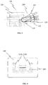
- FIG. 1 depicts a fiber optic ferrule adapter with a multi-fiber optic ferrule inserted therein in accordance to an embodiment of the present invention
- FIG. 2 a depicts the fiber optic ferrule adapter without the multi-fiber optic ferrule
- FIG. 2 b depicts its cross-sectional view from a plane cutting through a central line along the optical axis
- FIG. 3 shows a cross-sectional view from a plane cutting through a central line along the optical axis of the fiber optic ferrule adapter with a multi-fiber optic ferrule being inserted into (or extracted from) the cavity 301 during installation (or uninstallation);
- FIG. 4 shows a cross-sectional view from a plane cutting through two protrusions of the fiber optic ferrule adapter with the multi-fiber optic ferrule inserted therein;
- FIG. 5 a shows a perspective view of a ferrule removal tool in accordance to one embodiment of the present invention along with the fiber optic ferrule adapter;
- FIG. 5 b shows another perspective view of the ferrule removal tool along with the fiber optic ferrule adapter
- FIG. 6 a shows a perspective view of a ferrule removal tool in accordance to another embodiment of the present invention
- FIG. 6 b shows another perspective view of the ferrule removal tool along with the fiber optic ferrule adapter
- FIG. 7 a depicts the fiber optic ferrule adapter encased in an optional outer housing in accordance to one embodiment of the present invention
- FIG. 7 b depicts the fiber optic ferrule adapter and the optional outer housing before assembly
- FIG. 8 a shows a perspective view of the fiber optic ferrule adapter installed with an optional mounting plate
- FIG. 8 b shows another perspective view of the fiber optic ferrule adapter installed with the optional mounting plate
- FIG. 9 a depicts the fiber optic ferrule adapter installed with the optional mount plate inserted and secured in a connector panel
- FIG. 9 b depicts a plurality of fiber optic ferrule adapters installed with the optional mount plates inserted and secured in a multi-connector panel;
- FIG. 10 a depicts a fiber optic ferrule adapter with a multi-fiber optic ferrule inserted therein in accordance to another embodiment of the present invention
- FIG. 10 b depicts the fiber optic ferrule adapter and the multi-fiber optic ferrule before assembly
- FIG. 11 a depicts a ferrule removal tool in accordance to another embodiment of the present invention.
- FIG. 11 b depicts the ferrule removal tool being used to release the multi-fiber optic from the fiber optic ferrule adapter.
- FIG. 1 depicts an embodiment of a fiber optic ferrule adapter 100 with a multi-fiber optic ferrule 200 being inserted therein.
- the adapter 100 includes a holder 110 having a cavity for holding and securing the multi-fiber optic ferrule 200 therein and a receptacle housing 120 with an opening at the one end further away from the holder 110 that allows the insertion of a fiber optic connector.
- the holder 110 has a top facing opening for receiving the multi-fiber optic ferrule 200 into its cavity, and two protrusions 113 a and 113 b , which are respectively protruded from each interior side walls of the holder 110 , for latching the multi-fiber optic ferrule 200 in place.
- FIG. 2 a depicts a perspective view of the fiber optic ferrule adapter 100 without any multi-fiber optic ferrule being inserted.
- FIG. 2 b depicts its cross-sectional view from a plane cutting through a central line along the longitudinal axis of the fiber optic ferrule adapter 100 .
- the holder 110 further comprises a groove 115 recessed on three sides of the interior wall of the holder and a slope 114 next to the interface between the cavity of the holder 110 and the receptacle housing 120 .
- the groove 115 may be recessed on one side, which can be the bottom, or the two opposing sides of the interior wall of the holder.
- FIG. 3 shows a cross-sectional view from a plane cutting through a central line along the longitudinal axis of the fiber optic ferrule adapter 100 with a multi-fiber optic ferrule 200 being inserted into (or extracted from) the cavity of the holder 110 during installation (or uninstallation). It can be seen that during the insertion or extraction, the slope 114 allows the sliding of the multi-fiber optic ferrule 200 at an angle to the top of the fiber optic ferrule adapter 100 so as to ease the insertion or extraction of the multi-fiber optic ferrule.
- the groove 115 catches a ridge 201 on the multi-fiber optic ferrule and secures the multi-fiber optic ferrule in place so as to prevent any longitudinal movement of the multi-fiber optic ferrule along the longitudinal axis of the fiber optic ferrule adapter 100 inside the cavity of the holder 110 .
- FIG. 4 shows a cross-sectional view from a plane cutting through two protrusions 113 a and 113 b of the fiber optic ferrule adapter 100 with the multi-fiber optic ferrule 200 inserted therein. It can be seen that the two protrusions 113 a and 113 b latch the multi-fiber optic ferrule in place so as to prevent any up-down movement of the multi-fiber optic ferrule inside the cavity of the holder 110 .
- the protrusions 113 a and 113 b are in dome shape. In another embodiment, the protrusions 113 a and 113 b are in wedge shape.
- the present invention provides a ferrule removal tool 300 comprising two protrusions 301 a and 301 b as shown in FIG. 5 a . It can be seen from FIG. 5 b that the protrusions 301 a and 301 b can be inserted into a through-holes 116 a and 116 b respectively located at the bottom the holder 110 of the fiber optic ferrule adapter 100 .
- the protrusions 301 a and 301 b are configured with a length long enough to reach inside the cavity of the holder 110 when inserted fully into the through-holes 116 a and 116 b such that one can exert an upward pushing force on the multi-fiber optic ferrule 200 held within the cavity of the holder 110 . With an appropriate amount of upward pushing force, the multi-fiber optic ferrule 200 is forced out and released from the holder 110 .
- the ferrule removal tool 300 comprises one protrusion 301 as shown in FIG. 6 a .
- the holder 110 has one corresponding through-hole 116 as shown in FIG. 6 b .
- ferrule removal tools with three, four, five, etc. protrusions with corresponding number of through-hole in the holders are possible.
- the fiber optic ferrule adapter 100 may be encased inside an optional outer housing 400 when a multi-fiber optic ferrule 200 is held within the cavity 110 .
- the outer housing 400 is formed by a top shell 401 and a bottom shell 402 for sandwiching and holding the fiber optic ferrule adapter 100 and the multi-fiber optic ferrule 200 there in between.
- the fiber optic ferrule adapter 100 may be installed with an optional mount plate 500 .
- the mount plate 500 is installed on the receptacle housing 120 of the fiber optic ferrule adapter 100 .
- the mount plate 500 is further secured in a groove around the three sides of the receptacle housing 120 of the fiber optic ferrule adapter 100 main body, so to prevent any lateral movement of the mount plate 500 in respect with the fiber optic ferrule adapter 100 .
- FIG. 9 a depicts the fiber optic ferrule adapter 100 installed with the mount plate 500 inserted and secured in a connector panel 610 ; and
- FIG. 9 b depicts a plurality of fiber optic ferrule adapters 100 installed with the mount plates 500 inserted and secured in a multi-connector panel 620 .
- FIG. 10 a Shown in the figure is a fiber optic ferrule adapter 700 with a multi-fiber optic ferrule 200 inserted therein in accordance to another embodiment of the present invention.
- FIG. 10 b shows the fiber optic ferrule adapter 700 and the multi-fiber optic ferrule 200 before assembly.
- the adapter 700 includes a holder 710 having a cavity for holding and securing the multi-fiber optic ferrule therein and a receptacle housing 720 with an opening at the one end further away from the holder 710 that allows the insertion of a fiber optic connector.
- the holder 710 has a front facing opening at the one end distal from the receptacle housing 720 for receiving the multi-fiber optic ferrule 200 into its cavity.
- the adapter 700 further includes a retention cap 730 for securing the ferrule 200 within the holder 710 .
- the cap 730 comprises an attachment means for attaching to the adapter 700 body.
- the attachment means includes two arms 731 a and 731 b with a hook or wedge on each of the arms 731 a and 731 b for interlocking with corresponding indentations or through-holes on the adapter 700 body, such that once attached, the retention cap 730 holds the multi-fiber optic ferrule 200 tightly within the holder 710 and prevents longitudinal movement of the multi-fiber optic ferrule 200 inside the cavity of the holder 710 .
- ferrule removal tool 800 As shown in FIG. 11 a , The ferrule removal tool 800 comprises a handle 820 and a frontend 810 with two extensions 811 a and 811 b at the end distal from the handle 820 . As shown in FIG. 11 b , the ferrule removal tool 800 operates on the assembled fiber optic ferrule adapter 700 by inserting the frontend 810 into the vacated receptacle housing 720 until the two extensions 811 a and 811 b come in contact with the retention cap arms 731 a and 731 b .
- the two extensions 811 a and 811 b push retention cap arms 731 a and 731 b the detach the retention cap 730 from the adapter 700 body, thereby releasing the multi-fiber optic ferrule 200 inside the cavity of the holder 710 .
Abstract
Description
Claims (14)
Priority Applications (2)
| Application Number | Priority Date | Filing Date | Title |
|---|---|---|---|
| US15/796,969 US10761273B2 (en) | 2017-06-13 | 2017-10-30 | Snap in fiber optic ferrule adapter |
| US17/007,125 US11372168B2 (en) | 2017-06-13 | 2020-08-31 | Snap in fiber optic ferrule adapter with retention cap |
Applications Claiming Priority (2)
| Application Number | Priority Date | Filing Date | Title |
|---|---|---|---|
| US201762519162P | 2017-06-13 | 2017-06-13 | |
| US15/796,969 US10761273B2 (en) | 2017-06-13 | 2017-10-30 | Snap in fiber optic ferrule adapter |
Related Child Applications (1)
| Application Number | Title | Priority Date | Filing Date |
|---|---|---|---|
| US17/007,125 Continuation US11372168B2 (en) | 2017-06-13 | 2020-08-31 | Snap in fiber optic ferrule adapter with retention cap |
Publications (2)
| Publication Number | Publication Date |
|---|---|
| US20180356600A1 US20180356600A1 (en) | 2018-12-13 |
| US10761273B2 true US10761273B2 (en) | 2020-09-01 |
Family
ID=64563310
Family Applications (2)
| Application Number | Title | Priority Date | Filing Date |
|---|---|---|---|
| US15/796,969 Active US10761273B2 (en) | 2017-06-13 | 2017-10-30 | Snap in fiber optic ferrule adapter |
| US17/007,125 Active US11372168B2 (en) | 2017-06-13 | 2020-08-31 | Snap in fiber optic ferrule adapter with retention cap |
Family Applications After (1)
| Application Number | Title | Priority Date | Filing Date |
|---|---|---|---|
| US17/007,125 Active US11372168B2 (en) | 2017-06-13 | 2020-08-31 | Snap in fiber optic ferrule adapter with retention cap |
Country Status (2)
| Country | Link |
|---|---|
| US (2) | US10761273B2 (en) |
| CN (2) | CN112241052B (en) |
Cited By (1)
| Publication number | Priority date | Publication date | Assignee | Title |
|---|---|---|---|---|
| US11237339B2 (en) | 2018-12-20 | 2022-02-01 | Us Conec, Ltd. | Secure MT ferrule latching with MPO adapter |
Families Citing this family (3)
| Publication number | Priority date | Publication date | Assignee | Title |
|---|---|---|---|---|
| WO2021016431A1 (en) * | 2019-07-23 | 2021-01-28 | Senko Advanced Components, Inc | Ultra-small form factor receptacle for receiving a fiber optic connector opposing a ferrule assembly |
| JP2021081717A (en) * | 2019-11-15 | 2021-05-27 | 株式会社精工技研 | Connector plug and stopper for connector plug |
| CN116400461B (en) * | 2023-03-02 | 2024-01-02 | 宁波莱塔思光学科技有限公司 | Male-female compatible multi-optical-fiber adapter |
Citations (13)
| Publication number | Priority date | Publication date | Assignee | Title |
|---|---|---|---|---|
| JPH1123908A (en) | 1997-06-27 | 1999-01-29 | New Japan Radio Co Ltd | Adapter for mt connector |
| US5940561A (en) * | 1997-04-23 | 1999-08-17 | Siecor Corporation | Adapter assembly for precise alignment of fiber optic connectors |
| US6095695A (en) | 1996-10-28 | 2000-08-01 | Sumitomo Electric Industries, Ltd. | Optical connector, and using method and tool thereof |
| US6146192A (en) * | 1999-03-31 | 2000-11-14 | Adc Telecommunications, Inc. | Bulkhead connector system including angled adapter |
| JP2000338367A (en) | 1999-05-28 | 2000-12-08 | Fujikura Ltd | Optical connector and its connecting method |
| US6632023B1 (en) | 1998-08-04 | 2003-10-14 | Sumitomo Electric Industries, Ltd. | Optical module connector adaptor |
| US20050220422A1 (en) | 2004-04-01 | 2005-10-06 | Harris Corporation | Ruggedized module for securely retaining multi-optical fiber interconnect ferrules |
| US7029322B2 (en) * | 2003-02-27 | 2006-04-18 | Molex Incorporated | Connector panel mount system |
| US7296935B1 (en) | 2007-02-09 | 2007-11-20 | Us Conec, Ltd. | Ferrule adapter and ferrule adapter assembly |
| US8157454B2 (en) | 2007-02-05 | 2012-04-17 | Yamaichi Electronics Co., Ltd. | Releasable locking mechanism for optical connector |
| US20130188912A1 (en) * | 2010-10-01 | 2013-07-25 | Tyco Electronics Amp Gmbh | Optical swing connector, optical counter connector as well as optical connecting unit |
| US20140270646A1 (en) * | 2013-03-15 | 2014-09-18 | Tyco Electronics Corporation | Optical connector housing assembly with dual insertion and extraction options |
| US20150093078A1 (en) * | 2013-09-27 | 2015-04-02 | Formerica Optoelectronics Inc. | Connector |
Family Cites Families (8)
| Publication number | Priority date | Publication date | Assignee | Title |
|---|---|---|---|---|
| JP3209044B2 (en) * | 1995-06-13 | 2001-09-17 | 住友電装株式会社 | Optical connector and method of fixing optical fiber to optical connector |
| US8052334B2 (en) * | 2008-02-21 | 2011-11-08 | US Conec, Ltd | Field installable ferrule and tool and method for installing optical fibers in the ferrule using the tool |
| JP4766619B2 (en) * | 2008-07-22 | 2011-09-07 | 日本航空電子工業株式会社 | Optical adapter |
| US9261654B2 (en) * | 2009-10-13 | 2016-02-16 | Leviton Manufacturing Co., Inc. | Fiber optic adapter plates with integrated fiber optic adapters |
| CN102116907B (en) * | 2009-12-30 | 2013-03-13 | 富士康(昆山)电脑接插件有限公司 | Photoelectric connector and combination thereof |
| US8974124B2 (en) * | 2012-08-16 | 2015-03-10 | Senko Advanced Components, Inc. | Fiber optic connector |
| US9768901B2 (en) * | 2014-11-20 | 2017-09-19 | Kaiam Corp. | Planar lightwave circuit active connector |
| CN104932063B (en) * | 2015-06-29 | 2016-08-24 | 周其 | A kind of joints of optical fibre device for clamping and rotating |
-
2017
- 2017-10-30 US US15/796,969 patent/US10761273B2/en active Active
-
2018
- 2018-02-08 CN CN202011244215.XA patent/CN112241052B/en active Active
- 2018-02-08 CN CN201810129920.1A patent/CN109085678B/en active Active
-
2020
- 2020-08-31 US US17/007,125 patent/US11372168B2/en active Active
Patent Citations (13)
| Publication number | Priority date | Publication date | Assignee | Title |
|---|---|---|---|---|
| US6095695A (en) | 1996-10-28 | 2000-08-01 | Sumitomo Electric Industries, Ltd. | Optical connector, and using method and tool thereof |
| US5940561A (en) * | 1997-04-23 | 1999-08-17 | Siecor Corporation | Adapter assembly for precise alignment of fiber optic connectors |
| JPH1123908A (en) | 1997-06-27 | 1999-01-29 | New Japan Radio Co Ltd | Adapter for mt connector |
| US6632023B1 (en) | 1998-08-04 | 2003-10-14 | Sumitomo Electric Industries, Ltd. | Optical module connector adaptor |
| US6146192A (en) * | 1999-03-31 | 2000-11-14 | Adc Telecommunications, Inc. | Bulkhead connector system including angled adapter |
| JP2000338367A (en) | 1999-05-28 | 2000-12-08 | Fujikura Ltd | Optical connector and its connecting method |
| US7029322B2 (en) * | 2003-02-27 | 2006-04-18 | Molex Incorporated | Connector panel mount system |
| US20050220422A1 (en) | 2004-04-01 | 2005-10-06 | Harris Corporation | Ruggedized module for securely retaining multi-optical fiber interconnect ferrules |
| US8157454B2 (en) | 2007-02-05 | 2012-04-17 | Yamaichi Electronics Co., Ltd. | Releasable locking mechanism for optical connector |
| US7296935B1 (en) | 2007-02-09 | 2007-11-20 | Us Conec, Ltd. | Ferrule adapter and ferrule adapter assembly |
| US20130188912A1 (en) * | 2010-10-01 | 2013-07-25 | Tyco Electronics Amp Gmbh | Optical swing connector, optical counter connector as well as optical connecting unit |
| US20140270646A1 (en) * | 2013-03-15 | 2014-09-18 | Tyco Electronics Corporation | Optical connector housing assembly with dual insertion and extraction options |
| US20150093078A1 (en) * | 2013-09-27 | 2015-04-02 | Formerica Optoelectronics Inc. | Connector |
Cited By (1)
| Publication number | Priority date | Publication date | Assignee | Title |
|---|---|---|---|---|
| US11237339B2 (en) | 2018-12-20 | 2022-02-01 | Us Conec, Ltd. | Secure MT ferrule latching with MPO adapter |
Also Published As
| Publication number | Publication date |
|---|---|
| US11372168B2 (en) | 2022-06-28 |
| CN112241052B (en) | 2022-07-08 |
| US20180356600A1 (en) | 2018-12-13 |
| CN109085678A (en) | 2018-12-25 |
| US20200393626A1 (en) | 2020-12-17 |
| CN109085678B (en) | 2020-12-01 |
| CN112241052A (en) | 2021-01-19 |
Similar Documents
| Publication | Publication Date | Title |
|---|---|---|
| US20200393626A1 (en) | Snap in fiber optic ferrule adapter with retention cap | |
| ES2906963T3 (en) | Multi-port assemblies including retention features | |
| KR102239204B1 (en) | Narrow width adapters and connectors with modular latching arms | |
| US10120138B2 (en) | Connector with trigger locking feature, and cable assemblies and methods including the same | |
| US9261653B2 (en) | Fiber optic plug assembly and optical connector system | |
| KR101459158B1 (en) | Fiber optic splitter module | |
| JP4833802B2 (en) | Optical connector connection structure | |
| US20080131055A1 (en) | Keyed push-pull type fiber optic connection system | |
| US10416394B2 (en) | Fiber optic receptacle with integrated device therein | |
| US20200310049A1 (en) | Mpo microlatch lock connector | |
| JP2009265208A (en) | Multiple optical adapter | |
| US9146351B2 (en) | Loopback housing for a fiber optic connector | |
| JP2011027876A (en) | Multiple-connection optical connector | |
| US11385428B2 (en) | Cassette assembly for a plural of fiber optic receptacles | |
| US20150117820A1 (en) | Optical fiber adapter with shutter member | |
| JP7084195B2 (en) | Mini adapter for MPO plug | |
| US9482828B2 (en) | One-piece alignment socket holder with locking means | |
| CN114730049A (en) | Card sleeve pusher | |
| US11860426B2 (en) | Dust plug for adapter pre-populated with MPO housing | |
| EP1298470B1 (en) | Optical connector system | |
| EP3707541B1 (en) | Shroud for sc optical connector | |
| CN110799872A (en) | Optical connector and push-pull member | |
| CN114815080B (en) | Connector, adapter, connection assembly, disconnecting tool and cable | |
| CN114830001A (en) | Cover for fiber optic ferrule and ferrule pusher | |
| CN113966479A (en) | Wall-mounted optical connector and assembly thereof |
Legal Events
| Date | Code | Title | Description |
|---|---|---|---|
| AS | Assignment |
Owner name: SENKO ADVANCED COMPONENTS, INC., MASSACHUSETTS Free format text: ASSIGNMENT OF ASSIGNORS INTEREST;ASSIGNORS:TAKANO, KAZUYOSHI;IIZUMI, KENJI;SIGNING DATES FROM 20170616 TO 20171026;REEL/FRAME:043978/0727 |
|
| FEPP | Fee payment procedure |
Free format text: ENTITY STATUS SET TO UNDISCOUNTED (ORIGINAL EVENT CODE: BIG.); ENTITY STATUS OF PATENT OWNER: SMALL ENTITY |
|
| FEPP | Fee payment procedure |
Free format text: ENTITY STATUS SET TO SMALL (ORIGINAL EVENT CODE: SMAL); ENTITY STATUS OF PATENT OWNER: SMALL ENTITY |
|
| STPP | Information on status: patent application and granting procedure in general |
Free format text: NON FINAL ACTION MAILED |
|
| STPP | Information on status: patent application and granting procedure in general |
Free format text: RESPONSE TO NON-FINAL OFFICE ACTION ENTERED AND FORWARDED TO EXAMINER |
|
| AS | Assignment |
Owner name: SENKO ADVANCED COMPONENTS, INC, MASSACHUSETTS Free format text: ASSIGNMENT OF ASSIGNORS INTEREST;ASSIGNORS:TAKANO, KAZUYOSHI;IIZUMI, KENJI;SIGNING DATES FROM 20190401 TO 20190410;REEL/FRAME:049282/0609 |
|
| STPP | Information on status: patent application and granting procedure in general |
Free format text: FINAL REJECTION MAILED |
|
| STPP | Information on status: patent application and granting procedure in general |
Free format text: DOCKETED NEW CASE - READY FOR EXAMINATION |
|
| STPP | Information on status: patent application and granting procedure in general |
Free format text: NOTICE OF ALLOWANCE MAILED -- APPLICATION RECEIVED IN OFFICE OF PUBLICATIONS |
|
| STPP | Information on status: patent application and granting procedure in general |
Free format text: DOCKETED NEW CASE - READY FOR EXAMINATION |
|
| STPP | Information on status: patent application and granting procedure in general |
Free format text: NOTICE OF ALLOWANCE MAILED -- APPLICATION RECEIVED IN OFFICE OF PUBLICATIONS |
|
| STCF | Information on status: patent grant |
Free format text: PATENTED CASE |
|
| FEPP | Fee payment procedure |
Free format text: ENTITY STATUS SET TO UNDISCOUNTED (ORIGINAL EVENT CODE: BIG.); ENTITY STATUS OF PATENT OWNER: LARGE ENTITY |
|
| MAFP | Maintenance fee payment |
Free format text: PAYMENT OF MAINTENANCE FEE, 4TH YEAR, LARGE ENTITY (ORIGINAL EVENT CODE: M1551); ENTITY STATUS OF PATENT OWNER: LARGE ENTITY Year of fee payment: 4 |