US10761206B2 - Soil measurement system using wireless signals - Google Patents
Soil measurement system using wireless signals Download PDFInfo
- Publication number
- US10761206B2 US10761206B2 US16/154,483 US201816154483A US10761206B2 US 10761206 B2 US10761206 B2 US 10761206B2 US 201816154483 A US201816154483 A US 201816154483A US 10761206 B2 US10761206 B2 US 10761206B2
- Authority
- US
- United States
- Prior art keywords
- soil
- permittivity
- antennas
- estimated
- subterranean
- Prior art date
- Legal status (The legal status is an assumption and is not a legal conclusion. Google has not performed a legal analysis and makes no representation as to the accuracy of the status listed.)
- Active, expires
Links
- 239000002689 soil Substances 0.000 title claims abstract description 407
- 238000005259 measurement Methods 0.000 title claims abstract description 67
- 239000000463 material Substances 0.000 claims abstract description 43
- 238000001228 spectrum Methods 0.000 claims abstract description 25
- 230000006870 function Effects 0.000 claims description 16
- 238000004891 communication Methods 0.000 claims description 12
- 238000000691 measurement method Methods 0.000 claims description 11
- 238000010801 machine learning Methods 0.000 claims description 8
- 230000002093 peripheral effect Effects 0.000 claims description 7
- 238000011160 research Methods 0.000 claims description 5
- 238000000034 method Methods 0.000 description 57
- XLYOFNOQVPJJNP-UHFFFAOYSA-N water Substances O XLYOFNOQVPJJNP-UHFFFAOYSA-N 0.000 description 18
- 238000003860 storage Methods 0.000 description 15
- 238000002474 experimental method Methods 0.000 description 12
- 239000003570 air Substances 0.000 description 9
- 230000008859 change Effects 0.000 description 8
- 230000005540 biological transmission Effects 0.000 description 7
- 238000004382 potting Methods 0.000 description 7
- 238000012545 processing Methods 0.000 description 6
- 238000000926 separation method Methods 0.000 description 6
- 230000000694 effects Effects 0.000 description 5
- 238000005516 engineering process Methods 0.000 description 5
- -1 cinder-block Substances 0.000 description 4
- 238000013461 design Methods 0.000 description 4
- 230000009021 linear effect Effects 0.000 description 4
- 238000004422 calculation algorithm Methods 0.000 description 3
- 230000002262 irrigation Effects 0.000 description 3
- 238000003973 irrigation Methods 0.000 description 3
- 239000011159 matrix material Substances 0.000 description 3
- 239000002245 particle Substances 0.000 description 3
- 101000667353 Homo sapiens von Willebrand factor A domain-containing protein 1 Proteins 0.000 description 2
- 238000013459 approach Methods 0.000 description 2
- 239000010426 asphalt Substances 0.000 description 2
- 239000011449 brick Substances 0.000 description 2
- 239000004567 concrete Substances 0.000 description 2
- 230000007423 decrease Effects 0.000 description 2
- 230000001934 delay Effects 0.000 description 2
- 230000001419 dependent effect Effects 0.000 description 2
- 238000001514 detection method Methods 0.000 description 2
- 239000011152 fibreglass Substances 0.000 description 2
- 239000006260 foam Substances 0.000 description 2
- 239000003973 paint Substances 0.000 description 2
- 239000011505 plaster Substances 0.000 description 2
- 239000004033 plastic Substances 0.000 description 2
- 229920003023 plastic Polymers 0.000 description 2
- 230000008569 process Effects 0.000 description 2
- 238000005070 sampling Methods 0.000 description 2
- 239000004576 sand Substances 0.000 description 2
- 230000000007 visual effect Effects 0.000 description 2
- 102100039759 von Willebrand factor A domain-containing protein 1 Human genes 0.000 description 2
- 239000002023 wood Substances 0.000 description 2
- 101000822695 Clostridium perfringens (strain 13 / Type A) Small, acid-soluble spore protein C1 Proteins 0.000 description 1
- 101000655262 Clostridium perfringens (strain 13 / Type A) Small, acid-soluble spore protein C2 Proteins 0.000 description 1
- 101000655256 Paraclostridium bifermentans Small, acid-soluble spore protein alpha Proteins 0.000 description 1
- 101000655264 Paraclostridium bifermentans Small, acid-soluble spore protein beta Proteins 0.000 description 1
- 239000008186 active pharmaceutical agent Substances 0.000 description 1
- 238000004458 analytical method Methods 0.000 description 1
- 238000003491 array Methods 0.000 description 1
- 230000003190 augmentative effect Effects 0.000 description 1
- 230000006399 behavior Effects 0.000 description 1
- 230000007177 brain activity Effects 0.000 description 1
- 238000004364 calculation method Methods 0.000 description 1
- 239000003990 capacitor Substances 0.000 description 1
- 239000000919 ceramic Substances 0.000 description 1
- 238000004590 computer program Methods 0.000 description 1
- 239000000356 contaminant Substances 0.000 description 1
- 230000006735 deficit Effects 0.000 description 1
- 238000011982 device technology Methods 0.000 description 1
- 238000009792 diffusion process Methods 0.000 description 1
- 238000001035 drying Methods 0.000 description 1
- 230000005684 electric field Effects 0.000 description 1
- 238000009313 farming Methods 0.000 description 1
- 239000003337 fertilizer Substances 0.000 description 1
- 238000009499 grossing Methods 0.000 description 1
- 239000003673 groundwater Substances 0.000 description 1
- 230000036541 health Effects 0.000 description 1
- 229910052500 inorganic mineral Inorganic materials 0.000 description 1
- 238000013507 mapping Methods 0.000 description 1
- 239000011707 mineral Substances 0.000 description 1
- 239000000203 mixture Substances 0.000 description 1
- 238000010295 mobile communication Methods 0.000 description 1
- 230000009022 nonlinear effect Effects 0.000 description 1
- 238000010606 normalization Methods 0.000 description 1
- 235000021232 nutrient availability Nutrition 0.000 description 1
- 230000003287 optical effect Effects 0.000 description 1
- 238000000643 oven drying Methods 0.000 description 1
- 238000004806 packaging method and process Methods 0.000 description 1
- 230000000149 penetrating effect Effects 0.000 description 1
- 230000010363 phase shift Effects 0.000 description 1
- 238000003672 processing method Methods 0.000 description 1
- 230000001902 propagating effect Effects 0.000 description 1
- 230000002285 radioactive effect Effects 0.000 description 1
- 238000002310 reflectometry Methods 0.000 description 1
- 230000004044 response Effects 0.000 description 1
- 150000003839 salts Chemical class 0.000 description 1
- 239000000523 sample Substances 0.000 description 1
- 238000011012 sanitization Methods 0.000 description 1
- 238000013515 script Methods 0.000 description 1
- 239000004065 semiconductor Substances 0.000 description 1
- 230000003068 static effect Effects 0.000 description 1
- 238000012706 support-vector machine Methods 0.000 description 1
- 230000001360 synchronised effect Effects 0.000 description 1
- 239000008399 tap water Substances 0.000 description 1
- 235000020679 tap water Nutrition 0.000 description 1
- 238000012360 testing method Methods 0.000 description 1
- 230000026683 transduction Effects 0.000 description 1
- 238000010361 transduction Methods 0.000 description 1
- 238000005303 weighing Methods 0.000 description 1
Images


Classifications
-
- G—PHYSICS
- G01—MEASURING; TESTING
- G01S—RADIO DIRECTION-FINDING; RADIO NAVIGATION; DETERMINING DISTANCE OR VELOCITY BY USE OF RADIO WAVES; LOCATING OR PRESENCE-DETECTING BY USE OF THE REFLECTION OR RERADIATION OF RADIO WAVES; ANALOGOUS ARRANGEMENTS USING OTHER WAVES
- G01S13/00—Systems using the reflection or reradiation of radio waves, e.g. radar systems; Analogous systems using reflection or reradiation of waves whose nature or wavelength is irrelevant or unspecified
- G01S13/88—Radar or analogous systems specially adapted for specific applications
- G01S13/885—Radar or analogous systems specially adapted for specific applications for ground probing
-
- A—HUMAN NECESSITIES
- A01—AGRICULTURE; FORESTRY; ANIMAL HUSBANDRY; HUNTING; TRAPPING; FISHING
- A01B—SOIL WORKING IN AGRICULTURE OR FORESTRY; PARTS, DETAILS, OR ACCESSORIES OF AGRICULTURAL MACHINES OR IMPLEMENTS, IN GENERAL
- A01B47/00—Soil-working with electric potential applied between tools and soil
-
- A—HUMAN NECESSITIES
- A01—AGRICULTURE; FORESTRY; ANIMAL HUSBANDRY; HUNTING; TRAPPING; FISHING
- A01B—SOIL WORKING IN AGRICULTURE OR FORESTRY; PARTS, DETAILS, OR ACCESSORIES OF AGRICULTURAL MACHINES OR IMPLEMENTS, IN GENERAL
- A01B79/00—Methods for working soil
- A01B79/02—Methods for working soil combined with other agricultural processing, e.g. fertilising, planting
-
- G—PHYSICS
- G01—MEASURING; TESTING
- G01N—INVESTIGATING OR ANALYSING MATERIALS BY DETERMINING THEIR CHEMICAL OR PHYSICAL PROPERTIES
- G01N27/00—Investigating or analysing materials by the use of electric, electrochemical, or magnetic means
- G01N27/02—Investigating or analysing materials by the use of electric, electrochemical, or magnetic means by investigating impedance
- G01N27/04—Investigating or analysing materials by the use of electric, electrochemical, or magnetic means by investigating impedance by investigating resistance
- G01N27/048—Investigating or analysing materials by the use of electric, electrochemical, or magnetic means by investigating impedance by investigating resistance for determining moisture content of the material
-
- G—PHYSICS
- G01—MEASURING; TESTING
- G01N—INVESTIGATING OR ANALYSING MATERIALS BY DETERMINING THEIR CHEMICAL OR PHYSICAL PROPERTIES
- G01N33/00—Investigating or analysing materials by specific methods not covered by groups G01N1/00 - G01N31/00
- G01N33/24—Earth materials
- G01N33/245—Earth materials for agricultural purposes
-
- G—PHYSICS
- G01—MEASURING; TESTING
- G01N—INVESTIGATING OR ANALYSING MATERIALS BY DETERMINING THEIR CHEMICAL OR PHYSICAL PROPERTIES
- G01N33/00—Investigating or analysing materials by specific methods not covered by groups G01N1/00 - G01N31/00
- G01N33/24—Earth materials
- G01N33/246—Earth materials for water content
-
- G—PHYSICS
- G01—MEASURING; TESTING
- G01S—RADIO DIRECTION-FINDING; RADIO NAVIGATION; DETERMINING DISTANCE OR VELOCITY BY USE OF RADIO WAVES; LOCATING OR PRESENCE-DETECTING BY USE OF THE REFLECTION OR RERADIATION OF RADIO WAVES; ANALOGOUS ARRANGEMENTS USING OTHER WAVES
- G01S13/00—Systems using the reflection or reradiation of radio waves, e.g. radar systems; Analogous systems using reflection or reradiation of waves whose nature or wavelength is irrelevant or unspecified
- G01S13/88—Radar or analogous systems specially adapted for specific applications
-
- G—PHYSICS
- G01—MEASURING; TESTING
- G01V—GEOPHYSICS; GRAVITATIONAL MEASUREMENTS; DETECTING MASSES OR OBJECTS; TAGS
- G01V3/00—Electric or magnetic prospecting or detecting; Measuring magnetic field characteristics of the earth, e.g. declination, deviation
- G01V3/12—Electric or magnetic prospecting or detecting; Measuring magnetic field characteristics of the earth, e.g. declination, deviation operating with electromagnetic waves
-
- H—ELECTRICITY
- H04—ELECTRIC COMMUNICATION TECHNIQUE
- H04B—TRANSMISSION
- H04B13/00—Transmission systems characterised by the medium used for transmission, not provided for in groups H04B3/00 - H04B11/00
- H04B13/02—Transmission systems in which the medium consists of the earth or a large mass of water thereon, e.g. earth telegraphy
-
- A—HUMAN NECESSITIES
- A01—AGRICULTURE; FORESTRY; ANIMAL HUSBANDRY; HUNTING; TRAPPING; FISHING
- A01G—HORTICULTURE; CULTIVATION OF VEGETABLES, FLOWERS, RICE, FRUIT, VINES, HOPS OR SEAWEED; FORESTRY; WATERING
- A01G25/00—Watering gardens, fields, sports grounds or the like
- A01G25/16—Control of watering
- A01G25/167—Control by humidity of the soil itself or of devices simulating soil or of the atmosphere; Soil humidity sensors
-
- G—PHYSICS
- G01—MEASURING; TESTING
- G01N—INVESTIGATING OR ANALYSING MATERIALS BY DETERMINING THEIR CHEMICAL OR PHYSICAL PROPERTIES
- G01N27/00—Investigating or analysing materials by the use of electric, electrochemical, or magnetic means
- G01N27/02—Investigating or analysing materials by the use of electric, electrochemical, or magnetic means by investigating impedance
- G01N27/026—Dielectric impedance spectroscopy
-
- G—PHYSICS
- G01—MEASURING; TESTING
- G01N—INVESTIGATING OR ANALYSING MATERIALS BY DETERMINING THEIR CHEMICAL OR PHYSICAL PROPERTIES
- G01N27/00—Investigating or analysing materials by the use of electric, electrochemical, or magnetic means
- G01N27/02—Investigating or analysing materials by the use of electric, electrochemical, or magnetic means by investigating impedance
- G01N27/04—Investigating or analysing materials by the use of electric, electrochemical, or magnetic means by investigating impedance by investigating resistance
- G01N27/043—Investigating or analysing materials by the use of electric, electrochemical, or magnetic means by investigating impedance by investigating resistance of a granular material
Definitions
- Soil moisture and soil electrical conductivity (EC) of a farm are important parameters for data-driven farming. This knowledge can help a farmer improve crop yield, reduce costs, and practice sustainable agriculture.
- a soil measurement system comprising a soil surveying device, a radio receiver, a plurality of subterranean antennas, and a processor.
- the soil surveying device comprises a wireless radio transmitter configured to emit a wireless signal at a predetermined bandwidth in a predetermined spectrum.
- the plurality of subterranean antennas are in an array electronically connected to the radio receiver and configured to be mounted in a subterranean environment at different depths in the subterranean environment.
- Each of the plurality of subterranean antennas is configured to receive the wireless signal at a respective point in time.
- the processor is configured to determine a relative time of flight of the received wireless signal between the plurality of antennas at the respective point in time, and estimate a soil permittivity based on the determined relative time of flight.
- a measurement system is provided similar to that described above, which measures permittivity in mediums not limited to soil.
- FIG. 1 shows a soil measurement system according to one implementation of the present disclosure.
- FIG. 2 schematically shows a model of a plane wave propagating through an air-to-soil surface.
- FIG. 3 is a schematic illustration of an antenna array setup in soil.
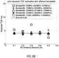
- FIGS. 4A-4C plot the signal attenuation in soil for the three receive antennas at three different depths as measured by a network analyzer.
- FIGS. 5A-5C illustrate an exemplary soil measurement setup for the soil measurement system according to one implementation of the present disclosure.
- FIGS. 6A-6C plot the relative time of flight (ToF) and absolute ToF estimation results given by the joint estimation method and the separate estimation method.
- FIGS. 7A-7C plot the soil dielectric permittivity estimation results based on relative ToF.
- FIGS. 8A-8C illustrate the different soil types used in the experimental examples.
- FIGS. 9A-9D plot different soil permittivity and EC estimation results for different soil types and salinity levels.
- FIGS. 10A-10C plot soil permittivity, EC, and imaginary effective permittivity estimation results as measured by a soil sensor, Universal Software Radio Peripheral (USRP), and Wireless Open-Access Research Platform (WARP) at different frequencies.
- USRP Universal Software Radio Peripheral
- WARP Wireless Open-Access Research Platform
- FIG. 11 shows a soil measurement method according to one implementation of the present disclosure.
- FIG. 12 shows a computing system according to an implementation of the present disclosure.
- GPRs Ground Penetrating Radars
- ToF time of flight
- ToF estimation requires ultra-wide bandwidth to obtain good performance.
- the bandwidth of systems like GPRs usually spans multiple GHz.
- Such systems also require specially designed hardware to allow operation on a wide bandwidth.
- ToF-based RF sensing techniques such as GPRs and TDRs, exploit the relationship between electromagnetic (EM) wave characteristics and material properties.
- EM electromagnetic
- Two key material properties that enable RF-based sensing are dielectric permittivity and EC. Compared with wave propagation in free space, larger permittivity and EC values in soils add attenuation to the signal strength and slow down the wave propagation speed. Conversely, knowing the attenuation and velocity of a signal traveling in a soil can help to figure out the permittivity and EC of that soil.
- the relationship between material properties and wave propagation will be mathematically explained.
- Equation (1) ⁇ 0 is the permittivity of free space (8:854 ⁇ 10 ⁇ 12 F/m). EC is usually represented by a real value, ⁇ , since its imaginary component is insignificant at radio frequencies.
- Permittivity in F/m
- EC in S/m
- Equations (2)-(4) ⁇ and ⁇ are the attenuation coefficient that determines signal attenuation and the phase coefficient that determines phase variation during propagation, respectively. It will be appreciated that c is the speed of light and A is the signal amplitude determined by wavelength in the medium and system parameters including antenna beam pattern, gain settings at transmitter and receiver, and antenna gains.
- Equation (5) P r is the transmit power, and G t and G r are the transmit and receive antenna gains, respectively.
- the wave propagation in free space is given as:
- the dielectric medium basically adds an extra attenuation due to the change of wavelength ⁇ 0 / ⁇ and the transmission loss e ⁇ d , and slows down the speed of wave by a factor of ⁇ / ⁇ 0 .
- the propagation velocity can be expressed as follows:
- K a is known as the apparent permittivity of a material, which is often adopted in ToF-based RF techniques to describe the permittivity estimated from ToF.
- the typical range of ⁇ square root over (K a ) ⁇ in soil is 2-6, corresponding to 2-6 times slowdown of wave speed in soil compared with the speed of light.
- ToF-based RF techniques measure ToF to estimate wave velocity v and then determine the apparent permittivity K a of soil.
- the relationship between K a and ToF of a signal traveling through a known distance d is given as follows:
- Soil is considered as a mixture of soil particles, water and air.
- the permittivity of soil strongly depends on the water content in it since water has a much larger permittivity than air and soil particles.
- the permittivity of water is around 80, while the permittivity of air is 1 and the permittivity of soil particles is from 3 to 10.
- the water content-permittivity relationship of soils has been well studied and modeled. Once the permittivity value of a soil is obtained, it can be fit into existing water content-permittivity models for that soil type to estimate the water content.
- Equation (11) ⁇ is the volumetric water content in soil and K a is the soil apparent permittivity.
- RF techniques measure the signal attenuation e ⁇ d through a known distance d to estimate the attenuation coefficient ⁇ and then use a to estimate EC.
- Equation (12) can be calculated from Equation (3).
- ⁇ a /2 ⁇ f ⁇ 0 ⁇ ′ r is a small value
- the calculation of ⁇ a can be simplified to
- ⁇ a ⁇ ⁇ ⁇ r ′ 60 ⁇ ⁇ ⁇ ( 13 )
- the present inventors developed a low-cost soil measurement system, which estimates soil moisture and soil EC without the need for a costly sensor, and can be used to estimate moisture and EC of other mediums as well. Instead, the system utilizes the phenomenon that RF waves travel slower in soil with higher permittivity. With a plurality of antennas in soil or other medium, the system can estimate the permittivity, and the corresponding moisture and EC levels of soil or other medium at the location of the antennas.
- system 10 comprises a soil surveying device 40 , a radio receiver device 20 , a plurality of subterranean antennas 22 a , 22 b , and 22 c , and a processor 46 as well as non-volatile memory 47 and volatile memory 48 .
- the soil surveying device 40 may also include a display 49 .
- the system 10 is configured to measure soil moisture and soil EC using Wi-Fi wireless signals.
- An antenna 42 on a Wi-Fi wireless radio transmitter 44 on a soil surveying device 40 such as a phone or on a tractor, transmits packets which are received by a plurality of antennas 22 a , 22 b , and 22 c on a radio receiver 20 in the soil. All antennas 22 a , 22 b , and 22 c are connected to a single radio receiver 20 .
- the received signal is used to estimate the permittivity of soil, which is then used to determine the soil moisture and soil EC.
- a soil surveying device 40 comprising a wireless radio transmitter 44 is configured to emit a wireless signal at a predetermined bandwidth in a predetermined spectrum.
- the predetermined spectrum is preferably 2.4 GHz, and the predetermined bandwidth is preferably 70 MHz, although 80 MHz or other suitable bandwidth range could be utilized.
- a plurality of subterranean antennas 22 a , 22 b , and 22 c in an antenna array 24 are electronically connected to the radio receiver 20 and configured to be mounted in a subterranean environment at different depths in the subterranean environment.
- Each of the plurality of subterranean antennas 22 a , 22 b , and 22 c is configured to receive the wireless signal at a respective point in time.
- the radio receiver 20 may also be provided with a processor 26 , non-volatile memory 27 , and volatile memory 28 .
- the system 10 is configured to sense soil moisture and soil EC using RF propagation in existing Wi-Fi bands. Specifically, the system 10 uses the unlicensed 2.4 GHz of spectrum, with multiple antennas 22 a , 22 b , and 22 c placed at different depths in the soil.
- a wireless transmitter 44 e.g. Wi-Fi, from the soil surveying device, emits signals that are received by these antennas 22 a , 22 b , and 22 c in the soil.
- the relative ToF or relative amplitude that are determined may then be transmitted back wirelessly by the multiple antennas 22 a , 22 b , and 22 c , by another transmitter provided on the radio receiver 20 , or transmitted by a wired connection to the soil surveying device 40 (which may function as the downstream computing device) housing the wireless radio transmitter 44 or to another downstream computing device.
- a processor of the radio receiver, the soil surveying device, or another downstream computing device may then compute the soil moisture, soil permittivity, and soil EC at the location of the antennas. This capability of the system 10 enables several new scenarios.
- a smartphone or tablet computer may be used as the soil surveying device that functions as the downstream computing device, and the wireless transmitter may be a WiFi transmitter equipped in a wireless network interface controller of the smartphone or tablet computer.
- the wireless transmitter may be a WiFi transmitter equipped in a wireless network interface controller of the smartphone or tablet computer.
- a tractor or an unmanned aerial vehicle (UAV) equipped with such smartphone or tablet computer devices can create new up-to-date maps of the soil every time they traverse the farm.
- An EC map can help a farmer build management zones.
- a sprinkler system can dynamically learn of moisture maps of the farm, and adapt the time of irrigation, and the amount of water that it uses in different regions.
- the system estimates the moisture and EC level from Wi-Fi signals. Due to poor propagation in 5 GHz of spectrum, the system preferably uses the 70 MHz of available spectrum in 2.4 GHz. Instead of measuring the absolute ToF, which would require a wide bandwidth, the system uses a technique to measure the relative ToF of the received signal between multiple antennas. The relative ToF is used to determine the permittivity and soil moisture. The soil EC is subsequently measured using the ratio of signal amplitudes on the different antennas.
- a processor 46 may be configured to determine a relative ToF of the received wireless signal between the plurality of subterranean antennas at the respective point in time, and estimate a soil permittivity based on the determined relative ToF.
- the processor 46 may further be configured to determine a relative amplitude or relative power at two of the plurality of subterranean antennas at different depths to estimate an attenuation coefficient, and estimate a soil electroconductivity based on the estimated attenuation coefficient and the estimated soil permittivity.
- a machine learning model may be used to receive, as input, vectorized covariance matrices of channel state information (CSI) of the wireless signal, and output the estimated soil permittivity, as described in further detail below.
- CSI channel state information
- a support vector machine executing a support vector regression model may be used as the machine learning model.
- the machine learning model may be extended to compute the permittivity of a material other than soil into which the antenna is inserted.
- the processor may be further configured to estimate a soil moisture level based on the estimated soil permittivity and/or the estimated soil electroconductivity.
- the processor 26 of the receiver 20 or a processor of another downstream computing device may be configured to determine the relative ToF and/or relative amplitude/relative power.
- the downstream computing device may be configured to output the estimated soil permittivity and/or the estimated soil electroconductivity via the display interface 49 .
- the processor may be further configured to transmit the estimated soil permittivity and/or the estimated soil electroconductivity via a wireless or wired connection to a downstream computing device, which may be the same device that transmitted the wireless signal to the receiver device, or which may be a different device.
- Wi-Fi transmissions in the unlicensed spectrum can be used to sense soil moisture and soil EC.
- System 10 may be implemented in the 2.4 GHz unlicensed bands over various hardware, including USRP, WARP, and a wireless network interface controller (NIC) such as Intel or Qualcomm Atheros based Wi-Fi cards, and system 10 has been demonstrated to perform as well as the more expensive soil sensors.
- NIC wireless network interface controller
- the wireless radio transmitter 44 and receiver device 20 of system 10 may each be selected from the group consisting of USRP, WARP, and wireless network interface controller (NIC) such as Intel Wi-Fi Link 5300 NIC and Atheros AR9590 Wi-Fi NIC to measure soil moisture and EC at 2.4 GHz, or other suitable frequency.
- NIC wireless network interface controller
- a wireless NIC serving as the wireless radio transmitter 44 may be provided in a portable computing device, such as a smartphone.
- USRP may be configured to perform wideband experiments for ground truthing.
- the WARP board may be configured to replicate CSI measurements similar to Wi-Fi cards, and microbenchmark the performance of the system.
- the present inventors implemented the system on two off-the-shelf Wi-Fi cards to validate results.
- USRP N200 devices with SBX daughterboards may operate on 400-4400 MHz, however, the transmission power of the SBX daughterboards drops as frequency increases. Therefore, measurements preferably use a bandwidth that spans from 400 MHz to 1400 MHz.
- One USRP device may be used as transmitter and the other as receiver.
- antennas may be switched during the measurements. For each antenna, the system sweeps through the 400-1400 MHz bandwidth with a step size of 5 MHz.
- phase-locked loop (PLL) offsets, carrier frequency offset (CFO), sampling frequency offset (SFO), and packet detection delay (PDD) are preferably consistent for all the receiver antennas.
- Two features may be employed on USRP to eliminate PLL offsets, CFO and SFO;
- SBX daughterboards have a PLL phase offset resync feature to synchronize PLL phase offsets on two USRPs after each frequency retune;
- Two devices can be connected with a MIMO cable to get time and frequency synchronization.
- a narrowband sinusoid may be used to estimate CSI.
- WARP boards and the Wi-Fi cards are both MIMO capable and can operate on 2.4 GHz and 5 GHz. With these two types of devices, the transmitter and receiver may not share oscillators. Therefore, a key challenge is to extract CSI information from PLL offsets, CFO, SFO, and PDD corrupted CSI data.
- the Intel Wi-Fi cards have a well-known issue of random phase jumps at 2.4 GHz while WARP boards and the Atheros cards do not have such an issue. Since WARP has better support for manual configuration, especially gain settings, the performance of the system is preferably evaluated with WARP. A fixed transmit power of 8 dBm may be used, which is much lower than the FCC-imposed power limit for 2.4 GHz channels.
- the Wi-Fi cards may be set into monitor mode using the open-source CSI tools on Linux, for example.
- the entire 70 MHz bandwidth at 2.4 GHz spectrum may be used to cope with potential multipath and amplitude variations that occur due to soil heterogeneity and antenna impedance change. To use the entire bandwidth, switching across the channels is performed. Therefore, there is a need to compensate for hardware impairments that lead to inconsistent measurements across channels.
- the calibration on WARP has two procedures. First, the PLL phase offsets are calibrated across channels by leveraging a key observation: although PLL phase offsets are different at different channels, they are constant after a frequency retune. Therefore, the PLL phase offsets at all the channels can be calibrated at the same time and do not need re-calibration unless nodes are reset.
- phase sanitization algorithm is adopted in SpotFi to equalize the impact of PDD and SFO on channel phase slopes across multiple channel measurements.
- the RF chains share the same PLL, their random phase behavior is simpler than WARP, which only has two possible states separated by n.
- a waterproof enclosure such as a box, may be used to protect the connectors of antennas as well as hold antennas at different depths in soil, and there may be a rod protruding from soil surface to indicate to farmers where the antennas are buried.
- FIG. 5B illustrates soil boxes protected by a tent.
- FIG. 5C illustrates a soil measurement setup on a farm.
- the receiver device 20 may be configured to enter a deep sleep mode, and “wake up” only when the soil surveying device 40 is nearby.
- the Network List Offload (NLO) feature of Wi-Fi may switch the receiver device 20 into a very low power mode until it receives a beacon with a predetermined Basic Service Set Identifier (BSSID) which is emitted by the soil surveying device 40 .
- BSSID Basic Service Set Identifier
- the soil surveying device 40 may be programmed to emit a wireless beacon frame with the predetermined BSSID to “wake up” the receiver device 20 .
- AoA angle of arrival
- the other key insight in the system is that the multiple antennas can be placed to create a path difference in soil, such that the relative ToF maps to permittivity, where the transmitter is in air and the receiver antenna array is in soil.
- the receive array may have three antennas, as is typical in commodity Wi-Fi devices. However, it will be appreciated that the number of antennas is not particularly limited, and the receive array may have two, four, or more antennas, for example.
- FIG. 2 illustrates the relationship between relative ToF and path difference in soil using the air-to-soil wave propagation model.
- Transmit and receive antennas are oriented perpendicular to the plane of the paper.
- the wave travelling to antenna B has a delay of n ⁇ l 2 /c+n ⁇ l 3 /c ⁇ l 1 /c relative to the wave travelling to antenna A.
- soil permittivity may be estimated.
- the path length difference of two adjacent antennas now consists of three parts: ⁇ l 1 , ⁇ l 2 , ⁇ l 3 .
- ⁇ l 1 and ⁇ l 2 are near the surface, while ⁇ l 3 is near the antenna array. Since the speed of wave in soil is c/n, the additional time it takes to travel these path length differences, i.e., relative ToF, is
- Equation (16) d is the distance between antennas on the antenna array, d 1 is the distance between waves going to the antenna array at the air-to-soil surface, ⁇ 1 is the angle of incidence, ⁇ 2 is the angle of refraction, ⁇ 3 is the angle of incident wave at the antenna array.
- ⁇ 3 is a function of the angle of refraction and the angle of antenna array, ⁇ 4 .
- ⁇ 3 ⁇ 4 ⁇ 2 (18)
- the ⁇ l may be rewritten as
- the present inventors developed a new technique that uses the ratio of amplitudes across multiple antennas, which will be called the relative amplitude, to estimate the EC. This avoids the need to calibrate several other parameters, such as antenna gains, impedance, etc.
- Equation (20) d s and d a are the distances the wave travels in soil and air, respectively.
- T is the transmission coefficient caused by the refraction at air-to-soil interface, which is a function of incident angle and soil permittivity. It will be noted that for three closely-located and orientation-aligned antennas, their values of T are similar. Furthermore, since soil moisture does not vary much within a small area, the three antennas experience similar impedance change and hence have similar receive gains G r . G t is the same for the three antennas since they simultaneously receive the same packet from the same transmitter.
- Equation (21) the relative amplitude eliminates a lot of system parameters and is less vulnerable to the transmit antenna's location change.
- Equation (17) the large values of n in soil limit the angle of refraction to be small. This indicates that d si can be approximated to the depth of the i th antenna, which is known during the deployment of the receive antenna array. Therefore, the relative amplitude or relative power at two antennas at different depths can be used to estimate the attenuation coefficient and then figure out the EC value from Equation (3) or Equation (13).
- antenna array parameters that are included in (19) are carefully chosen. Specifically, these parameters are: (i) antenna distance, d, (ii) antenna array rotation ⁇ 4 , and (iii) angle of incident wave, ⁇ 1 . Additionally, a proper frequency band is chosen as the wave's carrier frequency.
- the refractive index of soil, n is usually a value between 2 and 6, which makes ⁇ 2 a small value (usually below 10 degrees) according to Snell's law. This implies that when the wave is incident on the soil surface, the incident point of the shortest path is usually around the area right above the receiver antennas. Given an antenna distance of d, the distance between the incident points of waves that go to different antennas is around d cos ⁇ 4 .
- Equations (14)-(19) are based on the assumption that soil is a homogeneous medium and the surface is totally flat. However, the real-world soil surface is often rough, and soil moisture can vary even within a small area. A depth variation of ⁇ d will lead to a ToF variation of n ⁇ d/c.
- d cos ⁇ 4 is preferably as small as possible, i.e., either d or cos ⁇ 4 is relatively small.
- d is preferably a relatively big value to tolerate variations caused by soil heterogeneity and reduce possible reflections from nearby antennas. Since ⁇ 2 is a small value in soil, setting ⁇ 4 to be 90 degrees is likely to cause blockage of the bottom two antennas' line-of-sight (LoS) paths. Therefore, ⁇ 4 is preferably a value around 90 degrees that does not cause blockage.
- LoS line-of-sight
- FIG. 3 shows a real-world example of an antenna setup in soil.
- Three antennas are set at different depths, and the distance between two adjacent antennas in the horizontal plane is relatively small. Additionally, ⁇ x is set to be a small value to reduce the effect of soil non-homogeneity.
- the depth difference, ⁇ z is set to be a relatively large value to tolerate possible variations in soil structure.
- Equation (20) signal attenuation in soil is frequency-dependent. Higher frequency signals have higher attenuation. Therefore, a frequency that can at least penetrate to the bottom antenna is preferably chosen.
- FIGS. 4A-C plot the signal attenuation in soil for the three receive antennas at depths of 5 cm, 10 cm and 15 cm in soil.
- signal attenuation increases as frequency, depth, or soil moisture increases.
- the channels measured with smaller than ⁇ 90 dB log magnitude do not contain useful phase information.
- the attenuation at 2.4 GHz channels maintain larger than ⁇ 80 dB log magnitude at all moisture levels while 5 GHz channels do not have good signal strength for the bottom antenna even when the soil is very dry. Therefore, although 5 GHz channels have a total bandwidth span of about 665 MHz, the attenuation problem makes most of the data measured at 5 GHz invalid. These results indicate that it may be preferable to focus on using 2.4 GHz channels, which have about 70 MHz of available bandwidth.
- Equations (14)-(19) only consider the shortest path from the transmit to the receive antennas.
- channels always consist of multiple paths.
- the shortest path is also the strongest path in most cases. Therefore, the Multiple Signal Classification (MUSIC) algorithm was used to accurately recover the shortest path from a multipath channel.
- MUSIC Multiple Signal Classification
- Equation (22) a l,m is the complex amplitude of l th path, ⁇ l is the absolute ToF of l th path and ⁇ f is the frequency spacing between two adjacent frequency samples.
- Equation (23) ⁇ 0 is the phase shift caused by CFO and ⁇ 0 is the ToF shift caused by PDD, SFO, and other possible delays in hardware. ⁇ 0 and ⁇ 0 are the same across all the paths, subcarriers in a single channel, and antennas when the samples are measured at the same time.
- ⁇ l,i ⁇ l,j ( ⁇ l,i + ⁇ 0 ) ⁇ ( ⁇ l,i + ⁇ 0 ).
- the MUSIC algorithm can be used to jointly estimate absolute ToF ( ⁇ l,m ⁇ 0 ) and relative ToF ( ⁇ l,i ⁇ l,j ) in a similar way as Spotfi did.
- the absolute ToF refers to the total ToF consisting of PDD, SFO, and delays in hardware.
- Spotfi assumes the phase difference caused by the additional path difference is the same for all subcarriers, which requires 2 ⁇ B ⁇ to be a small value, where Bis the total bandwidth of N subcarriers. This is not true in the soil measurement system since a larger bandwidth is used to look at a longer relative ToF.
- a modified smoothed CSI matrix is constructed without smoothing CSIs of different antennas as follows:
- Equation (25) t is the ToF.
- ⁇ 1 ⁇ 2 ⁇ f ⁇
- ⁇ 2 ⁇ 2 ⁇ f( ⁇ + ⁇ )
- ⁇ 3 ⁇ 2 ⁇ f( ⁇ +2 ⁇ ). Due to phase ambiguity, the phase of the three receive antennas at the three depths are:
- ToF-based method Although the resolution of ToF-based method is theoretically limited by bandwidth, a question to ask here is: given a bandwidth, is the ToF estimation resolution the same as soil moisture estimation resolution?The answer is no, since the ToF information is not the only information that can be obtained from the received signal data.
- CSI receive signal strength indicator
- RSSI receive signal strength indicator
- gain information For example, the INTEL Wi-Fi Link 5300 chips have a software to extract CSI information together with other detailed information in the measurements including RSSI and automatic gain control (AGC) values.
- RSSI receive signal strength indicator
- AGC automatic gain control
- a key insight is that the lost information in the ToF-only methods can be helpful to reduce the requirement of bandwidth while achieving the same level of soil moisture estimation accuracy.
- the signal strength attenuation in soil is much stronger than in air and increases significantly as soil moisture increases.
- Other information such as antenna impedance change at different moisture levels may also be useful information.
- a machine learning model such as a support vector regression (SVR) model may be used for soil moisture estimation.
- This model uses an error bound to give generalized results, which is perfect to efficiently deal with uncertainties in soil data.
- SVR is a powerful technique that takes care of both linear and non-linear relationships of variables, which may help to discover non-linear properties hidden in CSI data.
- Equation (27) h 1 , . . . , h n denote the CSIs measured at n frequencies within a certain bandwidth.
- the input matrix choice is based on the fact that the CSI covariance matrix is also the input of traditional signal processing methods such as MUSIC.
- the output is soil permittivity values.
- the SVR model was also tested with electrical conductivity and temperature and compared with data from the soil moisture sensor. This technique profiles the system (similar to other surrogate measurement techniques) for different soil types, and different moisture levels. This profiling phase is used to train the machine learning model for different soil types. In the field, the appropriate model is applied based on the soil type, for example, as indicated in the USDA National Resources Conservation Service (NRCS) database.
- NRCS National Resources Conservation Service
- the refraction index in soil is known to be usually between 2 and 6. Therefore, when the antenna is set at a depth distance at a known value, e.g., 4.5 cm, it is known that the relative ToF range is 0.3-0.9 ns. In 2.4 GHz, if the relative ToF falls in 0.3-0.5 ns or 0.7-0.9 ns, ambiguity occurs. As explained in reference to FIGS. 4A-C , there is a large channel attenuation gap between the two permittivity ranges corresponding to the two ambiguity values. Although multipath and the rotation of transmit antenna may affect the signal strength, the signal strength of the three antennas and the data collected at different transmit antenna locations may be used to make a correct choice of antenna pairs to use for relative ToF.
- the present invention will be described in more detail below by showing experimental results.
- the scope of the present invention is not limited to the experimentation described below as long as it does not depart from the scope of the present invention.
- the accuracy of the system was demonstrated in measuring relative ToF, and the performance of the system was evaluated in measuring soil permittivity, EC, and moisture.
- the present inventors used wideband USRP to measure ground truth, used Wi-Fi based measurements on WARP to microbenchmark the system, and also used Intel and Atheros Wi-Fi cards. Potting soil boxes were set up in a tent to conduct measurements with controlled salinity and moisture levels, and test real soils in outdoor environments.
- the system is able to accurately estimate soil moisture and EC with limited bandwidth in 2.4 GHz Wi-Fi.
- USRP was first used over a large bandwidth to micro-benchmark, and then WARP was used to evaluate the performance at 2.4 GHz channels.
- Soil is not a homogeneous medium, and its variations can introduce shifts in estimated ToF. Therefore, the present inventors used over the air measurements to evaluate the system's performance in estimating absolute ToF.
- the ground truth ToF is the distance of antennas measured by tape measure and divided by speed of light. Measurements were conducted with USRPs by varying the distance between adjacent receive antennas from 0.1 m to 0.5 m. The distance between the transmit antenna and the receive antenna closest to it is 1.2 m and remains the same across all the measurements.
- FIGS. 6A-C plot the relative ToF and absolute ToF estimation results given by the joint estimation method and the separate estimation method.
- FIG. 6A plots the joint relative ToF estimation results using three antennas to jointly estimate relative ToF and absolute ToF.
- FIG. 6B plots the joint absolute ToF estimation results for the antenna closest to the transmit antenna.
- FIG. 6C plots the mean squared error (MSE) of relative ToF estimation with different bandwidths.
- MSE mean squared error
- Relative ToF refers to the ToF difference between two adjacent antennas.
- the separate estimation method refers to first estimating absolute ToFs at the three antennas separately from the CSI collected by the three receive antennas and then calculating the relative ToF from the average difference of absolute ToFs.
- the joint estimation method estimates relative ToF and absolute ToF at the same time for the three antennas. Surprisingly, with the joint estimation method, even a relatively small bandwidth of 50 MHz gives accurate relative ToF results, although its absolute ToF estimation can deviate more from the ground truth. Furthermore, the joint estimation method has a much smaller MSE of relative ToF and absolute ToF estimation than the separate estimation with small bandwidth.
- the relative ToF estimation performance of the multi-antenna system in soil was examined.
- the experiments were conducted in potting soil in indoor environment.
- the transmit antenna is set at a height of 1.08 m above soil surface, the receive antennas are put at different depths in soil.
- the transmit antenna is 0.36 m above soil surface.
- the results were compared with the permittivity measured by a Decagon GS3 soil sensor, which can simultaneous measure permittivity, EC and temperature.
- the soil sensor was used to measure moisture at more than 10 locations in the area around the antenna array to account for heterogeneity of soil.
- FIG. 7A plots soil permittivity estimation results based on relative TOF from USRPs with different antenna depth differences.
- Sensor data shows that soil moisture can vary within a certain range in an area.
- the estimated permittivity can deviate a lot from the sensor data.
- the reason is that the depth separation of 1.5 cm is relatively small compared to possible path length variations that exist in the soil due to the heterogeneous nature of soil.
- the permittivity values estimated by different bandwidth are more converged.
- an antenna depth separation of 4.5 cm was chosen to evaluate the performance of USRP and WARP.
- FIG. 7B plots soil permittivity estimation results from USRPs at different moisture levels and with different bandwidths.
- the estimated ToF does not deviate too much from sensor data at all moisture levels even with a small bandwidth. It will be appreciated that the results at the highest moisture level diverge more than the others. This is because larger soil permittivity causes more attenuation of received signal strength, so that the CSIs are less accurate due to low SNRs.
- FIG. 7C plots soil permittivity estimation results from WARPs at different moisture levels, showing the estimated permittivity at 2.4 GHz measured by WARP with a bandwidth of 70 MHz. Estimated permittivity increases as moisture level increases. However, the estimated permittivity values are slightly smaller than sensor measurements. This is because of the frequency dependence of soil permittivity. This variation will be discussed later.
- the performance of the system was then evaluated in estimating EC. Since EC estimation method in the system requires an initial estimation of permittivity, here the present inventors looked at the overall performance including both EC and permittivity. Since controlling EC of soil was non-trivial, the performance of the soil measurement system was measured at different salinity levels of soil, for different soil types. The three types of soils are shown in FIGS. 8A-C . Experiments were conducted in potting soil (illustrated in FIG. 8A ) with three different salinity levels. The performance of the system was evaluated in two types of real soil: sandy loam (illustrated in FIG. 8B ) and silt loam (illustrated in FIG. 8C ). The sandy loam soil was located in a landscaping area near office buildings and the silt load soil was in a real farm.
- FIGS. 9A-D soil permittivity and EC were estimated for different soil types and salinity levels.
- FIG. 9A plots soil permittivity and EC estimation results as measured by WARP with 2.4 GHz channels, showing that soil EC increases as the salinity level increases.
- FIG. 9B plots soil permittivity and EC estimation results as measured by a soil sensor at 70 MHz, where the permittivity estimation accuracy of the soil sensor is affected by the soil EC level.
- FIG. 9C is a comparison plot between the EC estimation results as measured by the soil sensor and the EC estimation results as measured by WARP with 2.4 GHz channels. It is shown that EC measured by WARP with 2.4 GHz channels is higher than EC measured by the soil sensor.
- FIG. 9D is a comparison plot between the soil permittivity estimation results as measured by the soil sensor and the soil permittivity estimation results as measured by WARP with 2.4 GHz channels. It is shown that the deviation is larger at higher salinity levels.
- FIG. 9A plots EC versus permittivity measured by the system at 2.4 GHz. EC of all tested soil types tends to increase as permittivity increases. Similar trends in permittivity and EC values measured by the soil sensor were observed as shown in FIG. 9B .
- the EC-permittivity relationship needs to be a one-to-one function.
- the system outperforms the soil sensor.
- the curves overlap in the high permittivity region, which means, that the same point in the high permittivity region can map to multiple EC values in the low permittivity region.
- the one-to-one mapping is consistent in the system even in the high permittivity region.
- the poor performance of the soil sensor at high permittivity range is because it is a capacitance sensor, and its capacitance measurement is affected by its resistive part while its EC measurement that relies on resistance is accurate. When resistance or EC of soil is high, the sensor will measure a higher capacitance and hence a higher permittivity than the true value.
- EC isolated from moisture variation can be converted to salinity, which has crucial meanings in precision agriculture.
- the system's capability of detecting different salinity levels of soil was evaluated. Three salinity levels were created by adding different amount of salt into three boxes with the same type of potting soil. By looking at EC values vertically with the same permittivity in FIG. 9A and FIG. 9B , it is observed that the system can successfully detect the increase of salinity levels from EC readings at all permittivity regions while the soil sensor can only tell the difference of salinity levels when permittivity is smaller than 20.
- Different soil types may have different EC-permittivity and EC-salinity relationships due to dielectric property change.
- most of the experiments were conducted with potting soil since it is more accessible and hence easier to set up controlled experiments.
- two typical types of real soils were tested to show the accuracy of the system in detecting permittivity and EC of real-world soils.
- FIG. 9A and FIG. 9B the three types of soils have quite different salinity levels.
- the system can detect the permittivity increase as water content increases and EC increase as salinity level increases in different types of soils.
- the rate of increase in EC over permittivity is different for different soil types and even for the same soil type with different salinity levels.
- the system is preferably calibrated for different soil types, just as the existing soil sensors have to be calibrated before use.
- Soil EC measured by the system and soil EC measured by the soil sensor are plotted in FIG. 9C
- the soil permittivity measured by the soil measurement system and the soil permittivity measured by the soil sensor are plotted in FIG. 9D .
- the system measures a larger EC value and a smaller permittivity value than the soil sensor.
- the EC-EC slopes decrease as salinity level increases while the permittivity-permittivity slopes do not have a clear trend.
- the permittivity deviation is larger at larger moisture levels.
- FIGS. 10A-C show the results of potting soil at two different moisture levels.
- FIG. 10A plots soil permittivity estimation results as measured by a soil sensor, USRP, and WARP at different frequencies. It is shown that apparent permittivity drops as frequency increases.
- FIG. 10B plots soil EC estimation results as measured by a soil sensor, USRP, and WARP at different frequencies. It is shown that EC increases as frequency increases.
- FIG. 10C plots soil imaginary effective permittivity estimation results, converted from soil EC results, as measured by a soil sensor, USRP, and WARP at different frequencies.
- FIG. 11 illustrates a method 600 for performing soil measurements.
- the following description of method 600 is provided with reference to the software and hardware components described above and shown in FIG. 1 . It will be appreciated that method 600 also may be performed in other contexts using other suitable hardware and software components.
- the method may include mounting a plurality of subterranean antennas into a subterranean environment at different depths in the subterranean environment, the plurality of subterranean antennas electronically connected to a radio receiver.
- the method may include emitting a wireless signal via a wireless transmitter.
- the method may include receiving the wireless signal at each of the plurality of subterranean antennas in an array, each of the plurality of subterranean antennas receiving the wireless signal at a respective point in time.
- the method may include determining, via a processor, a relative ToF of the received wireless signal between the plurality of antennas at the respective point in time, and determining, via the processor, a relative amplitude or relative power at two of the plurality of antennas at different depths to estimate an attenuation coefficient.
- the method may include transmitting the relative ToF and relative amplitude to a downstream computing device, which is the soil surveying device.
- the method may include receiving the relative ToF and relative amplitude by the soil surveying device.
- the method may include estimating, via the processor, a soil permittivity based on the determined relative time of flight, and estimating a soil EC based on the estimated attenuation coefficient and the estimated soil permittivity.
- the soil permittivity may be estimated based on Equations (14), (15), and (19), where n is a soil refraction index, K a is the soil permittivity, ⁇ is the relative time of flight, ⁇ l is a total path length difference between adjacent antennas, d is a distance between the antennas, ⁇ 1 is an angle of incidence of the wireless signal, and ⁇ 4 is an angle of the array.
- the method may include outputting the results including the estimated soil permittivity and the estimated soil EC via a display or communication interface communicatively coupled to the processor.
- the soil surveying device is depicted as estimating the soil permittivity and soil EC, but it will be appreciated that in other embodiments, the receiver or another downstream computing device may alternatively estimate the soil permittivity and soil EC instead of the soil surveying device.
- the soil measurement system overcomes the key challenge of limited bandwidth availability in the 2.4 GHz unlicensed spectrum using a novel multi-antenna technique that maps the propagation time and amplitude of Wi-Fi to the different antennas as a function of the refractivity and permittivity of soil, which in turn depend on soil moisture and EC.
- SDR Software-defined radio
- WARP Wi-Fi cards
- the present disclosure is directed to a soil measurement system and method, it will be appreciated that the above measurement system and method may also implemented for the measurement of permittivity and EC of other materials and media besides soil, including but not limited to dry wall, concrete, brick, cinder-block, plaster, sand, asphalt, paint, mixes, wood, plastics, foams, and fiberglass, in applications where a plurality of antennas may be embedded into the material at different depths.
- the soil measurement system may be configured to be a material measurement system instead, comprising a material surveying device, a radio receiver, a plurality of antennas, and a processor.
- the material surveying device also comprises a wireless radio transmitter configured to emit a wireless signal at a predetermined bandwidth in a predetermined spectrum, like a soil surveying device.
- the plurality of antennas in an array may be mounted in a material at different depths in the material.
- the plurality of antennas in an array in the material measurement system are electrically connected to the radio receiver, and each of the plurality of antennas is configured to receive the wireless signal at a respective point in time.
- the processor of the material measurement system is configured to determine a relative time of flight of the received wireless signal between the plurality of antennas at the respective point in time, and determine a relative amplitude or relative power at two of the plurality of antennas at different depths to estimate an attenuation coefficient.
- the processor of the material measurement system is configured to determine the properties of the material.
- the processor estimates a permittivity of the material, and based on the estimated attenuation coefficient and the estimated permittivity of the material, the processor estimates an electroconductivity of the material.
- the material may include but is not limited to dry wall, concrete, brick, cinder-block, plaster, sand, asphalt, paint, mixes, wood, plastics, foams, and fiberglass.
- a machine learning model such as described above, may be used which receives, as input, vectorized covariances matrices of channel state information (CSI) of the wireless signal, and outputs the estimated permittivity of the material.
- the methods and processes described herein may be tied to a computing system of one or more computing devices.
- such methods and processes may be implemented as a computer-application program or service, an application-programming interface (API), a library, and/or other computer-program product.
- API application-programming interface
- FIG. 12 schematically shows a non-limiting implementation of a computing system 900 that can enact one or more of the methods and processes described above.
- Computing system 900 is shown in simplified form.
- Computing system 900 may embody the soil surveying device 40 or receiver device 20 of FIG. 1 .
- Computing system 900 may take the form of one or more personal computers, server computers, tablet computers, home-entertainment computers, network computing devices, gaming devices, mobile computing devices, mobile communication devices (e.g., smart phone), and/or other computing devices, and wearable computing devices such as smart wristwatches and head mounted augmented reality devices.
- Computing system 900 includes a logic processor 902 volatile memory 904 , and a non-volatile storage device 906 .
- Computing system 900 may optionally include a display subsystem 908 , input subsystem 910 , communication subsystem 912 , and/or other components not shown in FIG. 12 .
- Logic processor 902 includes one or more physical devices configured to execute instructions.
- the logic processor may be configured to execute instructions that are part of one or more applications, programs, routines, libraries, objects, components, data structures, or other logical constructs. Such instructions may be implemented to perform a task, implement a data type, transform the state of one or more components, achieve a technical effect, or otherwise arrive at a desired result.
- the logic processor may include one or more physical processors (hardware) configured to execute software instructions. Additionally or alternatively, the logic processor may include one or more hardware logic circuits or firmware devices configured to execute hardware-implemented logic or firmware instructions. Processors of the logic processor 902 may be single-core or multi-core, and the instructions executed thereon may be configured for sequential, parallel, and/or distributed processing. Individual components of the logic processor optionally may be distributed among two or more separate devices, which may be remotely located and/or configured for coordinated processing. Aspects of the logic processor may be virtualized and executed by remotely accessible, networked computing devices configured in a cloud-computing configuration. In such a case, these virtualized aspects are run on different physical logic processors of various different machines, it will be understood.
- Non-volatile storage device 906 includes one or more physical devices configured to hold instructions executable by the logic processors to implement the methods and processes described herein. When such methods and processes are implemented, the state of non-volatile storage device 906 may be transformed—e.g., to hold different data.
- Non-volatile storage device 906 may include physical devices that are removable and/or built-in.
- Non-volatile storage device 906 may include optical memory (e.g., CD, DVD, HD-DVD, Blu-Ray Disc, etc.), semiconductor memory (e.g., ROM, EPROM, EEPROM, FLASH memory, etc.), and/or magnetic memory (e.g., hard-disk drive, floppy-disk drive, tape drive, MRAM, etc.), or other mass storage device technology.
- Non-volatile storage device 906 may include nonvolatile, dynamic, static, read/write, read-only, sequential-access, location-addressable, file-addressable, and/or content-addressable devices. It will be appreciated that non-volatile storage device 906 is configured to hold instructions even when power is cut to the non-volatile storage device 906 .
- Volatile memory 904 may include physical devices that include random access memory. Volatile memory 904 is typically utilized by logic processor 902 to temporarily store information during processing of software instructions. It will be appreciated that volatile memory 904 typically does not continue to store instructions when power is cut to the volatile memory 904 .
- logic processor 902 volatile memory 904 , and non-volatile storage device 906 may be integrated together into one or more hardware-logic components.
- hardware-logic components may include field-programmable gate arrays (FPGAs), program- and application-specific integrated circuits (PASIC/ASICs), program- and application-specific standard products (PSSP/ASSPs), system-on-a-chip (SOC), and complex programmable logic devices (CPLDs), for example.
- FPGAs field-programmable gate arrays
- PASIC/ASICs program- and application-specific integrated circuits
- PSSP/ASSPs program- and application-specific standard products
- SOC system-on-a-chip
- CPLDs complex programmable logic devices
- module may be used to describe an aspect of computing system 900 typically implemented in software by a processor to perform a particular function using portions of volatile memory, which function involves transformative processing that specially configures the processor to perform the function.
- a module, program, or engine may be instantiated via logic processor 902 executing instructions held by non-volatile storage device 906 , using portions of volatile memory 904 .
- modules, programs, and/or engines may be instantiated from the same application, service, code block, object, library, routine, API, function, etc.
- the same module, program, and/or engine may be instantiated by different applications, services, code blocks, objects, routines, APIs, functions, etc.
- the terms “module,” “program,” and “engine” may encompass individual or groups of executable files, data files, libraries, drivers, scripts, database records, etc.
- display subsystem 908 may be used to present a visual representation of data held by non-volatile storage device 906 .
- the visual representation may take the form of a graphical user interface (GUI).
- GUI graphical user interface
- the state of display subsystem 908 may likewise be transformed to visually represent changes in the underlying data.
- Display subsystem 908 may include one or more display devices utilizing virtually any type of technology. Such display devices may be combined with logic processor 902 , volatile memory 904 , and/or non-volatile storage device 906 in a shared enclosure, or such display devices may be peripheral display devices.
- input subsystem 910 may comprise or interface with one or more user-input devices such as a keyboard, mouse, touch screen, or game controller.
- the input subsystem may comprise or interface with selected natural user input (NUI) componentry.
- NUI natural user input
- Such componentry may be integrated or peripheral, and the transduction and/or processing of input actions may be handled on- or off-board.
- NUI componentry may include a microphone for speech and/or voice recognition; an infrared, color, stereoscopic, and/or depth camera for machine vision and/or gesture recognition; a head tracker, eye tracker, accelerometer, and/or gyroscope for motion detection and/or intent recognition; as well as electric-field sensing componentry for assessing brain activity; and/or any other suitable sensor.
- communication subsystem 912 may be configured to communicatively couple various computing devices described herein with each other, and with other devices.
- Communication subsystem 912 may include wired and/or wireless communication devices compatible with one or more different communication protocols.
- the communication subsystem may be configured for communication via a wireless telephone network, or a wired or wireless local- or wide-area network, such as Bluetooth and HDMI over Wi-Fi connection.
- the communication subsystem may allow computing system 900 to send and/or receive messages to and/or from other devices via a network such as the Internet.
- a soil measurement system comprising a soil surveying device comprising a wireless radio transmitter configured to emit a wireless signal at a predetermined bandwidth in a predetermined spectrum; a radio receiver; a plurality of subterranean antennas in an array electronically connected to the radio receiver and configured to be mounted in a subterranean environment at different depths in the subterranean environment, wherein each of the plurality of subterranean antennas is configured to receive the wireless signal at a respective point in time; and a processor configured to determine a relative time of flight of the received wireless signal between the plurality of subterranean antennas at the respective point in time; and estimate a soil permittivity based on the determined relative time of flight.
- the processor may further be configured to transmit the estimated soil permittivity via a wireless or wired connection to a downstream computing device.
- the soil surveying device may function as the downstream computing device.
- a smartphone or tablet computer may be used as the soil surveying device that functions as the downstream computing device, and the wireless transmitter may be a WiFi transmitter equipped in a wireless network interface controller of the smartphone or tablet computer.
- the downstream computing device may be configured to output the estimated soil permittivity via a display interface.
- the wireless radio transmitter may be selected from the group consisting of universal software radio peripheral, wireless open-access research platform, and wireless network interface controller.
- the processor may further be configured to determine a relative amplitude or relative power at two of the plurality of subterranean antennas at different depths to estimate an attenuation coefficient; and estimate a soil electroconductivity based on the estimated attenuation coefficient and the estimated soil permittivity.
- the processor may further be configured to estimate a soil moisture level based on the estimated soil permittivity and/or the estimated soil electroconductivity.
- the predetermined spectrum may be 2.4 GHz; and the predetermined bandwidth may be 70 MHz.
- Another aspect provides a soil measurement method comprising mounting a plurality of subterranean antennas into a subterranean environment at different depths in the subterranean environment, the plurality of subterranean antennas electronically connected to a radio receiver; emitting a wireless signal at a predetermined bandwidth in a predetermined spectrum via a wireless radio transmitter; receiving the wireless signal at each of the plurality of subterranean antennas in an array, each of the plurality of subterranean antennas receiving the wireless signal at a respective point in time; determining, via a processor, a relative time of flight of the received wireless signal between the plurality of subterranean antennas at the respective point in time; estimating, via the processor, a soil permittivity based on the determined relative time of flight; and outputting the estimated soil permittivity via a display or communication interface communicatively coupled to the processor.
- the method may further comprise determining, via the processor, a relative amplitude or relative power at two of the plurality of subterranean antennas at different depths to estimate an attenuation coefficient; and estimating a soil electroconductivity based on the estimated attenuation coefficient and the estimated soil permittivity.
- the method may further comprise estimating a soil moisture level based on the estimated soil permittivity and/or the estimated soil electroconductivity.
- the estimated soil electroconductivity may be normalized for the estimated soil permittivity based on an electroconductivity map establishing a one-to-one relationship between the soil electroconductivity and the soil permittivity.
- the wireless radio transmitter may be selected from the group consisting of universal software radio peripheral, wireless open-access research platform, and wireless network interface controller.
- the predetermined spectrum may be 2.4 GHz; and the predetermined bandwidth may be 70 MHz.
- the soil permittivity is estimated based on Equations (14), (15), and (19), where n is a soil refraction index, K a is the soil permittivity, ⁇ is the relative time of flight, ⁇ l is a total path length difference between adjacent antennas, d is a distance between the antennas, ⁇ 1 is an angle of incidence of the wireless signal, and ⁇ 4 is an angle of the array:
- a material measurement system comprising a material surveying device comprising a wireless radio transmitter configured to emit a wireless signal at a predetermined bandwidth in a predetermined spectrum; a radio receiver; a plurality of antennas in an array electronically connected to the radio receiver and configured to be mounted in a material at different depths in the material, wherein each of the plurality of antennas is configured to receive the wireless signal at a respective point in time; and a processor configured to: determine a relative time of flight of the received wireless signal between the plurality of antennas at the respective point in time; and estimate a permittivity of the material based on the determined relative time of flight.
- the processor may be further configured to determine a relative amplitude or relative power at two of the plurality of antennas at different depths to estimate an attenuation coefficient; estimate an electroconductivity of the material based on the estimated attenuation coefficient and the estimated permittivity of the material; and estimate a moisture level of the material based on the estimated permittivity and/or the estimated electroconductivity of the material.
- a machine learning model may be used which receives, as input, vectorized covariances matrices of channel state information (CSI) of the wireless signal, and outputs the estimated permittivity.
- CSI channel state information
Landscapes
- Engineering & Computer Science (AREA)
- Life Sciences & Earth Sciences (AREA)
- Remote Sensing (AREA)
- Physics & Mathematics (AREA)
- General Physics & Mathematics (AREA)
- Chemical & Material Sciences (AREA)
- Radar, Positioning & Navigation (AREA)
- Health & Medical Sciences (AREA)
- Electromagnetism (AREA)
- Environmental & Geological Engineering (AREA)
- General Life Sciences & Earth Sciences (AREA)
- Geology (AREA)
- Biochemistry (AREA)
- Analytical Chemistry (AREA)
- Pathology (AREA)
- Immunology (AREA)
- General Health & Medical Sciences (AREA)
- Computer Networks & Wireless Communication (AREA)
- Medicinal Chemistry (AREA)
- Food Science & Technology (AREA)
- Environmental Sciences (AREA)
- Mechanical Engineering (AREA)
- Soil Sciences (AREA)
- Signal Processing (AREA)
- Geophysics (AREA)
- Chemical Kinetics & Catalysis (AREA)
- Electrochemistry (AREA)
- Investigating Or Analyzing Materials By The Use Of Electric Means (AREA)
Abstract
Description
K a=ε′r (9)
θ=−5.3×10⁻²+2.92×10⁻² K a−5.5×10⁻⁴ K a 2+4.3×10⁻⁶ K a 3 (11)
σa=σ+2πfε 0ε″r (12)
n=√{square root over (K a)} (14)
Δl 1 =d 1 sin θ1 , Δl 2 =d 1 sin θ2 , Δl 3 =d sin θ3 (16)
sin θ1 =n sin θ2 (17)
θ3=θ4−θ2 (18)
h m,n=Σl=1 Lαl,m e −j2π(f
ĥ m,n=Σl=1 Lαl,m e −jθ
θ=−2πfτ (25)
r=[h 1 h* 1 , . . . ,h 1 h* n ,h 2 h* 1 , . . . ,h 2 h* n , . . . ,h n h* 1 , . . . ,h n h* n]T (27)
In this aspect, additionally or alternatively, the estimated soil electroconductivity may be normalized for the estimated soil permittivity based on an electroconductivity map establishing a one-to-one relationship between the soil electroconductivity and the soil permittivity. In this aspect, additionally or alternatively, the wireless radio transmitter may be selected from the group consisting of universal software radio peripheral, wireless open-access research platform, and wireless network interface controller. In this aspect, additionally or alternatively, the predetermined spectrum may be 2.4 GHz; and the predetermined bandwidth may be 70 MHz. In this aspect, additionally or alternatively, the soil permittivity is estimated based on Equations (14), (15), and (19), where n is a soil refraction index, Ka is the soil permittivity, Δτ is the relative time of flight, Δl is a total path length difference between adjacent antennas, d is a distance between the antennas, θ1 is an angle of incidence of the wireless signal, and θ4 is an angle of the array:
Claims (20)
Priority Applications (2)
| Application Number | Priority Date | Filing Date | Title |
|---|---|---|---|
| US16/154,483 US10761206B2 (en) | 2018-10-08 | 2018-10-08 | Soil measurement system using wireless signals |
| PCT/US2019/049409 WO2020076434A1 (en) | 2018-10-08 | 2019-09-04 | Soil measurement system using wireless signals |
Applications Claiming Priority (1)
| Application Number | Priority Date | Filing Date | Title |
|---|---|---|---|
| US16/154,483 US10761206B2 (en) | 2018-10-08 | 2018-10-08 | Soil measurement system using wireless signals |
Publications (2)
| Publication Number | Publication Date |
|---|---|
| US20200110170A1 US20200110170A1 (en) | 2020-04-09 |
| US10761206B2 true US10761206B2 (en) | 2020-09-01 |
Family
ID=67997693
Family Applications (1)
| Application Number | Title | Priority Date | Filing Date |
|---|---|---|---|
| US16/154,483 Active 2039-03-05 US10761206B2 (en) | 2018-10-08 | 2018-10-08 | Soil measurement system using wireless signals |
Country Status (2)
| Country | Link |
|---|---|
| US (1) | US10761206B2 (en) |
| WO (1) | WO2020076434A1 (en) |
Cited By (3)
| Publication number | Priority date | Publication date | Assignee | Title |
|---|---|---|---|---|
| US20230168212A1 (en) * | 2020-04-27 | 2023-06-01 | Signify Holding B.V. | Horticulture system and method |
| US20230324314A1 (en) * | 2022-04-11 | 2023-10-12 | Cnh Industrial Canada, Ltd. | Determining soil moisture based on radar data using a machine-learned model and associated agricultural machines |
| US12501225B2 (en) | 2022-01-02 | 2025-12-16 | Poltorak Technologies Llc | Bluetooth enabled intercom with hearing aid functionality |
Families Citing this family (14)
| Publication number | Priority date | Publication date | Assignee | Title |
|---|---|---|---|---|
| AU2020217467B2 (en) * | 2019-02-04 | 2025-11-13 | The University Of Melbourne | Soil moisture estimation |
| EP3924532B1 (en) | 2019-02-11 | 2026-03-25 | CCLabs Pty Ltd | A method of forming a diamond coating on a carbon material |
| CN113759091A (en) * | 2020-06-05 | 2021-12-07 | 苏州宝时得电动工具有限公司 | Soil detection device, method and storage medium |
| CN111487618B (en) * | 2020-06-11 | 2022-11-11 | 中国地质大学(北京) | Earth surface reconfigurable impedance matching method and device applied to ground penetrating radar |
| US20220011119A1 (en) * | 2020-07-09 | 2022-01-13 | International Business Machines Corporation | Generating and improving upon agricultural maps |
| EP4208001B1 (en) * | 2020-09-04 | 2026-04-08 | Aquasys LLC | Synthetic agricultural sensor |
| WO2022102570A1 (en) * | 2020-11-12 | 2022-05-19 | ソニーグループ株式会社 | Sensor device |
| CN113325008B (en) * | 2021-06-02 | 2022-09-20 | 合肥工业大学 | A WIFI device-based non-contact material identification system and method |
| US12140551B2 (en) * | 2021-07-23 | 2024-11-12 | The Regents Of The University Of Colorado, A Body Corporate | Radiometer and radiometer-based soil moisture determination method |
| US20240418828A1 (en) * | 2023-06-16 | 2024-12-19 | Ford Global Technologies, Llc | Friction estimation for a vehicle |
| AU2024321869A1 (en) * | 2023-08-09 | 2026-03-12 | Precision Planting Llc | Below ground sensing system for sensing different soil parameters |
| US20250076249A1 (en) * | 2023-08-28 | 2025-03-06 | Stmicroelectronics International N.V. | Soil moisture sensor based on electrostatic sensing |
| WO2025054662A1 (en) * | 2023-09-15 | 2025-03-20 | Phibion Pty Ltd | A measuring apparatus and method of use thereof |
| CN118091772B (en) * | 2024-04-19 | 2024-07-09 | 山东大学 | Contaminated site zoning interpretation method and system based on time-domain induced polarization |
Citations (18)
| Publication number | Priority date | Publication date | Assignee | Title |
|---|---|---|---|---|
| US4059499A (en) * | 1975-11-20 | 1977-11-22 | Bifok Ab | Nitrate ion selective electrode |
| US5033397A (en) * | 1990-07-31 | 1991-07-23 | Aguila Corporation | Soil chemical sensor and precision agricultural chemical delivery system and method |
| JPH0438414A (en) | 1990-06-04 | 1992-02-07 | Komatsu Ltd | Apparatus for measuring thickness of material to be carried |
| JPH04128683A (en) | 1990-09-19 | 1992-04-30 | Mitsubishi Electric Corp | Underground specific inductive capacity measuring device |
| WO2005069021A1 (en) | 2004-01-05 | 2005-07-28 | Anderson Scott K | Permittivity monitor uses ultra wide band transmission |
| US7482820B1 (en) * | 2008-05-21 | 2009-01-27 | Advanced Sensor Technologies, Inc. | Sensor for measuring moisture and salinity |
| US8035403B1 (en) | 2009-02-03 | 2011-10-11 | Green Badge, LLC | Wireless soil sensor utilizing a RF frequency for performing soil measurements |
| US8308077B1 (en) * | 2009-02-02 | 2012-11-13 | Green Badge LLC | Method and system for soil and water resources |
| US8340910B1 (en) * | 2009-02-02 | 2012-12-25 | Green Badge LLC | Method and system for monitoring soil and water resources |
| US8947102B1 (en) * | 2011-08-05 | 2015-02-03 | The United States Of America As Represented By The Secretary Of Agriculture | Soil water and conductivity sensing system |
| US20150181315A1 (en) * | 2012-07-20 | 2015-06-25 | Nutech Ventures | Antenna for wireless underground communication |
| US20160187524A1 (en) | 2014-12-29 | 2016-06-30 | Avraham Suhami | Method and apparatus for mapping the underground soil |
| US20170023541A1 (en) | 2015-07-20 | 2017-01-26 | AquaSpy, Inc. | Wireless Subterranean Soil Monitoring System |
| US20170108452A1 (en) | 2015-10-19 | 2017-04-20 | Solvz Inc. | Time of Flight Sensor Device Configured to Measure a Characteristic of a Selected Medium |
| US20180049694A1 (en) * | 2016-08-16 | 2018-02-22 | Apple Inc. | Systems and methods for determining individualized energy expenditure |
| US20180088222A1 (en) * | 2016-09-23 | 2018-03-29 | Apple Inc. | Time of Flight Estimation Using an Asymmetric Scheme |
| US10073074B1 (en) * | 2014-04-25 | 2018-09-11 | Iowa State University Research Foundation, Inc. | Low RF-band impedance spectroscopy based sensor for in-situ, wireless soil sensing |
| US10470243B2 (en) * | 2017-08-03 | 2019-11-05 | Nec Corporation | Implementing wireless communication networks using unmanned aerial vehicles |
-
2018
- 2018-10-08 US US16/154,483 patent/US10761206B2/en active Active
-
2019
- 2019-09-04 WO PCT/US2019/049409 patent/WO2020076434A1/en not_active Ceased
Patent Citations (18)
| Publication number | Priority date | Publication date | Assignee | Title |
|---|---|---|---|---|
| US4059499A (en) * | 1975-11-20 | 1977-11-22 | Bifok Ab | Nitrate ion selective electrode |
| JPH0438414A (en) | 1990-06-04 | 1992-02-07 | Komatsu Ltd | Apparatus for measuring thickness of material to be carried |
| US5033397A (en) * | 1990-07-31 | 1991-07-23 | Aguila Corporation | Soil chemical sensor and precision agricultural chemical delivery system and method |
| JPH04128683A (en) | 1990-09-19 | 1992-04-30 | Mitsubishi Electric Corp | Underground specific inductive capacity measuring device |
| WO2005069021A1 (en) | 2004-01-05 | 2005-07-28 | Anderson Scott K | Permittivity monitor uses ultra wide band transmission |
| US7482820B1 (en) * | 2008-05-21 | 2009-01-27 | Advanced Sensor Technologies, Inc. | Sensor for measuring moisture and salinity |
| US8340910B1 (en) * | 2009-02-02 | 2012-12-25 | Green Badge LLC | Method and system for monitoring soil and water resources |
| US8308077B1 (en) * | 2009-02-02 | 2012-11-13 | Green Badge LLC | Method and system for soil and water resources |
| US8035403B1 (en) | 2009-02-03 | 2011-10-11 | Green Badge, LLC | Wireless soil sensor utilizing a RF frequency for performing soil measurements |
| US8947102B1 (en) * | 2011-08-05 | 2015-02-03 | The United States Of America As Represented By The Secretary Of Agriculture | Soil water and conductivity sensing system |
| US20150181315A1 (en) * | 2012-07-20 | 2015-06-25 | Nutech Ventures | Antenna for wireless underground communication |
| US10073074B1 (en) * | 2014-04-25 | 2018-09-11 | Iowa State University Research Foundation, Inc. | Low RF-band impedance spectroscopy based sensor for in-situ, wireless soil sensing |
| US20160187524A1 (en) | 2014-12-29 | 2016-06-30 | Avraham Suhami | Method and apparatus for mapping the underground soil |
| US20170023541A1 (en) | 2015-07-20 | 2017-01-26 | AquaSpy, Inc. | Wireless Subterranean Soil Monitoring System |
| US20170108452A1 (en) | 2015-10-19 | 2017-04-20 | Solvz Inc. | Time of Flight Sensor Device Configured to Measure a Characteristic of a Selected Medium |
| US20180049694A1 (en) * | 2016-08-16 | 2018-02-22 | Apple Inc. | Systems and methods for determining individualized energy expenditure |
| US20180088222A1 (en) * | 2016-09-23 | 2018-03-29 | Apple Inc. | Time of Flight Estimation Using an Asymmetric Scheme |
| US10470243B2 (en) * | 2017-08-03 | 2019-11-05 | Nec Corporation | Implementing wireless communication networks using unmanned aerial vehicles |
Non-Patent Citations (42)
| Title |
|---|
| "International Search Report and Written Opinion Issued in PCT Application No. PCT/US2019/049409", dated Dec. 13, 2019, 10 Pages. |
| "Soil Moisture Monitoring: A Selection Guide", Retrieved from: https://www.agric.wa.gov.au/horticulture/soil-moisture-monitoring-selection-guide, Aug. 22, 2019, 9 Pages. |
| Curtis, et al., "Moisture Effects on the Dielectric Properties of Soils", In Proceedings of IEEE Transactions on Geoscience and Remote Sensing,vol. 39, Issue 1, Jan. 2001, pp. 125-128. |
| Daskalakis, et al., "Soil Moisture Scatter Radio Networking with Low Power", In Proceedings of IEEE Transactions on Microwave Theory and Techniques,vol. 64, Issue 7, Jun. 13, 2016, pp. 2338-2346. |
| Dey, et al., "Electromagnetic Characterization of soil Moisture and Salinity for uhf rfid Applications in Precision Agriculture", In Proceedings of 46th European Microwave Conference, Oct. 4, 2016, pp. 616-619. |
| Ding, et al., "Estimating Soil Moisture and Electrical Conductivity Using Wi-Fi", Retrieved From: https://www.microsoft.com/en-us/research/uploads/prod/2018/10/SMURF_TR-1.pdf, Oct. 2018, 15 Pages. |
| Dobson, et al., "Active Microwave Soil Moisture Research", In Proceedings of IEEE Transactions on Geoscience and Remote Sensing, Jan. 1986, 61 Pages. |
| Dobson, et al., "Microwave Dielectric Behavior of Wet Soil Part II: Dielectric Mixing Models", In Proceedings of IEEE Transactions on Geoscience and Remote Sensing, Jan. 1, 1985, pp. 35-46. |
| Dobson, et al., "Microwave Dielectric Behavior of Wet Soil Part II: Dielectric Mixing Models", In Proceedings of IEEE Transactions on Geoscience and Remote Sensing, Jan. 1, 1985, pp. 35-46. |
| Friis, Herald T.,"A Note on a Simple Transmission Formula", In Proceedings of the IRE,vol. 34, Issue 5, May 1946, pp. 254-256. |
| Gjengset, et al., "Phaser: Enabling Phased Array Signal Processing on Commodity wifi Access Points", In Proceedings of the 20th annual International conference on Mobile computing and networking, Sep. 7, 2014, 12 Pages. |
| Grisso, et al., "Precision Farming Tools: Soil Electrical Conductivity", Retrieved from: https://vtechworks.lib.vt.edu/bitstream/handle/10919/51377/442-508.pdf?sequence=1&isAllowed=y , 2005, 6 Pages. |
| Halperin, et al., "Tool Release: Gathering 802.11n Traces with Channel State Information", In ACM SIGCOMM Computer Communication Review, vol. 41, Issue 1, Jan. 22, 2011, 1 Page. |
| Hasan, et al., "A Monopole-coupled RFID Sensor for Pervasive Soil Moisture Monitoring", In Proceedings of 2013 IEEE Antennas and Propagation Society International Symposium, Jul. 7, 2013, 2 Pages. |
| Hilhorst, M.A., "A Pore Water Conductivity Sensor", In Journal of Soil Science Society of America, Nov. 2000, 2 Pages. |
| Huisman, et al., "Measuring Soil Water Content with Ground Penetrating Radar", In Vadose Zone Joumal,vol. 2, Issue 4, Nov. 1, 2003, pp. 476-491. |
| Islam, et al., "Implementation of Sensor RFID: Carrying Sensor Information in the Modulation Frequency", In Proceedings of IEEE Transactions on Microwave Theory and Techniques,vol. 63, Issue 8, Jun. 29, 2015, 11 Pages. |
| Jol, Harry M., "Ground Penetrating Radar Theory and Applications" In Publication of Elsevier, Dec. 8, 2008, 540 Pages. |
| Kaplan, et al., "Understanding GPS: Principles and Applications", In Publication of Artech house, 2005, 11 Pages. |
| Kotaru, "Spotfi: Decimeter Level Localization Using Wifi", In Proceedings of the 2015 ACM Conference on Special Interest Group on Data Communication, Aug. 17, 2015, pp. 269-282. |
| Kumar, et al., "Accurate Indoor Localization with Zero Start-up Cost", In Proceedings of the 20th annual International conference on Mobile computing and networking, Sep. 7, 2014, pp. 483-494. |
| Mohanty, et al., "Soil Moisture Remote Sensing: State-of-the-science", In Vadose Zone Journal,vol. 16, Issue 1 Jan. 1, 2017, 9 Pages. |
| Noborio. K, "Measurement of Soil Water Content and Electrical Conductivity by Time Domain Reflectometry: a Review", In Journal of Computers and Electronics in Agriculture, May, 2001, 25 Pages. |
| Peters, et al. "Practical use of soil Moisture Sensors for Irrigation Scheduling",Retrieved From: https://research.libraries.wsu.edu/xmlui/bitstream/handle/2376/4389/FS083E.pdf?sequence=2, 2013, 6 Pages. |
| Priyantha, et al., "The Cricket Location-Support System", In Proceedings of the 6th International Conference on Mobile Computing and Networking, Aug. 1, 2000, 12 Pages. |
| Richards, "Soil MoistureTensiometer Materials and Construction", In Journal of Soil Science, vol. 53, Issue 4, Apr. 1, 1942, pp. 241-248. |
| Robinson, et al., "A Review of Advances in Dielectric and Electrical Conductivity Measurement in Soils Using time Domain Reflectometry", In Journal of Vadose Zone,vol. 2, Issue 4, 2003, pp. 444-475. |
| Robinson, et al., "Soil Moisture Measurement for Ecological and Hydrological Watershed-scale Observatories: A Review", In Journal of Vadose Zone,vol. 7, Issue 1, Feb. 1, 2008, pp. 358-389. |
| Roth, et al., "Calibration of Time Domain Reflectometry for Water Content Measurement using a Composite Dielectric Approach", In Journal of Water Resources Research,vol. 26, Issue 10, Oct. 26,1990, pp. 2267-2273. |
| Saarenketo, Timo, "Electrical Properties of Water in Clay and Silty Soils", In Journal of Applied Geophysics, vol. 40, Issue 1-3, Oct. 1, 1998, pp. 73-88. |
| Schmidt,Ralph, "Multiple Emitter Location and Signal Parameter Estimation", In Proceedings of IEEE Transactions on Antennas and Propagation, vol. 34, Issue 3, Mar. 1986, 5 Pages. |
| Smola, et al., "A Tutorial on Support Vector Regression", In Journal of Statistics and computing,vol. 14, Issue 3, Aug. 1, 2004, 24 Pages. |
| Sun, et al., "Dynamic Connectivity in Wireless Underground Sensor Networks", In Proceedings of IEEE Transactions on Wireless Communications,vol. 10, Issue 12, Oct. 13, 2011, 27 Pages. |
| Vasisht, et al., "Decimeter-level Localization with a Single wifi Access Point", In Proceedings of 13th USENIX Symposium on Networked Systems Design and Implementation, 2016, pp. 165-178. |
| Vasisht, et al., "Farmbeats: An iot Platform for Data-Driven Agriculture", In Proceedings of the 14th USENIX Symposium on Networked Systems Design and Implementation, Mar. 27, 2017, pp. 515-529. |
| Vuran, et al., "Communication Through Soil in Wireless Underground Sensor Networks-theory and practice", In Sensor Networks, 2010, pp. 309-347. |
| Vuran, et al., "Communication Through Soil in Wireless Underground Sensor Networks—theory and practice", In Sensor Networks, 2010, pp. 309-347. |
| Wang, et al., "Remote Sensing of Soil Moisture Content, over bare field at 1.4 ghz frequency", In Journal of Geophysical Research,vol. 86, Issue C6, Jun. 20, 1980, 26 Pages. |
| Ward, et al., "A New Location Technique for the Active Office", In IEEE Personal Communications, vol. 4, Issue 5, Oct. 1997, 11 Pages. |
| Xie, et al., "Precise power delay profiling with commodity wifi", In Proceedings of the 21st Annual International Conference on Mobile Computing and Networking, Sep. 7, 2015, pp. 53-64. |
| Xiong, et al., "Arraytrack: a finegrained indoor location system", In Proceedings of 10th USENIX Symposium on Networked Systems Design and Implementation, 2013, pp. 71-84. |
| Xiong, et al., "Tonetrack: Leveraging Frequency-agile Radios for time-based Indoor Wireless Localization", In Proceedings of the 21st Annual International Conference on Mobile Computing and Networking, Sep. 7, 2015, pp. 537-549. |
Cited By (4)
| Publication number | Priority date | Publication date | Assignee | Title |
|---|---|---|---|---|
| US20230168212A1 (en) * | 2020-04-27 | 2023-06-01 | Signify Holding B.V. | Horticulture system and method |
| US12553835B2 (en) * | 2020-04-27 | 2026-02-17 | Signify Holding B.V. | Horticulture system and method |
| US12501225B2 (en) | 2022-01-02 | 2025-12-16 | Poltorak Technologies Llc | Bluetooth enabled intercom with hearing aid functionality |
| US20230324314A1 (en) * | 2022-04-11 | 2023-10-12 | Cnh Industrial Canada, Ltd. | Determining soil moisture based on radar data using a machine-learned model and associated agricultural machines |
Also Published As
| Publication number | Publication date |
|---|---|
| US20200110170A1 (en) | 2020-04-09 |
| WO2020076434A1 (en) | 2020-04-16 |
Similar Documents
| Publication | Publication Date | Title |
|---|---|---|
| US10761206B2 (en) | Soil measurement system using wireless signals | |
| US9532118B2 (en) | Antenna for wireless underground communication | |
| US11016173B2 (en) | System and methods for calibrating an antenna array using targets | |
| US20170343485A1 (en) | Retrieval of p-band soil reflectivity from signals of opportunity | |
| US9037414B1 (en) | Methods and apparatus for electromagnetic signal polarimetry sensing | |
| US9615274B2 (en) | Plane wave generation within a small volume of space for evaluation of wireless devices | |
| Dong et al. | A channel model for wireless underground sensor networks using lateral waves | |
| US20190219523A1 (en) | System and method for measurement of material property using variable reflector | |
| KR102034994B1 (en) | Apparatus and method for calculating soil moisture content using GPS reflection signal | |
| Priebe et al. | Non-specular scattering modeling for THz propagation simulations | |
| Tiusanen | Attenuation of a soil scout radio signal | |
| Liedmann et al. | The radio field as a sensor—A segmentation based soil moisture sensing approach | |
| Dogan | A new empirical propagation model depending on volumetric density in citrus orchards for wireless sensor network applications at sub‐6 GHz frequency region | |
| Ding et al. | Estimating soil moisture and electrical conductivity using Wi-Fi | |
| Cui et al. | Terahertz channel modeling based on surface sensing characteristics | |
| Chen et al. | Soil moisture sensing with mmWave radar | |
| Le Breton et al. | Monitoring snow water equivalent using the phase of RFID signals | |
| Chung et al. | A microwave anechoic chamber for radar-cross section measurement | |
| Sizov et al. | VHF communication channel characterisations over complex wooded propagation paths with applications to ground wireless sensor networks | |
| Kirkup et al. | Indoor propagation investigation from a 2.4 GHz waist mounted beacon | |
| Peranich | Implementation of UAS-based P-band signals of opportunity receiver for root-zone soil moisture retrieval | |
| Salazar-Cerreno et al. | Accuracy Assessment of Antenna Patterns Using Unmanned Aerial Vehicle (UAV) Platforms | |
| US11503476B1 (en) | Autonomous deployment of stationary transceiver devices | |
| US20140306839A1 (en) | Electromagnetic detection and imaging transceiver (edit) and roadway traffic detection system | |
| Covert | Unmanned aerial vehicle remote sensing of soil moisture with I-band signals of opportunity |
Legal Events
| Date | Code | Title | Description |
|---|---|---|---|
| FEPP | Fee payment procedure |
Free format text: ENTITY STATUS SET TO UNDISCOUNTED (ORIGINAL EVENT CODE: BIG.); ENTITY STATUS OF PATENT OWNER: LARGE ENTITY |
|
| AS | Assignment |
Owner name: MICROSOFT TECHNOLOGY LICENSING, LLC, WASHINGTON Free format text: ASSIGNMENT OF ASSIGNORS INTEREST;ASSIGNORS:CHANDRA, RANVEER;DING, JIAN;REEL/FRAME:048127/0151 Effective date: 20181008 |
|
| STCF | Information on status: patent grant |
Free format text: PATENTED CASE |
|
| MAFP | Maintenance fee payment |
Free format text: PAYMENT OF MAINTENANCE FEE, 4TH YEAR, LARGE ENTITY (ORIGINAL EVENT CODE: M1551); ENTITY STATUS OF PATENT OWNER: LARGE ENTITY Year of fee payment: 4 |