US10761158B2 - Radio frequency coil, magnetic resonance imaging device using same, and method for adjusting multi-channel radio frequency coil - Google Patents
Radio frequency coil, magnetic resonance imaging device using same, and method for adjusting multi-channel radio frequency coil Download PDFInfo
- Publication number
- US10761158B2 US10761158B2 US16/075,227 US201716075227A US10761158B2 US 10761158 B2 US10761158 B2 US 10761158B2 US 201716075227 A US201716075227 A US 201716075227A US 10761158 B2 US10761158 B2 US 10761158B2
- Authority
- US
- United States
- Prior art keywords
- subcoil
- coil
- current
- loop
- coil unit
- Prior art date
- Legal status (The legal status is an assumption and is not a legal conclusion. Google has not performed a legal analysis and makes no representation as to the accuracy of the status listed.)
- Active, expires
Links
- 238000002595 magnetic resonance imaging Methods 0.000 title claims description 56
- 238000000034 method Methods 0.000 title claims description 17
- 230000005684 electric field Effects 0.000 claims abstract description 55
- 238000005481 NMR spectroscopy Methods 0.000 claims abstract description 52
- 230000008878 coupling Effects 0.000 claims description 127
- 238000010168 coupling process Methods 0.000 claims description 127
- 238000005859 coupling reaction Methods 0.000 claims description 127
- 239000003990 capacitor Substances 0.000 claims description 105
- 238000012545 processing Methods 0.000 claims description 32
- 230000003068 static effect Effects 0.000 claims description 28
- 239000004020 conductor Substances 0.000 claims description 20
- 230000008569 process Effects 0.000 claims description 4
- 238000009877 rendering Methods 0.000 claims description 3
- 230000035945 sensitivity Effects 0.000 abstract description 42
- 230000002265 prevention Effects 0.000 description 35
- 230000004048 modification Effects 0.000 description 22
- 238000012986 modification Methods 0.000 description 22
- 238000003384 imaging method Methods 0.000 description 15
- 238000009826 distribution Methods 0.000 description 13
- 238000001514 detection method Methods 0.000 description 9
- 230000001965 increasing effect Effects 0.000 description 9
- 239000002131 composite material Substances 0.000 description 8
- 230000000052 comparative effect Effects 0.000 description 4
- 238000007796 conventional method Methods 0.000 description 4
- 230000009467 reduction Effects 0.000 description 4
- 238000010586 diagram Methods 0.000 description 3
- 150000002431 hydrogen Chemical class 0.000 description 3
- UFHFLCQGNIYNRP-UHFFFAOYSA-N Hydrogen Chemical compound [H][H] UFHFLCQGNIYNRP-UHFFFAOYSA-N 0.000 description 2
- 238000013461 design Methods 0.000 description 2
- 229910052739 hydrogen Inorganic materials 0.000 description 2
- 239000001257 hydrogen Substances 0.000 description 2
- 239000000203 mixture Substances 0.000 description 2
- 102220300875 rs1554026816 Human genes 0.000 description 2
- 102220279244 rs1555053901 Human genes 0.000 description 2
- 102220181094 rs373609902 Human genes 0.000 description 2
- 102220062244 rs748527030 Human genes 0.000 description 2
- 102220028992 rs7614776 Human genes 0.000 description 2
- 102220037530 rs9827878 Human genes 0.000 description 2
- 238000013519 translation Methods 0.000 description 2
- KDIAMAVWIJYWHN-UHFFFAOYSA-N CCCC1CCCC1 Chemical compound CCCC1CCCC1 KDIAMAVWIJYWHN-UHFFFAOYSA-N 0.000 description 1
- 238000003491 array Methods 0.000 description 1
- 230000008901 benefit Effects 0.000 description 1
- 230000005540 biological transmission Effects 0.000 description 1
- 230000015572 biosynthetic process Effects 0.000 description 1
- 230000008859 change Effects 0.000 description 1
- 239000000470 constituent Substances 0.000 description 1
- 238000000586 desensitisation Methods 0.000 description 1
- 230000006866 deterioration Effects 0.000 description 1
- 230000008030 elimination Effects 0.000 description 1
- 238000003379 elimination reaction Methods 0.000 description 1
- 230000005284 excitation Effects 0.000 description 1
- 230000006872 improvement Effects 0.000 description 1
- 230000001939 inductive effect Effects 0.000 description 1
- 238000001208 nuclear magnetic resonance pulse sequence Methods 0.000 description 1
- 238000005457 optimization Methods 0.000 description 1
- 238000004088 simulation Methods 0.000 description 1
- 238000003786 synthesis reaction Methods 0.000 description 1
- XLYOFNOQVPJJNP-UHFFFAOYSA-N water Substances O XLYOFNOQVPJJNP-UHFFFAOYSA-N 0.000 description 1
Images


Classifications
-
- G—PHYSICS
- G01—MEASURING; TESTING
- G01R—MEASURING ELECTRIC VARIABLES; MEASURING MAGNETIC VARIABLES
- G01R33/00—Arrangements or instruments for measuring magnetic variables
- G01R33/20—Arrangements or instruments for measuring magnetic variables involving magnetic resonance
- G01R33/28—Details of apparatus provided for in groups G01R33/44 - G01R33/64
- G01R33/32—Excitation or detection systems, e.g. using radio frequency signals
- G01R33/36—Electrical details, e.g. matching or coupling of the coil to the receiver
- G01R33/3642—Mutual coupling or decoupling of multiple coils, e.g. decoupling of a receive coil from a transmission coil, or intentional coupling of RF coils, e.g. for RF magnetic field amplification
-
- G—PHYSICS
- G01—MEASURING; TESTING
- G01R—MEASURING ELECTRIC VARIABLES; MEASURING MAGNETIC VARIABLES
- G01R33/00—Arrangements or instruments for measuring magnetic variables
- G01R33/20—Arrangements or instruments for measuring magnetic variables involving magnetic resonance
- G01R33/28—Details of apparatus provided for in groups G01R33/44 - G01R33/64
- G01R33/32—Excitation or detection systems, e.g. using radio frequency signals
- G01R33/34—Constructional details, e.g. resonators, specially adapted to MR
- G01R33/34046—Volume type coils, e.g. bird-cage coils; Quadrature bird-cage coils; Circularly polarised coils
- G01R33/34076—Birdcage coils
-
- G—PHYSICS
- G01—MEASURING; TESTING
- G01R—MEASURING ELECTRIC VARIABLES; MEASURING MAGNETIC VARIABLES
- G01R33/00—Arrangements or instruments for measuring magnetic variables
- G01R33/20—Arrangements or instruments for measuring magnetic variables involving magnetic resonance
- G01R33/28—Details of apparatus provided for in groups G01R33/44 - G01R33/64
- G01R33/32—Excitation or detection systems, e.g. using radio frequency signals
- G01R33/34—Constructional details, e.g. resonators, specially adapted to MR
- G01R33/341—Constructional details, e.g. resonators, specially adapted to MR comprising surface coils
- G01R33/3415—Constructional details, e.g. resonators, specially adapted to MR comprising surface coils comprising arrays of sub-coils, i.e. phased-array coils with flexible receiver channels
-
- G—PHYSICS
- G01—MEASURING; TESTING
- G01R—MEASURING ELECTRIC VARIABLES; MEASURING MAGNETIC VARIABLES
- G01R33/00—Arrangements or instruments for measuring magnetic variables
- G01R33/20—Arrangements or instruments for measuring magnetic variables involving magnetic resonance
- G01R33/28—Details of apparatus provided for in groups G01R33/44 - G01R33/64
- G01R33/32—Excitation or detection systems, e.g. using radio frequency signals
- G01R33/34—Constructional details, e.g. resonators, specially adapted to MR
- G01R33/343—Constructional details, e.g. resonators, specially adapted to MR of slotted-tube or loop-gap type
-
- G—PHYSICS
- G01—MEASURING; TESTING
- G01R—MEASURING ELECTRIC VARIABLES; MEASURING MAGNETIC VARIABLES
- G01R33/00—Arrangements or instruments for measuring magnetic variables
- G01R33/20—Arrangements or instruments for measuring magnetic variables involving magnetic resonance
- G01R33/28—Details of apparatus provided for in groups G01R33/44 - G01R33/64
- G01R33/32—Excitation or detection systems, e.g. using radio frequency signals
- G01R33/36—Electrical details, e.g. matching or coupling of the coil to the receiver
- G01R33/3642—Mutual coupling or decoupling of multiple coils, e.g. decoupling of a receive coil from a transmission coil, or intentional coupling of RF coils, e.g. for RF magnetic field amplification
- G01R33/365—Decoupling of multiple RF coils wherein the multiple RF coils have the same function in MR, e.g. decoupling of a receive coil from another receive coil in a receive coil array, decoupling of a transmission coil from another transmission coil in a transmission coil array
-
- G—PHYSICS
- G01—MEASURING; TESTING
- G01R—MEASURING ELECTRIC VARIABLES; MEASURING MAGNETIC VARIABLES
- G01R33/00—Arrangements or instruments for measuring magnetic variables
- G01R33/20—Arrangements or instruments for measuring magnetic variables involving magnetic resonance
- G01R33/28—Details of apparatus provided for in groups G01R33/44 - G01R33/64
- G01R33/32—Excitation or detection systems, e.g. using radio frequency signals
- G01R33/36—Electrical details, e.g. matching or coupling of the coil to the receiver
- G01R33/3642—Mutual coupling or decoupling of multiple coils, e.g. decoupling of a receive coil from a transmission coil, or intentional coupling of RF coils, e.g. for RF magnetic field amplification
- G01R33/3657—Decoupling of multiple RF coils wherein the multiple RF coils do not have the same function in MR, e.g. decoupling of a transmission coil from a receive coil
-
- A—HUMAN NECESSITIES
- A61—MEDICAL OR VETERINARY SCIENCE; HYGIENE
- A61B—DIAGNOSIS; SURGERY; IDENTIFICATION
- A61B5/00—Measuring for diagnostic purposes; Identification of persons
- A61B5/05—Detecting, measuring or recording for diagnosis by means of electric currents or magnetic fields; Measuring using microwaves or radio waves
- A61B5/055—Detecting, measuring or recording for diagnosis by means of electric currents or magnetic fields; Measuring using microwaves or radio waves involving electronic [EMR] or nuclear [NMR] magnetic resonance, e.g. magnetic resonance imaging
-
- A—HUMAN NECESSITIES
- A61—MEDICAL OR VETERINARY SCIENCE; HYGIENE
- A61B—DIAGNOSIS; SURGERY; IDENTIFICATION
- A61B5/00—Measuring for diagnostic purposes; Identification of persons
- A61B5/72—Signal processing specially adapted for physiological signals or for diagnostic purposes
- A61B5/7203—Signal processing specially adapted for physiological signals or for diagnostic purposes for noise prevention, reduction or removal
Definitions
- the present invention relates to a magnetic resonance imaging (MRI) apparatus, and more particularly, it relates to a radio frequency coil (RF coil) for applying an RF magnetic field and for detecting a nuclear magnetic resonance signal.
- MRI magnetic resonance imaging
- RF coil radio frequency coil
- An MRI apparatus utilizes a nuclear magnetic resonance phenomenon to create an image from any cross section traversing a subject. Specifically, such an MRI apparatus applies an RF magnetic field to a subject placed in a spatially homogeneous magnetic field (static magnetic field), causing nuclear magnetic resonance to occur, detects nuclear magnetic resonance signals being generated, and performs an imaging process on the signals thus detected, whereby a tomographic image is acquired.
- a spatially homogeneous magnetic field static magnetic field
- a device that applies the RF magnetic field to the subject, and detects the nuclear magnetic resonance signals generated from the subject is referred to as a radio frequency coil (hereinafter, referred to as an RF coil).
- the RF coil is provided with a loop unit (coil loop) for performing application and detection of the RF magnetic field.
- the coil loop is made larger, the sensitivity region can be expanded. Accordingly, in the RF coil, there are tradeoffs between the sensitivity level and the size of the sensitivity region.
- the nuclear magnetic resonance signals are rotating-magnetic-field signals that are generated in the direction vertical to the static magnetic field, it is preferable to place the RF coil in the orientation allowing application and detection of the magnetic field to be vertical to the static magnetic field.
- the sensitivity of the RF coil is enhanced with reduction of the size thereof, whereas the sensitivity region becomes narrower.
- a multichannel array coil comprising RF coils small in diameter with high sensitivity, arranged in arrays (see Non Patent Document 1, for example). Since the multichannel array coil is high in sensitivity and provided with a wide sensitivity region, allowing acquisition of an image with a high SNR (Signal to Noise Ratio), currently, it serves as a dominating receiver RF coil.
- SNR Signal to Noise Ratio
- Non Patent Document 1 discloses that the adjacent subcoils are placed in a manner that a part of the coil loop overlaps on another coil loop, thereby minimizing the magnetic coupling. Furthermore, a low-input preamplifier, an inductor, and a capacitor are used, so as to render a part of the coil loop to be high impedance, and interference from anything other than the subcoils can be reduced.
- Patent Document 1 and the Patent Document 2 disclose techniques where a decoupling means is provided in a multichannel coil, whereby magnetic coupling between the subcoils constituting the multichannel coil is reduced.
- Patent Document 1
- Noise of the RF coil is mainly thermal noise of the subject, and this is Gaussian noise.
- noise is increased along with increasing the number of channels being combined. Therefore, in the multichannel coil, in some cases, the SNR of the image may not be improved, even though the signal strength gains with the increase of the number of channels.
- the array coil multiple RF coils are placed covering the subject, and there may occur noise correlation due to electromagnetic coupling between the RF coils via the subject.
- the conventional multichannel techniques aim at achieving an arrangement that is optimum for avoiding loss of sensitivity at each channel, and optimization (minimization) of noise has not been addressed.
- magnetic coupling removal for implementing the multichannel coil intends to reduce the magnetic coupling as much as possible, but complete removal thereof is not the goal. Therefore, with the combination of the subcoils placed at positions where the magnetic coupling occurs intensively, there should remain considerable magnetic coupling, and signal strength in the multichannel coil may be lowered.
- the present invention has been made in view of the situations as described above, and the present invention is directed to a multichannel array coil of an MRI apparatus, achieving both a wide sensitivity region and high sensitivity at deep levels, without complex configurations, and further reducing noise, whereby providing a high quality image.
- the present invention provides an RF coil (array coil) for an MRI apparatus, the RF coil having multiple subcoils and being placed and adjusted in a manner that an electric field generated in a subject by current passing through the subcoils may operate to reduce mutual noise between the subcoils.
- At least two subcoils among the multiple subcoils are coupled electromagnetically, so that a part of the current passing through a loop coil unit of one subcoil is made to pass through the loop coil unit of the other subcoil, in the form of sub-current, and circuit components of each subcoil and an amount of electromagnetic coupling between the subcoils are adjusted so that the current passing through the loop coil unit of one subcoil is tuned to the sub-current passing through the other subcoil, and the current flows in the direction opposite to the direction of the sub-current.
- noise is reduced in the array coil of the MRI apparatus, whereby a high quality image can be obtained.
- FIG. 1( a ) and FIG. 1( b ) are external views of an MRI apparatus
- FIG. 2 is a block diagram showing a schematic configuration of the MRI apparatus
- FIG. 3 illustrates a connection between a transmit RF coil and a receiver RF coil in the MRI apparatus according to an embodiment
- FIG. 4( a ) illustrates a configuration of a birdcage RF coil that is used as the transmit RF coil
- FIG. 4( b ) illustrates one example of a transmit-receive magnetic coupling prevention circuit of the transmit RF coil
- FIG. 5( a ) illustrates an embodiment of an array coil used as the receiver RF coil
- FIGS. 5( b ) and 5( c ) illustrate examples of the transmit-receive magnetic coupling prevention circuit of the receiver RF coil
- FIGS. 6( a ) to 6( c ) each illustrates actions and operations of the array coil, according to the present embodiment and a conventional example
- FIGS. 7( a ) to 7( c ) each illustrates a layout of the array coil in the MRI apparatus of horizontal magnetic field system
- FIGS. 8( a ) to 8( c ) each illustrates a layout of the array coil in the MRI apparatus of vertical magnetic field system
- FIG. 9 schematically illustrates the array coil according to a first embodiment
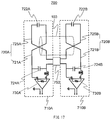
- FIG. 10( a ) illustrates an equivalent circuit of the array coil according to the first embodiment
- FIG. 10 ( b ) illustrates the equivalent circuit looked at a low-impedance circuit side of the first subcoil side
- FIG. 10( c ) illustrates the equivalent circuit looked at the low-impedance circuit side of the second subcoil side;
- FIGS. 11( a ) and 11( b ) illustrate operations of a general parallel resonant circuit
- FIG. 12( a ) shows a result of imaging by a conventional array coil (comparative example)
- FIG. 12( b ) shows a result of imaging by the array coil (example 1) according to the first embodiment
- FIG. 12( c ) is a graph showing sensitivity profiles of the embodiment and the comparative example;
- FIG. 13 is a graph showing a relationship between a current ratio of sub-current and noise correlations
- FIG. 14( a ) illustrates an equivalent circuit of the array coil according to a second embodiment
- FIG. 14( b ) illustrates the equivalent circuit looked at a low-impedance circuit side of the first subcoil side
- FIG. 14( c ) illustrates the equivalent circuit looked at the low-impedance circuit side of the second subcoil side;
- FIG. 15 illustrates a modification example of an electromagnetic coupler
- FIG. 16 is a schematic view showing another modification example of the electromagnetic coupler
- FIG. 17 is a schematic view showing a modification example of a loop coil unit
- FIG. 18 schematically illustrates the array coil according to a third embodiment
- FIG. 19 illustrates a modification example of the array coil according to the third embodiment.
- FIG. 20 illustrates another modification example of the array coil according to the third embodiment.
- the MRI apparatus of the present embodiments features that a specific multichannel RF coil is employed as a receiver RF coil.
- FIG. 1 is an external view of the MRI apparatus of the present embodiment.
- FIG. 1( a ) illustrates the MRI apparatus 100 of a horizontal magnetic field system that uses a tunnel-type magnet for generating a static magnetic field by a solenoid coil.
- FIG. 1( b ) illustrates the MRI apparatus 101 of a hamburger-type (open-type) vertical magnetic field system in which the magnets 111 are separated vertically so as to enhance a sense of openness.
- Each of these MRI apparatuses 100 and 101 are provided with a table 102 for placing an examinee (subject) 103 thereon.
- the subject 103 placed on the table is put in the space for examination where homogeneous magnetic field (static magnetic field) is generated by magnet 110 or 111 .
- the magnet 110 or 111 constitutes a static magnetic field former that forms the static magnetic field.
- the present embodiments are applicable to any of the MRI apparatus 100 of the horizontal magnetic field system and the MRI apparatus 101 of the vertical magnetic field system.
- the types of the MRI apparatus as shown in FIG. 1 are just examples, and any publicly-known various MRI apparatuses may be used for the present invention, regardless of modes or types of the apparatus.
- the coordinate system 090 will be employed, where a direction of the static magnetic field is indicated as z-direction, and two directions orthogonal thereto are indicated as x-direction and y-direction, respectively. In the following, this is similarly applied to all the figures in association with the present specification.
- FIG. 2 is a block diagram showing the schematic configuration of the MRI apparatus.
- the MRI apparatus 100 is provided with the magnet 110 of the horizontal magnetic field system, a gradient magnetic field coil 131 , a transmit RF coil 151 , a receiver RF coil 161 , a gradient magnetic field power source 132 , a shim coil 121 , a shim power source 122 , an RF magnetic field generator 152 , a receiver 162 , a magnetic coupling prevention circuit driver 180 , a computer (PC) 170 , a sequencer 140 , and a monitor 171 .
- the reference numeral 102 represents the table for placing the subject 103 thereon.
- the gradient magnetic field coil 131 is connected to the gradient magnetic field power source 132 , and generates a gradient magnetic field.
- the gradient magnetic field coil 131 and the gradient magnetic field power source 132 constitute a gradient magnetic field former that forms the gradient magnetic field.
- the shim coil 121 is connected to the shim power source 122 , and controls a degree of homogeneity in the magnetic field.
- the transmit RF coil 151 is connected to an RF magnetic field generator 152 , and applies (transmits) an RF magnetic field to the subject 103 .
- the receiver RF coil 161 is connected to the receiver 162 , and receives nuclear magnetic resonance signals from the subject 103 .
- the magnetic coupling prevention circuit driver 180 is connected to a magnetic coupling prevention circuit (described below).
- the magnetic coupling prevention circuit being connected to each of the transmit RF coil 151 and the receiver RF coil 161 , is a circuit for preventing magnetic coupling between the transmit RF coil 151 and the receiver RF coil 161 .
- the sequencer 140 sends commands, respectively to the gradient magnetic field power source 132 , to the RF magnetic field generator 152 , and to the magnetic coupling prevention circuit driver, so as to operate those units.
- the commands are transmitted according to instructions from the computer (PC) 170 .
- a magnetic resonance frequency is set as a reference of detection at the receiver 162 .
- the RF magnetic field is applied to the subject 103 via the transmit RF coil 151 .
- nuclear magnetic resonance signals are generated from the subject 103 .
- the receiver RF coil 161 detects thus generated nuclear magnetic resonance signals, and detection is performed in the receiver 162 .
- the computer (PC) 170 performs control on the overall operations and various signal processing in the MRI apparatus 100 .
- the computer receives signals detected by the receiver 162 via an A/D converter, and performs signal processing such as image reconstruction (functions of an image reconstructor). Results of the processing above are displayed on the monitor 171 . Detected signals and measuring conditions are stored in a storage medium as necessary.
- the computer allows the sequencer 140 to send out commands so that each unit operates at a timing and strength programmed in advance.
- the sequencer 140 sends commands to the shim power source 122 , allowing the shim coil 121 to adjust the degree of homogeneity in the magnetic field.
- the MRI apparatus of the present embodiment employs two types of RF coil; the transmit RF coil 151 and the receiver RF coil 161 .
- One RF coil may serve as both the transmit RF coil 151 and the receiver RF coil 161 , or independent RF coils may be used respectively. Details of the RF coils will be described in the following, taking as an example that the transmit RF coil 151 and the receiver RF coil 161 are independent RF coils, and the transmit RF coil 151 is a birdcage-like shape RF coil (birdcage RF coil), and the receiver RF coil 161 is a multichannel array coil comprising multiple subcoils.
- FIG. 3 there will be described an arrangement of the birdcage RF coil 300 used as the transmit RF coil 151 and the array coil 400 used as the receiver RF coil 161 , together with describing a connection mode of the birdcage RF coil 300 , the array coil 400 , the RF magnetic field generator 152 , the receiver 162 , and the magnetic coupling prevention circuit driver 180 .
- the birdcage RF coil 300 has an approximately cylindrical outer shape (including an elliptic cylinder or a polygonal column), and this approximate cylinder is placed to be coaxial with the central axis of the magnet 110 (the axis in the Z-direction).
- the subject 103 is placed inside the birdcage RF coil 300 .
- the array coil 400 is arranged in proximity to the subject 103 within the birdcage RF coil 300 .
- the birdcage RF coil 300 is connected to the RF magnetic field generator 152 .
- the array coil 400 is connected to the receiver 162 .
- the birdcage RF coil 300 is provided with a magnetic coupling prevention circuit 210 for preventing magnetic coupling with the array coil 400
- the array coil 400 is provided with a magnetic coupling prevention circuit 220 for preventing magnetic coupling with the birdcage RF coil 300 .
- They are referred to as transmit-receive magnetic coupling prevention circuits.
- Those transmit-receive magnetic coupling prevention circuits enable transmission of the RF magnetic field and reception of the nuclear magnetic resonance signals, without magnetic coupling in the arrangement as described above.
- a resonance frequency is tuned to the resonance frequency (magnetic resonance frequency) of an element targeted for excitation, and the RF magnetic field at this magnetic resonance frequency is applied.
- the resonance frequency is tuned to the magnetic resonance frequency of hydrogen nucleus, allowing hydrogen nucleus to be excited.
- the magnetic resonance frequency of the RF magnetic field to be applied is indicated as f0.
- FIG. 4( a ) is a block diagram illustrating a configuration of the birdcage RF coil 300 according to the present embodiments.
- the birdcage RF coil 300 of the present embodiment comprises multiple linear conductors 301 , end conductors 302 for connecting the ends of each of the linear conductors 301 , and capacitors 303 inserted in the end conductors 302 .
- the birdcage RF coil 300 is provided with two input ports 311 and 312 . It is configured such that transmitted signals, 90 degrees out of phase with each other, are inputted into the first input port 311 and into the second input port 312 , respectively, allowing the RF magnetic field to be efficiently applied to the subject 103 .
- the transmit-receive magnetic coupling prevention circuits 210 for preventing magnetic coupling with the receiver RF coil 161 are inserted, respectively in series with the linear conductors 301 of the birdcage RF coil 300 .
- the transmit-receive magnetic coupling prevention circuit 210 may comprise a PIN diode 211 inserted in series with the linear conductor 301 , and control signal lines 212 are connected respectively to both ends of the PIN diode.
- the control signal lines 212 are connected to the magnetic coupling prevention circuit driver 180 .
- a choke coil (not illustrated) may be inserted into the control signal line 212 , so as to avoid mixture of high frequencies.
- the PIN diode 211 possesses properties that it normally indicates high resistance (OFF), and when a value of direct current flowing in the forward direction of the PIN diode 211 becomes a certain amount or more, it mostly indicates conductive (ON). In the present embodiment, such properties are utilized to control ON/OFF of the PIN diode 211 , according to the direct current outputted from the magnetic coupling prevention circuit driver 180 . In other words, when RF signals are transmitted, control current is made to flow to render the PIN diode 211 to be conductive via the control signal lines 212 , whereby the birdcage RF coil 300 functions as the transmit RF coil 151 . On the other hand, when nuclear magnetic resonance signals are received, the control current is suspended, whereby the birdcage RF coil 300 becomes high impedance, and changed to an open state.
- controlling of the direct current (control current) from the magnetic coupling prevention circuit driver 180 allows the birdcage RF coil 300 to function as the transmit RF coil 151 upon transmitting RF signals, whereas upon receiving nuclear magnetic resonance signals, the birdcage RF coil is changed to the open state, thereby removing magnetic coupling with the array coil 400 that serves as the receiver RF coil 161 .
- the array coil 400 used as the receiver RF coil 161 of the present embodiment For ease of explanation, an array coil where two loop-shaped RF coils (surface coils) are placed side by side will be described as an example. However, any multichannel RF coil with an arrangement of multiple subcoils is applicable as the receiver RF coil of the present embodiment, and the number of subcoils is not limited to a particular number.
- the array coil 400 of the present embodiment comprises two subcoils 410 .
- the two subcoils 410 constituting the array coil 400 are referred to as a first subcoil 410 A and the second subcoil 410 B, respectively. If there is no need to particularly identify each of the subcoils 410 as components of the array coil 400 , the alphabet attached to the end of the reference numerals may be omitted (the same shall apply hereafter).
- the first subcoil 410 A and the second subcoil 410 B are surface coils, each having a loop structured on an approximate plane, and there is provided a means (an electromagnetic coupler) 450 therebetween for coupling the two subcoils, electrically, magnetically, or electromagnetically. Functions and details of the electromagnetic coupler 450 will be described later.
- Each of the two subcoils 410 A and 410 B is adjusted to be able to receive nuclear magnetic resonance signals from elements that can be excited by the birdcage RF coil 300 , and each subcoil functions as one channel. Signals received by the first subcoils 410 A and 410 B respectively are transferred to the receiver 162 .
- the first subcoil 410 A comprises a loop coil unit 420 (a first loop coil unit 420 A) for detecting nuclear magnetic resonance signals (RF magnetic field), a low-input impedance signal processing circuit 430 (a first low-input impedance signal processing circuit 430 A), and an electromagnetic coupling adjuster 441 (a first electromagnetic coupling adjuster 441 A) for connecting the loop coil unit 420 with the low-input impedance signal processing circuit 430 , and the first subcoil 410 A is connected to the receiver 162 via the low-input impedance signal processing circuit 430 .
- the electromagnetic coupling adjuster 441 may comprise at least either of a capacitor and an inductor.
- a loop section of the first loop coil unit 420 A (the first loop 421 A) is formed of conductor. Then, the first loop coil unit 420 A is provided with a capacitor 424 A that is inserted in series with an inductor component of the first loop 421 A. This inductor component and the capacitor 424 A constitute a parallel resonant circuit. In order to distinguish the capacitor 424 A from other capacitors, it is referred to as a parallel capacitor 424 (a first parallel capacitor 424 A).
- a capacitor 422 A for adjusting a resonance frequency and the transmit-receive magnetic coupling prevention circuit 220 are inserted in series with the first loop 421 A.
- a series capacitor 422 (a first series capacitor 422 A).
- first series capacitor 422 A there will be described an example where two first series capacitors ( 422 A) are provided, but any number at least one may be applicable as the number of the first series capacitors.
- the first subcoil 410 A is provided with, as circuit components for adjustment, the first electromagnetic coupling adjuster 441 A, the first series capacitors 422 A inserted in series with the inductor component of the first loop 421 A, and the first parallel capacitor 424 A that is inserted in series with the inductor component, rendering the first loop coil unit 420 A to serve as the parallel resonant circuit.
- the second subcoil 410 B is provided with, as circuit components for adjustment, a second electromagnetic coupling adjuster 441 B, a second series capacitors 422 B inserted in series with the inductor component of a second loop 421 B, and a second parallel capacitor 424 B that is inserted in series with the inductor component, rendering the second loop coil unit 420 B to serve as the parallel resonant circuit.
- One terminal of the low-input impedance signal processing circuit 430 is connected to one end of the parallel capacitor 424 of the loop coil unit 420 via the electromagnetic coupling adjuster 441 .
- the other terminal of the low-input impedance signal processing circuit 430 is connected directly to the other end of the parallel capacitor 424 of the loop coil unit 420 .
- the transmit-receive magnetic coupling prevention circuit 220 removes magnetic coupling with the birdcage RF coil 300 being the transmit RF coil 151 .
- the transmit-receive magnetic coupling prevention circuit 220 may comprise a capacitor 423 that is inserted in series with the conductor constituting the loop 421 , the PIN diode 221 connected in parallel with the capacitor 423 , and the inductor 222 .
- Control signal lines 223 may be connected to both ends of the PIN diode 221 .
- the control signal lines 223 may be connected to the magnetic coupling prevention circuit driver 180 .
- a choke coil (not illustrated) may be inserted into the control signal line 223 , so as to avoid mixture of high frequencies.
- the inductor 222 and the capacitor 423 are adjusted so that they resonate in parallel at a frequency of the received nuclear magnetic resonance signals.
- the parallel resonant circuit has characteristics of becoming high impedance (high resistance) at the resonance frequency. Therefore, when the current passes through the PIN diode 221 , the PIN diode 221 is turned on, and the capacitor 423 of the loop 421 becomes resonant in parallel with the inductor 222 at the frequency of the received nuclear magnetic resonance signals, resulting in that the capacitor 423 becomes high impedance. Therefore, at the frequency of thus received nuclear magnetic resonance signals, a part of the loop coil unit 420 becomes high impedance, turned to be in an open state, and then, the subcoil 410 having the loop coil unit 420 is also turned to be in the open state.
- FIG. 5( a ) illustrates as an example, one transmit-receive magnetic coupling prevention circuit 220 is inserted into the subcoil 410 , but the number of the transmit-receive magnetic coupling prevention circuits 220 to be inserted into the subcoil 410 is not limited to one. Two or more transmit-receive magnetic coupling prevention circuits may be inserted into each of the loops 421 . By inserting a plurality of the transmit-receive magnetic coupling prevention circuits, the magnetic coupling between the transmit RF coil 151 and the receiver RF coil 161 can be lowered to a sufficient level.
- the configuration of the transmit-receive magnetic coupling prevention circuit 220 is not limited to the above-mentioned configuration.
- a cross diode 221 m may be employed instead of the PIN diode 221 .
- the cross diode 221 m is turned on, and the capacitor 423 of the loop 421 and the inductor 222 realize parallel resonance at the frequency of the received nuclear magnetic resonance signals, and then high impedance occurs.
- the magnetic coupling prevention circuit driver 180 is not necessary.
- values of the inductance and capacitance of the circuit components for adjustment included in each of the subcoils 410 A and 410 B, and values of the inductance and capacitance provided by the electromagnetic coupler 450 are adjusted, whereby each of the subcoils 410 A and 410 B is adjusted so that they can receive the nuclear magnetic resonance signals, and the electric fields generated between the subcoils intensify each other, according to the current passing through each coil upon receipt of signals by the subcoils.
- the first subcoil 410 A is arranged in a manner that, upon receipt of signals, the first current (induced current) based on the signals detected by first subcoil 410 A passes therethrough, and a part of the first current (the first sub-current) passes through the second subcoil 410 B, in the opposite direction of the current in the first subcoil, thereby intentionally guiding the current to flow in the other coil loop unit.
- the second subcoil is arranged in a manner that, upon receipt of signals, the second current (induced current) based on the signals detected by the second subcoil 410 B passes therethrough, and a part of the second current (the second sub-current) passes through the first subcoil 410 A, in the opposite direction of the current in the second subcoil, thereby intentionally guiding the current to flow in the other coil loop unit.
- Noise generated from each channel of the receiver RF coil in the MRI apparatus is mainly thermal noise, caused by the subject, and it is Gauss type noise detected by electric field coupling between the coils and subject. This type of noise is increased according to the number of channels, when the channels are combined in reconstructing an image. Furthermore, in the array coil, multiple subcoils are placed adjacent to each other, covering the subject, and thus electric field distributions of the subcoils are likely to be analogous to each other. Accordingly, correlation may occur between the detected signals (noise signals). If this correlation (noise correlation) is strong, noise is intensified upon combining images, and an SNR of the composite image is lowered due to the thus intensified noise. Therefore, it is preferable that the noise correlation should be lower.
- the noise correlation ⁇ between the RF coils is obtained according to the following formulas 1 and 2:
- R ij ⁇ ⁇ ⁇ V ⁇ E -> i ⁇ ( x , y , z ) ⁇ E -> j * ⁇ ( x , y , z ) ⁇ dV ( 1 )
- ⁇ ij R ij R ii * ⁇ R jj ( 2 )
- ⁇ electric conductivity of the subject
- V volume of the subject
- Ei the electric field (complex number) generated by the i-th coil
- Ej is the electric field (complex number) generated by the j-th coil.
- E* represents complex conjugate of E.
- the magnitude of noise correlation is determined by volume integral of an inner product of the electric fields that are generated, respectively by the coils within the subject. By reducing the inner product Rij of the electric fields, the noise correlation can be controlled to be low, thereby preventing deterioration of the SNR due to the noise correlation.
- FIG. 6( b ) schematically illustrates an electric field distribution that is generated in the subject 103 , when clockwise current passes through the subcoils 470 A and 470 B in the array coil that is provided with a conventional magnetic coupling elimination means.
- a fine dot pattern indicates a positive electric field
- a coarse dot pattern indicates a negative electric field (the same is applied to FIG. 6( a ) ).
- the electric field distribution (Det: ch1) becomes positive on the right side of the subcoil 470 A in the figure, whereas in the left side of the figure, the electric field distribution becomes negative.
- the electric field distribution in the (Det: ch1) is generated by a part of the current (sub-current) passing though the subcoil 410 B, in addition to the electric field generated by the induced current (the first current) passing through the subcoil 410 A.
- a region surrounded by a narrow rectangular indicates the electric field based on this sub-current.
- the electric field distribution in the (Det: ch2) includes the electric field according to the induced current passing through the subcoil 410 B and the electric field according to the sub-current (a part of the induced current) passing through the subcoil 410 A. Consequently, as shown in the lower row of FIG. 6( a ) , the inner product of the electric fields becomes negative between the two subcoils 410 A and 410 B, whereas it becomes positive on both sides, but smaller relative to FIG. 6( b ) .
- the current path is not limited to this shape.
- a part of the figure-of-eight path may be cut off. It is only required to establish a current configuration where the electric fields generated in a living body by the current passing through the subcoils, intensify each other between the subcoils. This configuration enhances flexibility in design, and sensitivity can be improved in the area of interest.
- Adjustment for generating the part of current (sub-current) in the other subcoil may be performed either in a symmetrical manner or in an unsymmetrical manner. In other words, following adjustments are also applicable; when current flows according to the signals detected by the first subcoil, a part of the current (sub-current) flows into the second subcoil. On the other hand, when current flows according to the signals detected by the second subcoil, no current may pass through the first subcoil, or the amount of current passing through the first subcoil may be different from the amount of the sub-current passing through the second subcoil.
- the array coil comprising two subcoils, but it is further possible to configure such that the array coil comprises three channels or more, and following adjustments are also applicable; at least one subcoil, and two subcoils placed on both sides thereof are provided, and when current passes through the one subcoil, a part of the current passes through the subcoils on both sides, or the part of the current passes through either one of the subcoils on both sides.
- FIG. 7 illustrates a layout example of the array coil 400 of the MRI apparatus according to the present embodiment.
- FIG. 7( a ) illustrates an example that the array coil 400 comprising two subcoils 410 A and 410 B is arranged on a plane approximately vertical to the direction of the static magnetic field (Z direction), and the subcoils are arranged in the Y-direction.
- the array coil 400 may be arranged on a plane at an angle approximately parallel to the direction of static magnetic field.
- FIG. 7( a ) illustrates an example that the array coil 400 comprising two subcoils 410 A and 410 B is arranged on
- the first subcoil 410 A may be arranged on the plane vertical to the static magnetic field, and the second subcoil 410 B may be arranged on the plane parallel to the static magnetic field.
- the array of the subcoils may be oriented in the X-direction. Such modification of the layout angle enables detection or generation of rotating magnetic field that cannot be provided by the subcoil 410 alone, allowing acquisition of magnetic resonance signals with high sensitivity in the area of interest.
- the distance from the two subcoils 410 A and 410 B should be almost equal, in the viewpoint of reduction of noise correlation.
- the subcoils should also be arranged symmetrically with respect to the X-axis. With this configuration, the subject-form dependence of the coil properties may be reduced.
- the symmetry axis is not limited to the X-axis. Any axis (direction) having a property of symmetry with respect to the subject may be applicable.
- An imaging method using the MRI apparatus of the present embodiment is similar to operations of conventional MRI apparatuses.
- RF magnetic field pulses are applied from the transmit RF coil 151 (e.g., the birdcage RF coil 300 ) to the subject 103 that is placed in the static magnetic field space generated by the magnetostatic field magnet 110 , together with applying gradient magnetic field pulses from the gradient magnetic field coil 131 .
- the transmit-receive magnetic coupling prevention circuit 220 is open in the receiver RF coil 161 , to remove magnetic coupling with the receiver RF coil 161 .
- the receiver RF coil 161 (multichannel coil: array coil 400 ) arranged in proximity to the subject 103 receives nuclear magnetic resonance signals that are generated from nuclei of elements constituting living tissues of the subject 103 .
- the transmit-receive magnetic coupling prevention circuit 210 becomes open, so as to remove the magnetic coupling between the transmit RF coil 151 and the receiver RF coil 161 .
- the computer (signal processor) 170 processes MR signals received respectively by the subcoils of the receiver RF coil 161 , and if the imaging method thereof is a high-speed imaging method, such as employing a parallel imaging, for example, the computer creates an image of the subject according to the imaging reconstruction method that follows an algorithm of the parallel imaging. It is also possible to obtain an image by subjecting the signals obtained from respective channels to MAC (multi-array coil) synthesis. In creating the image, sensitivity distribution information of each of the subcoils is utilized as appropriate.
- a multichannel coil having been adjusted in a particular manner is used as the receiver RF coil, whereby noise correlation between the subcoils is reduced, and a high quality image can be obtained.
- the MRI apparatus of the present embodiment comprises the static magnetic field former configured to form a static magnetic field, the gradient magnetic field former configured to form a gradient magnetic field, the transmit RF coil configured to irradiate a subject placed in the static magnetic field, with an RF magnetic field, the receiver RF coil configured to detect nuclear magnetic resonance signals from the subject, and the signal processor configured to process the nuclear magnetic resonance signals detected by the receiver RF coil.
- the receiver RF coil comprises a first subsoil having a first loop coil unit made of a conductor, being capable of receiving nuclear magnetic resonance signals from the subject, a second subsoil having a second loop coil unit made of a conductor, being capable of receiving nuclear magnetic resonance signals from the subject, and an electromagnetic coupler placed between the first subcoil and the second subcoil, for coupling the first subcoil and the second subcoil electromagnetically, wherein adjustments are made in a manner that a part of the first current passing through the first loop coil unit according to signals detected by the first loop coil unit, is made to flow into the second loop coil unit in the form of the first sub-current, and an electric field generated in the subject by the first current and an electric field generated in the subject by the first sub-current intensify each other in the space between the first loop coil unit and the second loop coil unit.
- At least one of the first subcoil and the second subcoil further comprises a magnetic coupling adjuster connecting the loop coil unit of the subcoil with a low-impedance signal processing circuit that is connected to the subcoil
- the magnetic coupling adjuster further comprises at least either of a capacitor and an inductor as an adjusting circuit component
- the loop coil unit comprises a series capacitor that is inserted in series with an inductor component thereof, and a parallel capacitor inserted in series with the inductor component to render the loop coil unit to serve as a parallel resonant circuit
- adjustment of at least one of the subcoils is performed by adjusting values of the adjusting circuit component, the series capacitor, and the parallel capacitor.
- the array coil 400 of the present embodiment which is arranged and adjusted as described above, is tuned to the magnetic resonance frequency f0.
- signals detected by the first loop coil unit 420 A pass through the second subcoil 410 B, thus forming current that flows in a figure-of-eight path, and the electric fields generated between the loops intensify each other.
- noise correlation between the first subcoil 410 A and the second subcoil 410 B is lowered, and accordingly, the SNR of a composite image can be increased.
- the array coil 400 of the present embodiment low noise can be achieved in the form of multichannel.
- adjustments of the arrangement and values of the circuit components enable implementation of such multichannel and low noise. Therefore, this may prevent increase in complexity of the configuration.
- the MRI apparatus of the present embodiment is allowed to obtain a high-quality image targeted to a wide region.
- the MRI apparatus of the present invention features in using the receiver RF coil, particularly adjusted, and the configuration other than this feature may be modified variously.
- some of the components that are shown in FIG. 2 may be excluded, or any component not shown in FIG. 2 may be added.
- FIG. 8 illustrates an arrangement example where the multichannel array coil is employed in the MRI apparatus 101 of the vertical magnetic field system.
- FIG. 8( a ) illustrates an example where two subcoils 410 constituting the array coil 400 are arranged on a plane approximately vertical to the direction of the static magnetic field
- FIG. 8( b ) illustrates an example where one of the subcoils is placed on the plane vertical to the direction of the static magnetic field, and the other subcoil is placed on a plane parallel to the direction of the static magnetic field.
- FIG. 8( c ) illustrates an example where a multichannel array coil 800 using multiple surface coils 810 is placed.
- the RF coil of the present invention is a multichannel RF coil that is used as the receiver RF coil of the MRI apparatus, and it is provided with multiple subcoils.
- Each of the multiple subcoils is capable of receiving nuclear magnetic resonance signals generated in the MRI apparatus, and those subcoils are adjusted so that electric fields generated within the subject by the current passing through each of the subcoils intensify each other between adjacent subcoils.
- the array coil ( FIG. 5 ) used as the receiver RF coil as described in the foregoing embodiment of the MRI apparatus is one of the embodiments of the RF coil according to the present invention. Operations ( FIG. 6 ) and modification examples as described in the foregoing embodiment may be commonly applied to each of the following embodiments described below.
- the RF coil of the present embodiment has a configuration similar to the configuration of the array coil 400 as shown in FIG. 5 , comprising two subcoils; the first subcoil 410 A and the second subcoil 410 B, and further comprising an electromagnetic coupler 450 between the subcoils 410 A and 410 B.
- the RF coil is adjusted in a manner that a part of the current (sub-current) detected by the first subcoil 410 A passes through the second subcoil 410 B upon receipt of signals by the first subcoil 410 A, and simultaneously, a part of the current (sub-current) detected by the second subcoil 410 B passes through the first subcoil 410 A upon receipt of signals by the second subcoil 410 B.
- the amount of the sub-current can be adjusted by circuit components provided for the adjustment, being inserted in or connected with the subcoil.
- the sub-current preferably corresponds to 5% to 30% of the current that is detected by the first subcoil or the second subcoil.
- the first subcoil 410 A and the second subcoil 410 B may be placed approximately on the same plane.
- “approximately on the same plane” indicates a relationship that adjacent coil elements are placed approximately on the same plane, and a region other than the coil elements (end portions other than the coil elements) may be bent or curved. It is also possible that the first subcoil 410 A and the second subcoil 410 B are placed in a manner that the coil elements partially overlap one on another.
- the RF coil of the present embodiment will be described in detail.
- the vertical direction on the figure represents X-axis direction
- the horizontal direction on the figure represents Y-axis direction
- the direction orthogonal to the paper plane represents Z-axis direction.
- the alphabets attached to the end of the reference numerals may be omitted.
- the first subcoil 410 A and the second subcoil 410 B are placed in a manner that a plane formed by the loop 421 of the loop coil unit 420 in each subcoil becomes relatively close to a plane that is vertical to the magnetic field direction (Z axis direction).
- the loop 421 of the loop coil unit 420 may have any shape, such as the rectangle as illustrated, a polygonal, and a circular shape (including an oval shape).
- the electromagnetic coupler 450 between the two subcoils 410 A and 410 B includes an inductor 451 A on the first subcoil 410 A side and an inductor 451 B on the second subcoil 410 B side, and the two subcoils 410 A and 410 B are coupled according to magnetic coupling.
- the array coil of the present embodiment employs low-input impedance signal amplifiers 431 A and 431 B, respectively as the first low-impedance signal processing circuit 430 A and the second low-impedance signal processing circuit 430 B.
- the low-input impedance signal amplifier 431 By using the low-input impedance signal amplifier 431 , signals detected by the loop coil unit 420 can be amplified immediately, and thus data with less noise can be acquired.
- a magnitude of input impedance of the low-input impedance signal amplifier 431 is not limited, but it may be approximately equal to or less than 2 ⁇ . It should be noted that the low-impedance signal processing circuit 430 is not restricted to the low-impedance signal amplifier 431 .
- the series capacitors 422 , the transmit-receive magnetic coupling prevention circuit 220 (including the capacitor 423 ), and the parallel capacitor 424 , which are inserted in each loop coil unit 420 , are configured the same as those in the array coil illustrated in FIG. 5 . Also in the present embodiment, three capacitors (such as 422 and 424 ) are inserted in the loop 421 of the loop coil unit 420 , but the number of the capacitors is not limited to this example. It is sufficient if at least one capacitor is inserted.
- an inductor (referred to as an adjustment inductor, for the purpose of distinguishing from other inductors) is used as the electromagnetic coupling adjuster 441 , but the inductor is not necessarily used as the electromagnetic coupling adjuster 441 .
- the parallel capacitor 424 is connected to the electromagnetic coupling adjuster 441 via a conductor. Since the conductor contains an inductor component, even without additional inductor, the parallel capacitor 424 , the electromagnetic coupling adjuster 441 , and the inductor component contained in the conductor connecting therebetween may form a parallel resonant circuit.
- a capacitor may also serve as the electromagnetic coupling adjuster 441 .
- a parallel circuit of the capacitor and the inductor may also serve as the electromagnetic coupling adjuster 441 .
- the first subcoil 410 A and the second subcoil 410 B of the array coil 400 implement the aforementioned functions, by adjusting values of the inductor 451 A and the inductor 451 B constituting the electromagnetic coupler 450 , the first electromagnetic coupling adjuster 441 A, the second electromagnetic coupling adjuster 441 B, the first series capacitors 422 A, the second series capacitors 422 B, the first parallel capacitor 424 A, and the second parallel capacitor 424 B.
- FIG. 10( a ) illustrates the equivalent circuit 600 of the array coil 400 according to the present embodiment.
- the number value in the hundreds digit of the reference numeral representing each component as shown in FIG. 9 is altered from “4” to “6”, to indicate the corresponding component in FIG. 10 .
- the inductor is 641 in FIG. 10 corresponds to the inductor 441 in FIG. 9
- the series capacitor 622 in FIG. 10 corresponds to the capacitor 422 in FIG. 9 .
- the capacitor 622 A corresponds to a combination of two of the first series capacitors 422 A
- the capacitor 622 B corresponds to a combination of two of the second series capacitors 422 B
- the inductor 621 A indicates the inductor component of the first loop 421 A
- the inductor 621 B indicates the inductor component of the second loop 421 B.
- values of the inductors and the capacitors being the components are represented by the reference symbols L and C, respectively, each with a subscript, shown in proximity to the respective components.
- the value Z11 of the impedance 632 A corresponds to a value of the input impedance of the low-input impedance signal amplifier 431 A used as the first low-impedance signal processing circuit 430 A.
- the value Z21 of the impedance 632 B corresponds to a value of the input impedance of the low-input impedance signal amplifier 431 B used as the second low-impedance signal processing circuit 430 B.
- Those impedance values Z11 and Z21 are sufficiently low, and therefore, they shall be considered as 0 ⁇ (short circuits) in the following.
- FIGS. 10( b ) and 10( c ) illustrate the equivalent circuits showing the state that the first subcoil and the second subcoil as shown in FIG. 10( a ) are coupled via the electromagnetic coupler 450 .
- the equivalent circuit 601 as shown in FIG. 10( b ) indicates the equivalent circuit of the first subcoil 410 A (the first resonator), excluding the low-impedance signal processing circuit 430 A ( 631 A), in the state where the current of the first loop coil unit 420 A passes through the second loop coil unit 420 B, when looked at the first low-impedance signal processing circuit 430 A ( 631 A).
- the equivalent circuit 602 as shown in FIG.
- 10( c ) indicates the equivalent circuit of the second subcoil 410 B (the second resonator), excluding the low-impedance signal processing circuit 430 B ( 631 B), in the state where the current of the second loop coil unit 420 B passes through the first loop coil unit 420 A, when looked at the second low-impedance signal processing circuit 430 B ( 631 B).
- the inductor 451 A of the electromagnetic coupler 450 for the first loop coil unit 420 A, and the inductor 451 B of the electromagnetic coupler 450 for the second loop coil unit 420 B are collectively referred to as a mutual inductance 650
- M represents a value of the mutual inductance 650
- the magnetic coupling coefficient k is a value between or equal to 0 and 1.
- L11 indicates the magnitude of the inductor 451 A of the first subcoil 410 A
- L21 indicates the magnitude of the inductor 451 B.
- the mutual inductance M is determined by the magnitude of the inductors, and the magnetic coupling coefficient.
- Variation of the distance between the inductors 451 B and 451 A enables adjustment of the amount of electromagnetic coupling. Therefore, controlling the magnitude of the inductors and the distance between the subcoils allows adjustment of the amount of the sub-current (a part of the current detected by one subcoil and passing through the other subcoil).
- the inductor component of the first loop coil unit 420 A and the inductor component of the second loop coil unit 420 B there may also be mutual inductance according to the inductor component of the first loop coil unit 420 A and the inductor component of the second loop coil unit 420 B.
- all those inductor components shall be included within the mutual inductance between the inductor 451 A and the inductor 451 B.
- a resonance frequency of the series resonant circuit only comprising the parallel capacitor 424 A, the adjustment inductor 441 A, and the first low-impedance signal processing circuit 430 A is represented by f10.
- a resonance frequency of the series resonant circuit only comprising the parallel capacitor 424 B, the adjustment inductor 441 B, and the second low-impedance signal processing circuit 430 B is indicated as f20. Further as shown in FIG.
- the resonance frequency of the resonator of the first subcoil 410 A (the first resonator) is indicated as f11, when looked at the first low-impedance signal processing circuit 430 A ( 631 A).
- the resonance frequency of the resonator of the second subcoil 410 B (the second resonator) is indicated as f21, when looked at the second low-impedance signal processing circuit 430 B ( 631 B).
- the frequency of the nuclear magnetic resonance signal to be detected (the nuclear magnetic resonance frequency) is indicated as f0.
- Each of the circuit components of the array coil 400 according to the present embodiment is adjusted so that each of the aforementioned resonance frequencies satisfies the following formulas 4 to 8.
- both ends of the capacitor 424 A of the first subcoil 410 A do not become highly resistant upon receiving signals. Therefore, this facilitates flowing of the current from the second subcoil 410 B into the first subcoil 410 A.
- both ends of the capacitor 424 B of the second subcoil 410 B do not become highly resistant upon receiving signals. Therefore, this facilitates flowing of the current from the first subcoil 410 A into the second subcoil 410 B.
- the first resonator of the first subcoil 410 A becomes the circuit 601 where the inductor component (L10) of the first loop 421 A and the inductor component (L20) of the second loop 421 B allow current to flow via the inductors 451 A and 451 B of the magnetic coupler 450 .
- the value of the inductor 626 A and the value of the inductor 626 B are equal to the values obtained by subtracting the value M of the mutual inductance, respectively from the values L11 and L21 of the inductors 651 A (inductor 451 A) and 651 B ( 451 B).
- each of the circuit components is adjusted so that magnetic coupling (a function of the magnetic coupler 450 ) allows for example, circulating current I 1 in a clockwise direction to pass through the first loop 421 A, and circulating current I 2 in a counterclockwise direction to pass through the second loop 421 B, resulting in that a current path having a figure-of-eight shape is formed effectively by the loop 421 A and the loop 421 B, and current passes therethrough.
- the coils are tuned to the magnetic resonance signals, and nuclear magnetic resonance signals can be detected.
- the second resonator of the second subcoil 410 B upon receiving signals, becomes the circuit 602 where the inductor component (L20) of the second loop 421 B and the inductor component (L10) of the first loop 421 A allow current to flow via the inductors 451 A and 451 B of the magnetic coupler 450 .
- each of the circuit components is adjusted so that magnetic coupling allows, for example, circulating current I 4 in a counterclockwise direction to pass through the first loop 421 A, and circulating current I 3 in a clockwise direction to pass through the second loop 421 B, resulting in that a current path having a figure-of-eight shape is formed effectively by the loop 421 A and the loop 421 B, and current passes therethrough.
- the coils are tuned to the magnetic resonance signals, and nuclear magnetic resonance signals can be detected.
- each of the subcoils 410 is allowed to receive the nuclear magnetic resonance signals from the subject as a detection target.
- Forming of the current path as described above may generate the electric fields as shown in FIG. 6( a ) , whereby noise correlation is reduced.
- a part of the current in one coil is made to flow in the other coil, and thus it is possible to provide various sensitivity distributions for a region to be imaged. Therefore, this allows those coils to function as a multichannel coil.
- the shape of the loop is rectangle, and the diameter of each of the loops 421 A and 421 B is set to be 100 mm, respectively for the first loop coil unit 420 A and the second loop coil unit 420 B.
- the distance between the centers of the two subcoils 410 is set to be 140 mm.
- each of the circuit components of the second subcoil 410 B is adjusted.
- Values of the capacitance C21 of the series capacitor 622 B and the capacitance C24 of the parallel capacitor 624 B are adjusted.
- those values are adjusted so that the equivalent circuit 602 as shown in FIG. 10( c ) could resonate at 64 MHz, and impedance across the series circuit of the adjustment inductor 641 B and the parallel capacitor 624 B should become 50 ⁇ .
- the value L22 of the adjustment inductor 641 B and the value C24 of the parallel capacitor 624 B are adjusted so that the formula 8 is satisfied.
- the values of L22 and C24 are determined so that the parallel resonant circuit (referred to as L22C24 resonant circuit) made up of the adjustment inductor 641 B and the parallel capacitor 624 B, could operate as a capacitor.
- L22C24 resonant circuit the parallel resonant circuit made up of the adjustment inductor 641 B and the parallel capacitor 624 B.
- Those values are adjusted on the basis of a principle of the parallel resonant circuit characteristic. The principle of the parallel resonant circuit characteristic will be described later.
- those values are adjusted so that the resonance frequency (f10) of the L22C24 resonant circuit could be a value smaller than f0.
- 51 MHz is used as the value smaller than f0, which is 20% lower.
- each of the circuit components in the first subcoil 410 A is adjusted. It is assumed that at this stage, the circuit components in the second subcoil 410 B have already been adjusted as described above.
- the value C11 of the series capacitor 622 A and the value C14 of the parallel capacitor 624 A are adjusted so that the equivalent circuit 601 as shown in FIG. 10( b ) could resonate at 64 MHz, and the impedance at the both ends of the series circuit of the inductor 641 A and the parallel capacitor 624 A (C14) should become 50 ⁇ .
- the value L12 of the adjustment inductor 641 A and the value C14 of the parallel capacitor 624 A are adjusted in a manner that the formula 7 is satisfied, so that the second subcoil 410 B could be electromagnetically coupled with the first subcoil 410 A.
- the values of L12 and C14 are determined so that the parallel resonant circuit (L12C14 resonant circuit) made up of the adjustment inductor 641 A and the parallel capacitor 624 A could operate as a capacitor.
- Those values are adjusted on the basis of a principle of the parallel resonant circuit characteristic. The principle of the parallel resonant circuit characteristic will be described later.
- those values are adjusted so that the resonance frequency (f20) of the L12C14 resonant circuit could become a value smaller than f0.
- f0 resonance frequency
- 51 MHz is used as the value smaller than f0, which is 20% lower.
- a coupling amount of electromagnetic coupling is adjusted by varying the distance between the inductors 451 B and 451 A of the magnetic coupler 450 .
- the values of both the inductors 451 B and 451 A are set to 50 nH.
- Such adjustments of the first subcoil 410 A and the second subcoil 410 B may be repeated several times as required.
- the array coil 400 of the present embodiment resonates at the frequency of the nuclear magnetic resonance, and receives nuclear magnetic resonance signals.
- two subcoils 410 A and 410 B form the current flow having the figure-of-eight shape.
- the electric fields generated between the subcoils are adjusted so that they intensify each other.
- Noise correlation is obtained by the inner product of those electric fields. Therefore, when the inner product is obtained in each region, as shown in the lower part of FIG. 6( a ) , in the present embodiment, the region between the coils indicates a large negative value relative to the other regions.
- the noise correlation is obtained by the inner product, it indicates a negative value with respect to the conventional method as shown in FIG. 6( b ) . Consequently, this means that the noise correlation becomes smaller than the conventional method.
- the L12C14 resonant circuit and the L22C24 resonant circuit are allowed to operate like capacitors, and the first subcoil 410 A and the second subcoil 410 B operate being tuned to each other. Therefore, the sensitivity region is enlarged with higher sensitivity, and consequently, the SNR of the composite image can be improved.
- FIG. 11( a ) and FIG. 11( b ) illustrate an operation of the parallel resonant circuit.
- the inductor 502 (L) and the capacitor 501 (C) are connected in parallel.
- the impedance Z varies depending on the frequency f being applied, and resonance occurs at a predetermined frequency (referred to as the resonance frequency fR).
- the impedance Z at the both ends of the parallel resonant circuit 500 is maximized at the frequency fR.
- the impedance Z is expressed by the formula 10 at a frequency lower than the resonance frequency fR of the parallel resonant circuit 500 (f ⁇ fR), and the parallel resonant circuit 500 operates as an inductive reactance (inductor).
- the impedance Z is expressed by the formula 12 at a frequency higher than the resonance frequency fR of the parallel resonant circuit 500 (f>fR), and the parallel resonant circuit 500 operates as a capacitive reactance (capacitor).
- the parallel resonant circuit 500 operates differently in accordance with the frequency f of the applied voltage, with a boundary of its resonance frequency fR.
- the value of the resonance frequency, the values of L12 and C14, and the values of L22 and C24 are determined, so that the L12C14 resonant circuit and the L22C24 resonant circuit could operate as the capacitor.
- FIG. 12( b ) is a result of imaging according to the present embodiment. Noise correlations were 0.15 and 0.01, respectively.
- FIG. 12( c ) illustrates a sensitivity profile on the Z-axis after sensitivities of the two subcoils are combined.
- the solid line indicates the profile of the present embodiment and the broken line indicates the profile of the conventional RF coil (comparative example) where the magnetic coupling has been removed.
- the resonance frequency of the parallel resonant circuit (L22C24 resonant circuit) made up of the adjustment inductor 641 B (L22) and the parallel capacitor 624 B (C24) was adjusted to 51 MHz, which was smaller value than f0.
- the array coil 400 of the present embodiment configuring a current distribution having a shape like figure-of-eight by electromagnetic coupling, the noise correlation was reduced and the SNR of the resultant composite image was improved.
- both the L12C14 resonant circuit and the L22C24 resonant circuit were set to be the value lower than f0 by 20%, but the value is not limited to this value. It is only required to generate current having the figure-of-eight shape, so as to achieve adjustments for reducing the noise correlation.
- the resonance frequency of the L12C14 resonant circuit may be different from the resonance frequency of the L22C24 resonant circuit. Such difference in resonance frequencies may allow deriving of an optimum SNR that is suitable for the shape of the coils.
- 51 MHz was used as a value lower than f0 (64 MHz) for the adjustments of the resonance frequency of the L22C24 resonant circuit, but any other values may be applicable as the resonance frequency of the L22C24 resonant circuit.
- Adjustment of this value allows adjustment of a phase difference between the first current passing through the first loop coil unit 420 A, and the second current passing through the second loop coil unit 420 B.
- the current phase difference ⁇ becomes ⁇ /2 ⁇ 3 ⁇ /2, current having the figure-of-eight shape can be generated.
- the amount of the sub-current (the current ratio) was adjusted to 10%.
- the amount of the sub-current should allow the noise correlation to change to any value enabling enhancement of the SNR in a targeted imaging area, and thus the amount of the sub-current may be adjusted appropriately, in accordance with the distance between coils or other conditions.
- FIG. 13 is a graph showing the relationship between the noise correlation and the current. The solid line indicates the relationship when the distance between coils (distance between the centers of the loop sections of the subcoils) is 140 mm (Example 1), and the dotted line indicates the relationship when the distance is 110 mm.
- the noise correlation becomes 0.2 according to the conventional method, where the current ratio is adjusted to be 0%.
- the current ratio is 10%
- the noise correlation becomes zero.
- the noise correlation becomes 0.4.
- the noise correlation is reduced, and when the current ratio is 20%, the noise correlation becomes zero.
- it is desirable that the amount of the sub-current passing through the other subcoil should fall into the range from 5 to 30% of the current that is detected by one subcoil.
- the amount of the first sub-current (sub-current passing through the subcoil 410 A) may be equal to or different from that of the second sub-current (sub-current passing through the subcoil 410 B). Such difference may allow deriving of an optimum SNR that is suitable for the shape of the coils.
- the noise correlation may vary depending on the shape and the size of the subject and the arrangement of coils, it is preferable to define the position and arrangement of coils and to adjust the values, considering the shape of the subject to some extent.
- the RF coil (array coil) of the present embodiment is adjusted in a manner that a part of the first current passing through the first loop coil unit according to the signals detected by the first loop coil, flows into the second loop coil unit as the first sub-current, and an electric field generated by the first current within the subject, and an electric field generated by the first sub-current within the subject intensify each other in the space between the first loop coil unit and the second loop coil unit.
- the RF coil is also adjusted in a manner that a part of the second current passing through the second loop coil unit according to the signals detected by the second loop coil, flows into the first loop coil unit as the second sub-current, and an electric field generated by the second current within the subject, and an electric field generated by the second sub-current within the subject intensify each other in the space between the first loop coil unit and the second loop coil unit.
- noise correlation between the subcoils can be reduced.
- the first subcoil 410 A and the second subcoil 410 B can operate, being tuned to each other, whereby the sensitivity region is enlarged, allowing acquisition of high sensitivity. Consequently, the SNR of the composite image can be improved.
- the first sub-current being a part of the current of the signals detected by the first subcoil 410 A as one of the two subcoils 410 , passes through the second subcoil 410 B, and the second sub-current being a part of the current of the signals detected by the second subcoil 410 B passes through the first subcoil 410 A.
- adjustments are made in a manner that the current detected by the second subcoil 410 B is prevented from flowing into the first subcoil 410 A.
- the configuration of the array coil 400 is the same as that of the first embodiment, but an adjustment method is different in adjusting values of constituent circuit components (the adjustment inductor 441 , the series capacitors 422 , and the parallel capacitor 424 ).
- FIG. 14 the capacitors and values thereof, the inductors and values thereof, and the resonance frequency of each circuit are represented by the same reference numerals as those of the equivalent circuit 600 of the first embodiment as shown in FIG. 10 .
- the circuit components constituting the array coil 400 are adjusted so that the following formulas 14 to 17 are satisfied.
- both ends of the capacitor 424 B of the second subcoil 410 B are prevented from being highly resistant, allowing the second subcoil 410 B to be magnetically coupled with the first subcoil 410 A.
- FIG. 14( b ) illustrates the equivalent circuit 611 of the first subcoil 410 A, in the state that the first loop coil unit 420 A and the second loop coil unit 420 B are magnetically coupled according to the aforementioned adjustment.
- the first loop coil unit 420 A and the second loop coil unit 420 B are magnetically coupled, and according to the signals detected by the first loop coil unit 420 A, current I 1 in a clockwise direction passes through the first loop coil unit 420 A, and simultaneously, a part of the current I 2 passes through the second loop coil unit 420 B in a counterclockwise direction.
- each of the circuit components is adjusted according to the formula 16, whereby both ends of the capacitor 424 A of the first subcoil 410 A become highly resistant, upon receiving signals, and thus the second subcoil 410 B operates independently.
- FIG. 14( c ) illustrates the equivalent circuit 612 of the second resonator of the second subcoil 410 B, when the second loop coil unit 420 B operates independently according to the aforementioned adjustments.
- the second resonator of the second subcoil 410 B corresponds to the circuit 612 of the second loop coil unit 420 B alone. Therefore, the current I 3 that flows according to the second loop coil unit 420 B never passes through the first loop coil unit 420 A.
- each of the circuit components is adjusted according to the formula 14, whereby the resonance frequency f11 of the first resonator and the resonance frequency f22 of the second resonator, upon receiving signals, become equal to the nuclear magnetic resonance frequency f0. This allows the subcoil 410 A and the subcoil 410 B to detect the nuclear magnetic resonance signals.
- each of the circuit components is adjusted, setting the magnetic resonance frequency f0 to 64 MHz that corresponds to the nuclear magnetic resonance frequency of hydrogen in the static magnetic field strength of 1.5 T (tesla), in the array coil according to the second embodiment.
- the shape and the size of the coil are the same as those of example 1 in the first embodiment.
- each of the circuit components is adjusted so that the equivalent circuits 611 and 612 as shown in FIGS. 14( b ) and 14( c ) respectively, resonate at 64 MHz, and the impedance at the both ends of the series circuit of the inductor 641 A (L12) and the parallel capacitor 624 A (C14) becomes 50 ⁇ .
- a value of the adjustment inductor 641 and a value of the parallel capacitor 624 are adjusted on the basis of the principle of the parallel resonant circuit characteristic, so that the aforementioned formulas 14 to 17 should be satisfied and the current upon coupling should flow in a desired manner.
- distance between the inductors 451 B and 451 A of the magnetic coupler 450 is made to vary, thereby adjusting the amount of electromagnetic coupling. It should be noted that the values of the inductors 451 B and 451 A are both 50 nH.
- any of the first subcoil 410 A and the second subcoil 410 B may be adjusted first.
- the array coil 400 of the present example may resonate at the nuclear magnetic resonance frequency, and the coil is allowed to receive nuclear magnetic resonance signals.
- the value of 52 MHz is used as the resonance frequency f20 of the L22C24 resonant circuit, when each of the circuit components is adjusted, but it is not limited to this example.
- a magnitude of difference between the resonant frequency f20 of the resonant circuit and f0 is not limited either, but it is desirable that the difference between the resonant frequency f20 of the L22C24 resonant circuit and f0 should be 10% or more.
- the current ratio of the sub-current is not limited to 10%, and as described in FIG. 13 , the current ratio may be adjusted appropriately within the range from 5 to 30%, for instance, in accordance with the distance between the coils.
- the second subcoil 410 B operates independently, whereas the first subcoil 410 A is formed in a manner that a part of the current of signals detected by the first subcoil 410 A is made to flow into the second subcoil 410 B in the opposite direction.
- the electric fields generated between the subcoils are adjusted so that they intensify each other.
- Noise correlation is obtained by the inner product of those electric fields. Therefore, when the inner product is obtained in each region, the region between the coils indicates a large negative value, relative to the other regions in the present embodiment as shown in the lower part of FIG. 6( c ) .
- the noise correlation is obtained by an integral of those values, and thus the noise correlation indicates a lower value with respect to the conventional method. Consequently, the noise correlation becomes smaller, and thereby improving the SNR of the composite image.
- the array coil 400 of the present embodiment is allowed to operate as an array coil with a high sensitivity without reducing the number of channels.
- This configuration achieves an array coil with coils that provide a wide sensitivity region, even in a multichannel structure, and therefore, the array coil 400 of the present embodiment can implement all of the features, i.e., multichannel, wide sensitivity region, and low noise.
- this configuration can be implemented by the arrangement of the subcoils 410 and adjustment of values of the circuit components, the structure thereof will never be complicated.
- the electromagnetic coupler 450 comprises the inductor 451 A and the inductor 451 B, and the amount of coupling between the two subcoils is adjusted according to a positional relationship between those inductors.
- a magnetic coupling means may be employed as the electromagnetic coupler 450 , instead of the pair of the inductors.
- FIG. 15 shows a configuration of the array coil 400 according to the modification example.
- this array coil 400 is arranged in a manner that the first loop coil unit 420 A is magnetically coupled with the second loop coil unit 420 B, and the amount of coupling is adjusted.
- a coupling inductor 451 (not illustrated in FIG. 15 ) may be arranged as a part of each of the loops 421 , for example, and the magnetic coupling may be adjusted by using this coupling inductor.
- the inductor 451 may be installed on one subcoil only, out of the two subcoils.
- Such coupling as described above may reduce the component count of the array coil, thereby holding down the cost in producing the array coil.
- a loss generated in the inductors may also be reduced, the sensitivity is enhanced.
- the two subcoils may be electrically coupled via a shared capacitor 452 .
- the amount of coupling may be adjusted with the adjustment of the distance between coils and the value of the capacitor 452 .
- Such coupling as described above may reduce the component count of the array coil, thereby holding down the cost in producing the array coil. Furthermore, this configuration enables adjustments that are difficult with the use of the inductors.
- the circuit components are adjusted so that each of the subcoils is allowed to receive nuclear magnetic resonance signals, and in addition, the circuit components are adjusted in a manner that a part of the current detected by one subcoil flows into the other subcoil in the form of sub-current, flowing in the opposite direction.
- first and the second embodiments there are described the cases where the first loop 421 A and the second loop 421 B of the same size and of the same shape are used.
- those loops may be different in shape and/or in size.
- different in shape and size may increase flexibility in arrangement patterns. Reduction of constraints in shape and/or in size of the loops 421 may facilitate adjustment of the magnitude of current that flows from one loop to the other loop, thereby reducing noise.
- Subcoils in various shapes may be combined, thereby achieving an optimum coil that is suitable for the subject 103 .
- a current flow from one subcoil into the other subcoil increases mutual interference between the coils and accordingly, sensitivity may be lowered, but such desensitization can be controlled by using the subcoils in different sizes.
- the shape of the loop 421 of each subcoil 410 is a rectangle on an approximate plane, or a single loop having a circular shape.
- the shape of the loop 421 is not limited to those examples as described above. Any shape is applicable as far as an equivalent circuit of the loop is comparable to the equivalent circuit 600 .
- each of the first loop constituting the first subcoil and the second loop constituting the second subcoil may have a butterfly shape, placed on approximately the same plane.
- FIG. 17 illustrates an example of the array coil (butterfly array coil) 700 provided with the butterfly loops.
- This array coil 700 is provided with the first subcoil 710 A and the second subcoil 710 B, each having the butterfly shape.
- the loop coil unit 720 A constituting the first subcoil 710 A has two loop sections 721 A and 725 A
- the loop coil unit 720 B constituting the second subcoil 710 B has two loop sections 721 B and 725 B.
- the parallel capacitors 724 A and 724 B are respectively inserted into one of the two loop sections, i.e., the loop sections 721 A and 721 B in the figure, and both ends of each of those loop sections are connected to the low-impedance signal processing circuit 730 in parallel.
- the series capacitors 722 A and 722 B, functioning as adjustment components, are inserted respectively into the loop sections 725 A and 725 B. Any number at least one may be applicable as the number of the capacitors, and it is not limited to the example as illustrated.
- a coupler 750 for electromagnetically coupling the two subcoils 710 A and 710 B may be provided for coupling the loop section 721 A with the loop section 721 B.
- the electromagnetic coupler 750 may be the inductor 451 as shown in FIG. 9 , or any other magnetic coupling means (as shown in FIG. 15 or FIG. 16 , for example) may be applicable.
- adjustments of the circuit components, distance of the electromagnetic coupler, and the like may allow a part (e.g., 5% to 30%) of the current passing through the first subcoil 710 A to flow into the second subcoil 710 B, and the direction of the part of the current flowing into the second subcoil 710 B should be opposite to the direction of the current passing through the first subcoil 710 A.
- the aforementioned adjustments may be made so that the formulas 4 to 8 or the formulas 14 to 17 are satisfied, as in the case of the first embodiment or the second embodiment. It should be noted that the loop shape and the mutual inductance of the array coil 700 are different from those of the array coil 400 , and thus, values of the parallel capacitor, the series capacitor, and the adjustment inductor may be adjusted accordingly.
- the butterfly array coil 700 can be represented by the equivalent circuit 600 or 610 as shown in FIG. 10 or FIG. 14 , and the operating principles are identical to those of the array coil 400 .
- the loops 721 A and 725 A of the first subcoil 710 A operate, being coupled with the loops 721 B and 725 B of the second subcoil 710 B.
- each subcoil 710 is provided with sensitivity against nuclear magnetic resonance signals from the detection target.
- the loop 721 A of the first subcoil 710 A allows the sub-current to pass through the loop 721 B of the second subcoil 710 B via the electromagnetic coupler 750 , and thus the electric fields generated between the coils intensify each other, whereby noise correlation is reduced and the SNR is enhanced.
- the butterfly array coil 700 since the butterfly array coil 700 has the loops 721 , 725 in the butterfly shape, it is possible to detect magnetic resonance signals not only from the surface of the subject 103 , but also from a region in the depth direction with high sensitivity.
- loops having the same shape and size are used respectively for the first loop coil unit 720 A and the second loop coil unit 720 B.
- those loops may be different in shape and/or in size.
- Using the loops different in shape and size respectively for the first subcoil 710 A and the second subcoil 710 B may increase flexibility in arrangement patterns. In addition, this may facilitate adjustment of the magnitude of magnetic coupling.
- any of the applicable modification examples of the first embodiment and the second embodiment may be appropriately combined and employed.
- the MRI apparatus of the present embodiment has basically the same configuration as the MRI apparatus 100 of the first embodiment. There will now be described the present embodiment, focusing on the points that are different from the first embodiment.
- FIG. 18 illustrates the array coil 800 according to the present embodiment.
- the array coil 800 of the present embodiment comprises a first subcoil 810 A, a second subcoil 810 B, and a third subcoil 810 C.
- Those subcoils 810 A, 810 B, and 810 C are arranged in this order, and adjacent subcoils 810 are placed, being connected via electromagnetic couplers 850 .
- Each of the first, the second, and the third subcoils 810 is connected to the receiver 162 via the low-impedance signal processing circuit 830 , and those subcoils constitute one receive channel.
- each of the first subcoil 810 A and the third subcoil 810 C are the same as the first subcoil 410 A of the first embodiment ( FIG. 9 ).
- the second subcoil 810 B is the same as the second subcoil 410 B of the first embodiment.
- Capacitors and inductors of each subcoil are adjusted so that the following formulas 18 to 21 are satisfied, as in the case of the first embodiment.
- the resonance frequency of the third subcoil indicates the resonance frequency of the third subcoil 810 C (the third resonator) excluding the low-impedance signal processing circuit 830 , looked at the low-impedance signal processing circuit 830 of the third subcoil 810 C.
- the L32C34 resonant circuit is a parallel resonant circuit of the parallel capacitor 824 C inserted into the loop coil unit 820 C of the third subcoil 810 , and the magnetic coupling adjuster 841 C (inductor 841 C), and the value of the parallel capacitor 824 C is represented by C34, and the value of the inductor 841 C is represented by L32.
- the array coil 800 of the present embodiment is adjusted so that a part of the current of the signals detected by the first subcoil 810 A and a part of the current of the signals detected by the second subcoil 810 B respectively are allowed to flow into each other, and a part of the current of the signals detected by the third subcoil 810 C and a part of the current of the signals detected by the second subcoil 810 B are allowed to flow into each other.
- each of the subcoils is also adjusted to resonate at the nuclear magnetic resonance frequency f0.
- the magnetic resonance frequency f0 is set to be the nuclear magnetic resonance frequency of 64 MHz of hydrogen in the static magnetic field strength 1.5 T (tesla). Then, the circuit components of the first subcoil 810 A, the circuit components of the second subcoil 810 B, and the circuit components of the third subcoil 810 C are adjusted so that the L12C14 resonant circuit, the L22C24 resonant circuit, and the L32C34 resonant circuit should not resonate at the nuclear magnetic resonance frequency. In other words, the adjustments are made so that those resonant circuits may not become highly resistant, upon receiving signals at this nuclear magnetic frequency.
- the loop coil unit 820 A of the first subcoil 810 A allows a part of the signals detected by the subcoil 810 A to flow into the loop coil unit 820 B of the second subcoil 810 B, according to the loop coil unit 820 B of the second subcoil 810 B and the electromagnetic coupler 850 , upon receiving signals. This is because each of the circuit components of the second subcoil 810 B is adjusted according to the aforementioned formula 20, thereby preventing high resistance upon receiving signals.
- the first loop coil unit 820 A is hardly magnetically coupled with the loop coil unit 820 C of the third subcoil 810 C, nor vice versa. This is because both are separated in some distance away, and coupling is dominant between the adjacent coils.
- the loop coil unit 820 C of the third subcoil 810 C allows a part of the signals detected by the subcoil 810 C to flow into the loop coil unit 820 B of the second subcoil 810 B, according to the loop coil unit 820 B of the second subcoil 810 B and the electromagnetic coupler 850 , upon receiving signals.
- each of the circuit components of the second subcoil 810 B is adjusted according to the aforementioned formula 20, preventing high resistance upon receiving signals.
- the second subcoil 810 B a part of the signal detected by the subcoil 810 B upon receiving signals is allowed to flow into the loop coil unit 820 C of the third subcoil 810 C and into the loop coil unit 820 A of the first subcoil 810 A, respectively according to the two electromagnetic couplers 850 provided in the loop coil unit 820 B.
- the circuit components in the first subcoil 810 A and the third subcoil 810 C are adjusted respectively according to the formulas 19 and 21, thereby preventing high resistance upon receiving signals.
- the array coil 800 of the present embodiment forms a current path having the figure-of-eight shape in the first loop coil unit 820 A and in the second loop coil unit 820 B, upon receiving signals by the first subcoil 810 A.
- a current path having the figure-of-eight shape is formed in the third loop coil unit 820 C and in the second loop coil unit 820 B.
- the subcoils 810 send and receive the current mutually between the adjacent subcoils, so as to form the current paths each having the figure-of-eight shape, and intensify each other the electric fields generated between the coils. Therefore, noise correlation is reduced and the SNR is enhanced.
- each of the subcoils 810 resonates at the nuclear magnetic resonance frequency of a detection target. Therefore, each of the subcoils 810 is allowed to acquire nuclear magnetic resonance signals of the detection target.
- the receiver RF coil of the present embodiment As described so far, according to the receiver RF coil of the present embodiment, a wide sensitivity region and low noise can be achieved, as in the case of the other embodiments. In particular, increasing the number of subcoils may ensure much larger sensitivity region.
- the array coil of the present embodiment is not limited to the example as shown in FIG. 18 , and it may be modified variously.
- each of the circuit components is adjusted in a manner that, upon receiving signals, the first subcoil 810 A and the second subcoil 810 B mutually send and receive current, and the third subcoil 810 C and the second subcoil 810 B mutually send and receive current.
- the pattern of the magnetic coupling is not limited to this configuration.
- the circuit components may be adjusted so that each of the first subcoil 810 A and the third subcoil 810 C is magnetically coupled with the second subcoil 810 B, and the second subcoil 810 B is made independent, without any coupling.
- the number of the subcoils 810 is not limited to this number. It is further possible to use four or more subcoils 810 (e.g., FIG. 8( c ) ). Increasing the number of subcoils 810 may provide sensitivity in a much wider area.
- the array coil of the example as shown in FIG. 18 may be extended in the longitudinal direction.
- the layout direction of the subcoils 910 may be varied.
- the subcoil 910 A and the subcoil 910 C positioned on the ends may be or may not be coupled via the electromagnetic coupler 950 .
- it may be arranged one-directionally or bi-directionally in the array.
- the coils coupled via the electromagnetic coupler 950 are adjacent to each other, but the configuration is not limited to this example.
- Another subcoil may be inserted between some of the subcoils, or between all of the subcoils. With this configuration, density of the coil arrangement becomes higher, thereby raising the sensitivity. In addition, flexibility in designing the sensitivity region can be enhanced.
- FIG. 20 illustrates an example of the multichannel coil where a third subcoil is placed between two subcoils being electromagnetically coupled, and the third subcoil is not electromagnetically coupled therewith.
- the multichannel coil 400 - 2 as illustrated, two subcoils 410 A and 410 B are coupled via the electromagnetic coupler 450 , constituting the array coil, and each of the circuit components is adjusted similar to the array coil 400 of the first embodiment or the second embodiment.
- the third subcoil 410 C is placed between the loop 421 A of the first subcoil 410 A and the loop 421 B of the second subcoil 410 B, and the third subcoil is not magnetically coupled with those two subcoils.
- the first subcoil 410 A or upon receiving signals by the second subcoil 410 B in the multichannel coil 400 - 2 that is, upon receiving signals by at least either one of the subcoils, there occurs a flow of current in the shape of figure-of-eight, and this is similar to the array coil 400 of the first embodiment or the second embodiment.
- the two loops 421 A and 421 B being electromagnetically coupled are not necessarily adjacent to each other, and arranging the third sub coil therebetween may enhance a density of the RF coil arrangement. This allows improvement of the sensitivity.
- the modification examples as described in the first and the second embodiments may be applicable to the present embodiment.
- the shape of the loop coil unit in each subcoil may be a shape other than the rectangle, and the size and shape may be different as to each subcoil.
- the electromagnetic coupler 450 , the magnetic coupling adjuster 441 and others, may also be configured variously.
- 090 coordinate system, 100 : MRI apparatus, 101 : MRI apparatus, 102 : table, 103 : subject, 110 : magnet, 111 : magnet, 121 : shim coil, 122 : shim power source, 131 : gradient magnetic field coil, 132 : gradient magnetic field power source, 140 : sequencer, 151 : transmit RF coil, 152 : RF magnetic field generator, 161 : receiver RF coil, 162 : receiver, 170 : computer, 171 : monitor, 180 : magnetic coupling prevention circuit driver, 210 : transmit-receive magnetic coupling prevention circuit, 211 : PIN diode, 212 : control signal line, 220 : transmit-receive magnetic coupling prevention circuit, 220 m : transmit-receive magnetic coupling prevention circuit, 221 : PIN diode, 221 m : cross diode, 222 : inductor, 223 : control signal line, 300 : birdcage RF coil
Abstract
Description
- Japanese Unexamined Patent Application Publication (Translation of PCT Application) No. 2013-530019
Patent Document 2 - Japanese Unexamined Patent Application Publication (Translation of PCT Application) No. 2009-534161
- Roemer P B, et al., “The NMR phased array”, Journal of Magnetic Resonance, USA, 1990, 16, p. 192-225
where σ is electric conductivity of the subject, V is volume of the subject, Ei is the electric field (complex number) generated by the i-th coil, Ej is the electric field (complex number) generated by the j-th coil. E* represents complex conjugate of E. In other words, the magnitude of noise correlation is determined by volume integral of an inner product of the electric fields that are generated, respectively by the coils within the subject. By reducing the inner product Rij of the electric fields, the noise correlation can be controlled to be low, thereby preventing deterioration of the SNR due to the noise correlation.
M=k√{square root over (L11 L 21)} (3)
where k is a magnetic coupling coefficient, representing a value that indicates a ratio of coupling between the
Here, the value L′ of virtual inductance of the parallel
Claims (15)
Applications Claiming Priority (3)
| Application Number | Priority Date | Filing Date | Title |
|---|---|---|---|
| JP2016-042032 | 2016-03-04 | ||
| JP2016042032A JP6590736B2 (en) | 2016-03-04 | 2016-03-04 | High frequency coil and magnetic resonance imaging apparatus using the same |
| PCT/JP2017/005896 WO2017150215A1 (en) | 2016-03-04 | 2017-02-17 | Radio frequency coil, magnetic resonance imaging device using same, and method for adjusting multi-channel radio frequency coil |
Publications (2)
| Publication Number | Publication Date |
|---|---|
| US20190041476A1 US20190041476A1 (en) | 2019-02-07 |
| US10761158B2 true US10761158B2 (en) | 2020-09-01 |
Family
ID=59743903
Family Applications (1)
| Application Number | Title | Priority Date | Filing Date |
|---|---|---|---|
| US16/075,227 Active 2037-05-03 US10761158B2 (en) | 2016-03-04 | 2017-02-17 | Radio frequency coil, magnetic resonance imaging device using same, and method for adjusting multi-channel radio frequency coil |
Country Status (3)
| Country | Link |
|---|---|
| US (1) | US10761158B2 (en) |
| JP (1) | JP6590736B2 (en) |
| WO (1) | WO2017150215A1 (en) |
Cited By (1)
| Publication number | Priority date | Publication date | Assignee | Title |
|---|---|---|---|---|
| US11099249B2 (en) * | 2017-10-12 | 2021-08-24 | Koninklijke Philips N.V. | Feeding a coil for magnetic resonance imaging |
Families Citing this family (10)
| Publication number | Priority date | Publication date | Assignee | Title |
|---|---|---|---|---|
| JP6153905B2 (en) * | 2014-09-05 | 2017-06-28 | 株式会社日立製作所 | High frequency coil and magnetic resonance imaging apparatus |
| TWI667487B (en) * | 2016-09-29 | 2019-08-01 | 美商超精細研究股份有限公司 | Radio frequency coil tuning methods and apparatus |
| CN110678769B (en) * | 2017-06-07 | 2023-05-16 | 波士顿大学基金会 | Apparatus for improving operation of MRI machine and method for magnetic resonance imaging of specimen |
| JP7237611B2 (en) | 2019-01-29 | 2023-03-13 | キヤノンメディカルシステムズ株式会社 | high frequency coil |
| EP3708075B1 (en) * | 2019-03-12 | 2023-12-27 | Canon Medical Systems Corporation | Biological information monitoring apparatus and mri apparatus |
| CA3156997A1 (en) * | 2019-10-08 | 2021-04-15 | Hyperfine Operations, Inc. | System and methods for detecting electromagnetic interference in patients during magnetic resonance imaging |
| CN114929103A (en) | 2019-10-08 | 2022-08-19 | 波士顿大学基金会 | Nonlinear and smart metamaterials for changing resonant frequency |
| CN110907873B (en) * | 2019-12-13 | 2021-11-05 | 奥泰医疗系统有限责任公司 | Motion artifact eliminating method based on coil sensitivity phase constraint |
| US11317822B2 (en) * | 2020-07-31 | 2022-05-03 | Synex Medical Inc. | Weak signal detection system and method |
| JP2022094127A (en) * | 2020-12-14 | 2022-06-24 | キヤノン株式会社 | Subject information acquisition device, magnetic resonance imaging device, subject information acquisition method, and program |
Citations (27)
| Publication number | Priority date | Publication date | Assignee | Title |
|---|---|---|---|---|
| US4987370A (en) * | 1988-06-14 | 1991-01-22 | U.S. Philips Corporation | Rf quadrature coil system for an MRI apparatus |
| US5160888A (en) * | 1991-04-29 | 1992-11-03 | Bruker Instruments, Inc. | Method and apparatus for one sided magnetic resonance imaging |
| US5489847A (en) * | 1993-06-08 | 1996-02-06 | Hitachi, Ltd. | RF probe for MRI |
| US5680047A (en) * | 1995-08-11 | 1997-10-21 | Picker International, Inc. | Multipl-tuned radio frequency coil for simultaneous magnetic resonance imaging and spectroscopy |
| US5777474A (en) * | 1996-11-08 | 1998-07-07 | Advanced Imaging Research, Inc. | Radio-frequency coil and method for resonance imaging/analysis |
| US20040061498A1 (en) * | 2000-11-20 | 2004-04-01 | Hisaaki Ochi | Magnetic resonance imaging system |
| WO2007124247A1 (en) | 2006-04-24 | 2007-11-01 | Koninklijke Philips Electronics, N.V. | Simple decoupling of a multi-element rf coil, enabling also detuning and matching functionality |
| US20080054901A1 (en) | 2006-08-30 | 2008-03-06 | Ludwig Eberler | Dividing wall separating the rf antenna from the patient chamber in an mr scanner |
| US20080297154A1 (en) * | 2007-05-31 | 2008-12-04 | Yosuke Otake | Magnetic field coil and magnetic resonance imaging apparatus |
| US20090009414A1 (en) * | 2007-06-12 | 2009-01-08 | Arne Reykowski | Antenna array |
| US20090021256A1 (en) * | 2007-07-19 | 2009-01-22 | Hitachi, Ltd. | High frequency coil and magnetic resonance imaging apparatus |
| US20090160441A1 (en) * | 2006-05-09 | 2009-06-25 | Masayoshi Dohata | Magnetic Resonance Imaging Apparatus |
| US20090230965A1 (en) * | 2004-11-23 | 2009-09-17 | M2M Imaging Corp. | Coil decoupling in magnetic resonance imaging |
| US20100033177A1 (en) * | 2005-04-25 | 2010-02-11 | Hisaaki Ochi | Inspection Apparatus using Magnetic Resonance and Nuclear Magnetic Resonance Signal Receiver Coil |
| US20100033183A1 (en) * | 2006-03-17 | 2010-02-11 | Hisaaki Ochi | Magnetic resonance imaging apparatus and rf coil for magnetic resonance imaging apparatus |
| US20110121834A1 (en) * | 2008-08-18 | 2011-05-26 | Hitachi Medical Corporation | High-frequency coil and magnetic resonance imaging device |
| US20110148415A1 (en) * | 2009-12-21 | 2011-06-23 | Eddy Benjamin Boskamp | Apparatus and method for decoupling mr coils |
| WO2012003211A1 (en) | 2010-07-01 | 2012-01-05 | Medrad, Inc. | Multi-channel endorectal coils and interface devices therefor |
| US20120262173A1 (en) * | 2009-11-30 | 2012-10-18 | Hitachi Medical Corporation | High-frequency coil unit and magnetic resonance imaging device |
| WO2013065480A1 (en) | 2011-11-01 | 2013-05-10 | 株式会社 日立メディコ | Magnetic resonance imaging apparatus and antenna apparatus |
| US20130119991A1 (en) * | 2010-08-17 | 2013-05-16 | Yoshihisa Soutome | High-frequency coil and magnetic resonance imaging device employing same |
| US20130314091A1 (en) * | 2011-02-14 | 2013-11-28 | Hitachi, Ltd. | Rf coil and magnetic resonance imaging device |
| US20140002084A1 (en) * | 2012-06-28 | 2014-01-02 | Duke University | Magnetic resonance imaging systems for parallel transmit, receive and shim and methods of use thereof |
| US20140125339A1 (en) * | 2012-11-08 | 2014-05-08 | Industry Academic Cooperation Foundation Kyunghee University | Phased array rf coil for magnetic resonance imaging |
| US20150177346A1 (en) * | 2012-06-07 | 2015-06-25 | Koninklijke Philips N.V. | Non-invasive prostate coil for mr systems with vertical main field |
| US20170146622A1 (en) * | 2015-11-20 | 2017-05-25 | Quality Electrodynamics, Llc | Current magnitude control at different sections in one coil |
| US20170254864A1 (en) * | 2014-09-05 | 2017-09-07 | Hitachi, Ltd. | High frequency coil and magnetic resonance image pickup device |
-
2016
- 2016-03-04 JP JP2016042032A patent/JP6590736B2/en active Active
-
2017
- 2017-02-17 US US16/075,227 patent/US10761158B2/en active Active
- 2017-02-17 WO PCT/JP2017/005896 patent/WO2017150215A1/en active Application Filing
Patent Citations (31)
| Publication number | Priority date | Publication date | Assignee | Title |
|---|---|---|---|---|
| US4987370A (en) * | 1988-06-14 | 1991-01-22 | U.S. Philips Corporation | Rf quadrature coil system for an MRI apparatus |
| US5160888A (en) * | 1991-04-29 | 1992-11-03 | Bruker Instruments, Inc. | Method and apparatus for one sided magnetic resonance imaging |
| US5489847A (en) * | 1993-06-08 | 1996-02-06 | Hitachi, Ltd. | RF probe for MRI |
| US5680047A (en) * | 1995-08-11 | 1997-10-21 | Picker International, Inc. | Multipl-tuned radio frequency coil for simultaneous magnetic resonance imaging and spectroscopy |
| US5777474A (en) * | 1996-11-08 | 1998-07-07 | Advanced Imaging Research, Inc. | Radio-frequency coil and method for resonance imaging/analysis |
| US20040061498A1 (en) * | 2000-11-20 | 2004-04-01 | Hisaaki Ochi | Magnetic resonance imaging system |
| US20090230965A1 (en) * | 2004-11-23 | 2009-09-17 | M2M Imaging Corp. | Coil decoupling in magnetic resonance imaging |
| US20100033177A1 (en) * | 2005-04-25 | 2010-02-11 | Hisaaki Ochi | Inspection Apparatus using Magnetic Resonance and Nuclear Magnetic Resonance Signal Receiver Coil |
| US20100033183A1 (en) * | 2006-03-17 | 2010-02-11 | Hisaaki Ochi | Magnetic resonance imaging apparatus and rf coil for magnetic resonance imaging apparatus |
| WO2007124247A1 (en) | 2006-04-24 | 2007-11-01 | Koninklijke Philips Electronics, N.V. | Simple decoupling of a multi-element rf coil, enabling also detuning and matching functionality |
| JP2009534161A (en) | 2006-04-24 | 2009-09-24 | コーニンクレッカ フィリップス エレクトロニクス エヌ ヴィ | Simple decoupling of multi-element RF coil and its detuning and matching functions |
| US20090160441A1 (en) * | 2006-05-09 | 2009-06-25 | Masayoshi Dohata | Magnetic Resonance Imaging Apparatus |
| US20080054901A1 (en) | 2006-08-30 | 2008-03-06 | Ludwig Eberler | Dividing wall separating the rf antenna from the patient chamber in an mr scanner |
| JP2008055169A (en) | 2006-08-30 | 2008-03-13 | Siemens Ag | Separating wall for interrupting patient from antenna structure of magnetic resonance tomography imaging apparatus |
| US20080297154A1 (en) * | 2007-05-31 | 2008-12-04 | Yosuke Otake | Magnetic field coil and magnetic resonance imaging apparatus |
| US20090009414A1 (en) * | 2007-06-12 | 2009-01-08 | Arne Reykowski | Antenna array |
| US20090021256A1 (en) * | 2007-07-19 | 2009-01-22 | Hitachi, Ltd. | High frequency coil and magnetic resonance imaging apparatus |
| US20110121834A1 (en) * | 2008-08-18 | 2011-05-26 | Hitachi Medical Corporation | High-frequency coil and magnetic resonance imaging device |
| US20120262173A1 (en) * | 2009-11-30 | 2012-10-18 | Hitachi Medical Corporation | High-frequency coil unit and magnetic resonance imaging device |
| US20110148415A1 (en) * | 2009-12-21 | 2011-06-23 | Eddy Benjamin Boskamp | Apparatus and method for decoupling mr coils |
| WO2012003211A1 (en) | 2010-07-01 | 2012-01-05 | Medrad, Inc. | Multi-channel endorectal coils and interface devices therefor |
| JP2013530019A (en) | 2010-07-01 | 2013-07-25 | メドラッド インコーポレーテッド | Multi-channel endorectal coil and interface device therefor |
| US20130119991A1 (en) * | 2010-08-17 | 2013-05-16 | Yoshihisa Soutome | High-frequency coil and magnetic resonance imaging device employing same |
| US20130314091A1 (en) * | 2011-02-14 | 2013-11-28 | Hitachi, Ltd. | Rf coil and magnetic resonance imaging device |
| WO2013065480A1 (en) | 2011-11-01 | 2013-05-10 | 株式会社 日立メディコ | Magnetic resonance imaging apparatus and antenna apparatus |
| US20140253126A1 (en) * | 2011-11-01 | 2014-09-11 | Hitachi Medical Corporation | Magnetic resonance imaging apparatus and antenna device |
| US20150177346A1 (en) * | 2012-06-07 | 2015-06-25 | Koninklijke Philips N.V. | Non-invasive prostate coil for mr systems with vertical main field |
| US20140002084A1 (en) * | 2012-06-28 | 2014-01-02 | Duke University | Magnetic resonance imaging systems for parallel transmit, receive and shim and methods of use thereof |
| US20140125339A1 (en) * | 2012-11-08 | 2014-05-08 | Industry Academic Cooperation Foundation Kyunghee University | Phased array rf coil for magnetic resonance imaging |
| US20170254864A1 (en) * | 2014-09-05 | 2017-09-07 | Hitachi, Ltd. | High frequency coil and magnetic resonance image pickup device |
| US20170146622A1 (en) * | 2015-11-20 | 2017-05-25 | Quality Electrodynamics, Llc | Current magnitude control at different sections in one coil |
Non-Patent Citations (3)
| Title |
|---|
| International Preliminary Report on Patentability received in corresponding International Application No. PCT/JP2017/005896 dated Sep. 13, 2018. |
| International Search Report of PCT/JP2017/005896 dated May 23, 2017. |
| Roemer, et al, "The NMR Phased Array", Journal of Magnetic Resonance in Medicine, 1990, vol. 16, p. 192-225. |
Cited By (1)
| Publication number | Priority date | Publication date | Assignee | Title |
|---|---|---|---|---|
| US11099249B2 (en) * | 2017-10-12 | 2021-08-24 | Koninklijke Philips N.V. | Feeding a coil for magnetic resonance imaging |
Also Published As
| Publication number | Publication date |
|---|---|
| JP2017153860A (en) | 2017-09-07 |
| WO2017150215A1 (en) | 2017-09-08 |
| JP6590736B2 (en) | 2019-10-16 |
| US20190041476A1 (en) | 2019-02-07 |
Similar Documents
| Publication | Publication Date | Title |
|---|---|---|
| US10761158B2 (en) | Radio frequency coil, magnetic resonance imaging device using same, and method for adjusting multi-channel radio frequency coil | |
| JP5675921B2 (en) | High frequency coil and magnetic resonance imaging apparatus using the same | |
| US9274189B2 (en) | High-frequency coil unit and magnetic resonance imaging device | |
| JP5207662B2 (en) | Magnetic field coil and magnetic resonance imaging apparatus | |
| US8193810B2 (en) | MRI apparatus with RF surface coil having at least three resonance frequencies | |
| US10520564B2 (en) | High frequency coil and magnetic resonance imaging device | |
| US8380266B2 (en) | Coil element decoupling for MRI | |
| JP2007325826A (en) | Double-tuned rf coil | |
| KR20010020841A (en) | Rf body coil | |
| US10942232B2 (en) | RF coil array and MRI transmit array | |
| US10641845B2 (en) | High frequency coil and magnetic resonance image pickup device | |
| US20170003367A1 (en) | Magnetic resonance imaging system and method | |
| US6927575B2 (en) | Surface coil decoupling means for MRI systems | |
| US11112471B2 (en) | Inductively feeding an RF coil for magnetic resonance imaging | |
| JP6745244B2 (en) | Array coil and magnetic resonance imaging apparatus | |
| JPH1024025A (en) | Rf coil unit for mri and coil regulating method | |
| WO2012165295A1 (en) | Resonance circuit | |
| US11199596B2 (en) | Array coil and magnetic resonance imaging apparatus | |
| Xu et al. | An inverse methodology for high-frequency RF coil design for MRI with de-emphasized B/sub 1/fields | |
| US20230400540A1 (en) | Multichannel radio frequency array for tracking a medical instrument |
Legal Events
| Date | Code | Title | Description |
|---|---|---|---|
| AS | Assignment |
Owner name: HITACHI, LTD., JAPAN Free format text: ASSIGNMENT OF ASSIGNORS INTEREST;ASSIGNORS:OTAKE, YOSUKE;OCHI, HISAAKI;IWASAWA, KOHJIRO;REEL/FRAME:046547/0818 Effective date: 20180427 |
|
| FEPP | Fee payment procedure |
Free format text: ENTITY STATUS SET TO UNDISCOUNTED (ORIGINAL EVENT CODE: BIG.); ENTITY STATUS OF PATENT OWNER: LARGE ENTITY |
|
| STPP | Information on status: patent application and granting procedure in general |
Free format text: DOCKETED NEW CASE - READY FOR EXAMINATION |
|
| STPP | Information on status: patent application and granting procedure in general |
Free format text: NON FINAL ACTION MAILED |
|
| STPP | Information on status: patent application and granting procedure in general |
Free format text: RESPONSE TO NON-FINAL OFFICE ACTION ENTERED AND FORWARDED TO EXAMINER |
|
| STPP | Information on status: patent application and granting procedure in general |
Free format text: NOTICE OF ALLOWANCE MAILED -- APPLICATION RECEIVED IN OFFICE OF PUBLICATIONS |
|
| STPP | Information on status: patent application and granting procedure in general |
Free format text: PUBLICATIONS -- ISSUE FEE PAYMENT VERIFIED |
|
| STCF | Information on status: patent grant |
Free format text: PATENTED CASE |
|
| AS | Assignment |
Owner name: FUJIFILM HEALTHCARE CORPORATION, JAPAN Free format text: CORRECTIVE ASSIGNMENT TO CORRECT THE THE PROPERTY AND APPLICATION NUMBERS PREVIOUSLY RECORDED AT REEL: 058026 FRAME: 0559. ASSIGNOR(S) HEREBY CONFIRMS THE ASSIGNMENT;ASSIGNOR:HITACHI LTD.;REEL/FRAME:058917/0853 Effective date: 20211013 |
|
| MAFP | Maintenance fee payment |
Free format text: PAYMENT OF MAINTENANCE FEE, 4TH YEAR, LARGE ENTITY (ORIGINAL EVENT CODE: M1551); ENTITY STATUS OF PATENT OWNER: LARGE ENTITY Year of fee payment: 4 |