US10760579B2 - Speaker fan system and method - Google Patents
Speaker fan system and method Download PDFInfo
- Publication number
- US10760579B2 US10760579B2 US15/648,622 US201715648622A US10760579B2 US 10760579 B2 US10760579 B2 US 10760579B2 US 201715648622 A US201715648622 A US 201715648622A US 10760579 B2 US10760579 B2 US 10760579B2
- Authority
- US
- United States
- Prior art keywords
- housing
- distal portion
- fan
- acoustic device
- main housing
- Prior art date
- Legal status (The legal status is an assumption and is not a legal conclusion. Google has not performed a legal analysis and makes no representation as to the accuracy of the status listed.)
- Active, expires
Links
Images


Classifications
-
- F—MECHANICAL ENGINEERING; LIGHTING; HEATING; WEAPONS; BLASTING
- F04—POSITIVE - DISPLACEMENT MACHINES FOR LIQUIDS; PUMPS FOR LIQUIDS OR ELASTIC FLUIDS
- F04D—NON-POSITIVE-DISPLACEMENT PUMPS
- F04D25/00—Pumping installations or systems
- F04D25/02—Units comprising pumps and their driving means
- F04D25/08—Units comprising pumps and their driving means the working fluid being air, e.g. for ventilation
- F04D25/12—Units comprising pumps and their driving means the working fluid being air, e.g. for ventilation the unit being adapted for mounting in apertures
-
- F—MECHANICAL ENGINEERING; LIGHTING; HEATING; WEAPONS; BLASTING
- F04—POSITIVE - DISPLACEMENT MACHINES FOR LIQUIDS; PUMPS FOR LIQUIDS OR ELASTIC FLUIDS
- F04D—NON-POSITIVE-DISPLACEMENT PUMPS
- F04D29/00—Details, component parts, or accessories
- F04D29/60—Mounting; Assembling; Disassembling
- F04D29/62—Mounting; Assembling; Disassembling of radial or helico-centrifugal pumps
- F04D29/624—Mounting; Assembling; Disassembling of radial or helico-centrifugal pumps especially adapted for elastic fluid pumps
- F04D29/626—Mounting or removal of fans
-
- F—MECHANICAL ENGINEERING; LIGHTING; HEATING; WEAPONS; BLASTING
- F04—POSITIVE - DISPLACEMENT MACHINES FOR LIQUIDS; PUMPS FOR LIQUIDS OR ELASTIC FLUIDS
- F04D—NON-POSITIVE-DISPLACEMENT PUMPS
- F04D25/00—Pumping installations or systems
- F04D25/16—Combinations of two or more pumps ; Producing two or more separate gas flows
- F04D25/166—Combinations of two or more pumps ; Producing two or more separate gas flows using fans
-
- F—MECHANICAL ENGINEERING; LIGHTING; HEATING; WEAPONS; BLASTING
- F04—POSITIVE - DISPLACEMENT MACHINES FOR LIQUIDS; PUMPS FOR LIQUIDS OR ELASTIC FLUIDS
- F04D—NON-POSITIVE-DISPLACEMENT PUMPS
- F04D29/00—Details, component parts, or accessories
- F04D29/26—Rotors specially for elastic fluids
- F04D29/28—Rotors specially for elastic fluids for centrifugal or helico-centrifugal pumps for radial-flow or helico-centrifugal pumps
- F04D29/281—Rotors specially for elastic fluids for centrifugal or helico-centrifugal pumps for radial-flow or helico-centrifugal pumps for fans or blowers
- F04D29/282—Rotors specially for elastic fluids for centrifugal or helico-centrifugal pumps for radial-flow or helico-centrifugal pumps for fans or blowers the leading edge of each vane being substantially parallel to the rotation axis
-
- F—MECHANICAL ENGINEERING; LIGHTING; HEATING; WEAPONS; BLASTING
- F04—POSITIVE - DISPLACEMENT MACHINES FOR LIQUIDS; PUMPS FOR LIQUIDS OR ELASTIC FLUIDS
- F04D—NON-POSITIVE-DISPLACEMENT PUMPS
- F04D29/00—Details, component parts, or accessories
- F04D29/60—Mounting; Assembling; Disassembling
- F04D29/601—Mounting; Assembling; Disassembling specially adapted for elastic fluid pumps
- F04D29/602—Mounting in cavities
-
- F—MECHANICAL ENGINEERING; LIGHTING; HEATING; WEAPONS; BLASTING
- F24—HEATING; RANGES; VENTILATING
- F24F—AIR-CONDITIONING; AIR-HUMIDIFICATION; VENTILATION; USE OF AIR CURRENTS FOR SCREENING
- F24F13/00—Details common to, or for air-conditioning, air-humidification, ventilation or use of air currents for screening
- F24F13/20—Casings or covers
-
- F—MECHANICAL ENGINEERING; LIGHTING; HEATING; WEAPONS; BLASTING
- F24—HEATING; RANGES; VENTILATING
- F24F—AIR-CONDITIONING; AIR-HUMIDIFICATION; VENTILATION; USE OF AIR CURRENTS FOR SCREENING
- F24F7/00—Ventilation
- F24F7/007—Ventilation with forced flow
-
- F—MECHANICAL ENGINEERING; LIGHTING; HEATING; WEAPONS; BLASTING
- F24—HEATING; RANGES; VENTILATING
- F24F—AIR-CONDITIONING; AIR-HUMIDIFICATION; VENTILATION; USE OF AIR CURRENTS FOR SCREENING
- F24F7/00—Ventilation
- F24F7/007—Ventilation with forced flow
- F24F7/013—Ventilation with forced flow using wall or window fans, displacing air through the wall or window
-
- H—ELECTRICITY
- H04—ELECTRIC COMMUNICATION TECHNIQUE
- H04R—LOUDSPEAKERS, MICROPHONES, GRAMOPHONE PICK-UPS OR LIKE ACOUSTIC ELECTROMECHANICAL TRANSDUCERS; DEAF-AID SETS; PUBLIC ADDRESS SYSTEMS
- H04R9/00—Transducers of moving-coil, moving-strip, or moving-wire type
- H04R9/02—Details
- H04R9/022—Cooling arrangements
-
- F—MECHANICAL ENGINEERING; LIGHTING; HEATING; WEAPONS; BLASTING
- F04—POSITIVE - DISPLACEMENT MACHINES FOR LIQUIDS; PUMPS FOR LIQUIDS OR ELASTIC FLUIDS
- F04D—NON-POSITIVE-DISPLACEMENT PUMPS
- F04D25/00—Pumping installations or systems
- F04D25/02—Units comprising pumps and their driving means
- F04D25/08—Units comprising pumps and their driving means the working fluid being air, e.g. for ventilation
- F04D25/088—Ceiling fans
-
- F—MECHANICAL ENGINEERING; LIGHTING; HEATING; WEAPONS; BLASTING
- F04—POSITIVE - DISPLACEMENT MACHINES FOR LIQUIDS; PUMPS FOR LIQUIDS OR ELASTIC FLUIDS
- F04D—NON-POSITIVE-DISPLACEMENT PUMPS
- F04D29/00—Details, component parts, or accessories
- F04D29/70—Suction grids; Strainers; Dust separation; Cleaning
- F04D29/701—Suction grids; Strainers; Dust separation; Cleaning especially adapted for elastic fluid pumps
- F04D29/703—Suction grids; Strainers; Dust separation; Cleaning especially adapted for elastic fluid pumps specially for fans, e.g. fan guards
-
- F—MECHANICAL ENGINEERING; LIGHTING; HEATING; WEAPONS; BLASTING
- F24—HEATING; RANGES; VENTILATING
- F24F—AIR-CONDITIONING; AIR-HUMIDIFICATION; VENTILATION; USE OF AIR CURRENTS FOR SCREENING
- F24F2221/00—Details or features not otherwise provided for
- F24F2221/18—Details or features not otherwise provided for combined with domestic apparatus
-
- F—MECHANICAL ENGINEERING; LIGHTING; HEATING; WEAPONS; BLASTING
- F24—HEATING; RANGES; VENTILATING
- F24F—AIR-CONDITIONING; AIR-HUMIDIFICATION; VENTILATION; USE OF AIR CURRENTS FOR SCREENING
- F24F2221/00—Details or features not otherwise provided for
- F24F2221/36—Modules, e.g. for an easy mounting or transport
-
- H—ELECTRICITY
- H04—ELECTRIC COMMUNICATION TECHNIQUE
- H04R—LOUDSPEAKERS, MICROPHONES, GRAMOPHONE PICK-UPS OR LIKE ACOUSTIC ELECTROMECHANICAL TRANSDUCERS; DEAF-AID SETS; PUBLIC ADDRESS SYSTEMS
- H04R5/00—Stereophonic arrangements
- H04R5/02—Spatial or constructional arrangements of loudspeakers
-
- H—ELECTRICITY
- H04—ELECTRIC COMMUNICATION TECHNIQUE
- H04S—STEREOPHONIC SYSTEMS
- H04S2420/00—Techniques used stereophonic systems covered by H04S but not provided for in its groups
- H04S2420/01—Enhancing the perception of the sound image or of the spatial distribution using head related transfer functions [HRTF's] or equivalents thereof, e.g. interaural time difference [ITD] or interaural level difference [ILD]
-
- Y—GENERAL TAGGING OF NEW TECHNOLOGICAL DEVELOPMENTS; GENERAL TAGGING OF CROSS-SECTIONAL TECHNOLOGIES SPANNING OVER SEVERAL SECTIONS OF THE IPC; TECHNICAL SUBJECTS COVERED BY FORMER USPC CROSS-REFERENCE ART COLLECTIONS [XRACs] AND DIGESTS
- Y10—TECHNICAL SUBJECTS COVERED BY FORMER USPC
- Y10T—TECHNICAL SUBJECTS COVERED BY FORMER US CLASSIFICATION
- Y10T29/00—Metal working
- Y10T29/49—Method of mechanical manufacture
- Y10T29/49316—Impeller making
- Y10T29/49327—Axial blower or fan
Definitions
- This application discloses a ventilation system having a modular fan assembly and an accessory component.
- Ventilating exhaust fans such as those typically installed in bathrooms, draw air from within a space and pass the exhausted air out to another location, such as by passing the exhausted air through a vent in the gable or roof of a building.
- Exhaust fans can include a rotating fan wheel having a plurality of vanes that are rotated in a housing to draw an inward airflow from the space through a housing inlet and push an outward airflow through a housing outlet to the other location.
- Exhaust fans are typically mounted in an aperture of a wall or ceiling of the structure separating the space and the other location by mounting the housing to wall or ceiling joists or other structure in the wall or ceiling.
- exhaust fans attractive for the inclusion of other user functions that could benefit from the position of the exhaust fans with respect to the user and/or the convenient availability of a user-remote power source.
- most commercially available fans only have ventilation functionally or limited integrated lighting.
- the mounting of the housing within the wall or ceiling aperture makes removing and replacing an installed ventilation fan to install additional functions or generally repair the fan difficult and time consuming.
- the removal and replacement of the exhaust fan can also require dis-connection and re-connection of the building power supply and installed ductwork for conveying air to and away from the exhaust fan further complicating the replacement process.
- a problem to be solved can include replacing damaged components or upgrading existing components of ventilating exhaust fans without removing or replacing the entire fan assembly, which often requires extensive labor and often damages the surrounding building structure.
- the present subject matter can provide a solution to this problem, such as by a ventilation assembly having a main housing mountable within an aperture of a ceiling, wall or other building structure.
- the main housing can have an inlet opening corresponding to the size of the aperture in the ceiling, wall or building structure.
- a fan assembly having a releasable mount can be inserted through the inlet opening to mount the fan assembly within the main housing.
- the fan assembly can be mounted within the main housing prior to installation of the main housing and installed with the main housing or after installation of the main housing by inserting the fan assembly through the aperture and inlet opening.
- This modular arrangement allows the fan assembly to be removed and repaired or replaced without removing the main housing, which is often the most arduous and difficult task as the surrounding structure must often be damaged to access the fasteners securing the main housing.
- the ventilation assembly can also include an accessory component having an accessory mount for releasably interfacing with a positioning mount on a motor mount plate of the fan assembly.
- the engagement of the accessory mount and the positioning mount positions the accessory component against the motor mount plate of the fan assembly for receiving fasteners to fix the accessory component to the motor mount plate.
- the arrangement allows the accessory component to be mounted to the fan assembly after installation of the fan assembly in the main housing when the motor mount plate can be oriented in an orientation ordinarily difficult for installation of the accessory component.
- the accessory mount can be disengaged from the positioning mount to remove the accessory component from the motor mount plate.
- a method of mounting a ventilation assembly can include providing a main housing having a housing wall defining an interior space and an inlet opening.
- the method can also include providing a fan assembly including a fan and a motor mount plate.
- the method can also include positioning the main housing within an aperture of a building structure such that the inlet opening faces the aperture and inserting the fan assembly through the inlet opening such that the motor mount plate engages the housing wall.
- the method can also include providing an accessory component having an accessory mount, the motor mount plate also including a positioning mount.
- the method can also include releasably engaging the accessory mount to the positioning mount to position the accessory component against the motor mount plate and inserting at least one fastener through the accessory mount to secure the accessory component to the motor mount plate.
- the accessory mount can include a hook element insertable into a receptacle defined by the positioning mount to releasably engage the accessory component to the motor mount plate.
- a ventilation assembly can include a main housing having a housing wall defining an interior space and an inlet opening.
- the inlet opening corresponds to the cross-sectional area of the interior space defined by the housing wall.
- the ventilation assembly can also include a fan assembly including a fan and a motor mount plate having a releasable mount. The fan assembly is insertable through the inlet opening such that the motor plate engages the housing wall, the releasable mount being configured to receive at least one fastener to engage the fan assembly to the main housing.
- the ventilation assembly can also include an accessory component having an accessory mount.
- the motor mount plate can also include a positioning mount engagable to the accessory mount to retain the accessory component proximate the motor mount plate.
- the accessory component can receive at least one fastener to mount the accessory component to the motor mount plate. The engagement of the accessory mount and the positioning mount maintain the position of the accessory component during insertion of the fastener.
- the accessory mount can include a hook element insertable into a corresponding receptacle of the motor mount plate to position the accessory component proximate the motor mount plate.
- a ventilation assembly kit can include a main housing having a housing wall defining an interior space and an inlet opening.
- the inlet opening can correspond to the cross-sectional area of the interior space defined by the housing wall.
- the ventilation assembly can also include a fan assembly having a fan and a motor mount plate having a releasable mount and a positioning mount.
- the releasable mount can be configured to receive at least one fastener to mount the fan assembly to the main housing.
- the ventilation assembly can also include an accessory component having an accessory mount engagable to the positioning mount.
- a method of mounting a ventilation assembly can include providing a main housing having a housing wall defining an interior space and an inlet opening and positioning the main housing within an aperture of a building structure such that the inlet opening faces the aperture.
- the method can also include providing a fan assembly including a fan and a motor mount plate and inserting the fan assembly through the inlet opening such that the motor mount plate engages the housing wall.
- the motor mount plate can also include a positioning mount.
- the method can also include providing an accessory component having an accessory mount and inserting the accessory component through the inlet opening.
- the method can also include releasably engaging the accessory mount to the positioning mount to position the accessory component against the motor mount plate.
- the method can also include inserting at least one fastener through the accessory mount to secure the accessory component to the motor mount plate.
- the method can also include removing each fastener inserted through the accessory mount and disengaging the accessory component from the motor mount plate.
- the method can also include providing a second accessory component having a second accessory mount and releasably engaging the second accessory mount to the positioning mount to position the second accessory component against the motor mount plate.
- a ventilation assembly can include a main housing having a housing wall defining an interior space and an inlet opening.
- the inlet opening can correspond to the cross-sectional area of the interior space defined by the housing wall.
- the ventilation assembly can also include a fan assembly including a fan and a motor mount plate having a releasable mount and a positioning mount.
- the fan assembly is insertable through the inlet opening such that the motor plate engages the housing wall.
- the releasable mount can be configured to receive at least one fastener to engage the fan assembly to the main housing.
- the ventilation assembly can include an accessory component having an accessory mount engagable to the positioning mount to retain the accessory component proximate the motor mount plate.
- the accessory component is configured to receive at least one fastener to mount the accessory component to the motor mount plate.
- the engagement of the accessory mount and the positioning mount can maintain the position of the accessory component during insertion of the fastener.
- the ventilation assembly can also include a second accessory component having a second accessory mount. Each fastener is removable from the accessory mount to disengage the accessory component from the positioning mount such that the second accessory mount can be engaged to the motor mount plate.
- FIG. 1 is an exploded view of a ventilation assembly according to an example of the present disclosure.
- FIG. 2 is a perspective view of a fan speaker assembly according to an example of the present disclosure.
- FIG. 3A is a top perspective view of a fan speaker assembly with attached accessory assembly according to an example of the present disclosure.
- FIG. 3B is a front view of a fan speaker assembly with attached accessory assembly according to an example of the present disclosure.
- FIG. 4 is a perspective view of an accessory component according to an example of the present disclosure.
- FIG. 5A are perspective views of an exhaust fan assembly including an accessory mount according to an example of the present disclosure.
- FIG. 5B is a top view of an exhaust fan assembly including an accessory mount according to an example of the present disclosure.
- FIG. 6A is a side view of an exhaust fan assembly including an accessory mount for an accessory assembly according to an example of the present disclosure.
- FIG. 6B is a side view of an exhaust fan assembly including an accessory mount coupled to an accessory component according to an example of the present disclosure.
- FIG. 7A to 7B are perspective views of an accessory mount according to an example of the present disclosure.
- FIG. 7C is a side-side view of an accessory mount according to an example of the present disclosure.
- FIG. 8A is a perspective view of a positioning mount according to an example of the present disclosure.
- FIG. 8B is a side view of a positioning mount according to an example of the present disclosure.
- FIG. 8C is a front view of a positioning mount according to an example of the present disclosure.
- FIGS. 9A to 9B are perspective views of the accessory mount depicted in FIGS. 7A to 7C coupled to the bottom edge of the accessory component depicted in FIG. 4 according to an example of the present disclosure.
- FIG. 9C is a partial perspective view of the accessory mount depicted in FIGS. 7A to 7C coupled to the fan assembly of the ventilation assembly shown in FIGS. 3A to 3B according to an example of the present disclosure.
- FIG. 9D is a partial perspective view of the accessory mount depicted in FIGS. 7A to 7C coupled to the exhaust fan assembly of the ventilation assembly shown in FIGS. 2 and 3A to 3B without the speaker assembly according to an example of the present disclosure.
- FIG. 10 is a perspective view of a fan assembly according to an example of the present disclosure.
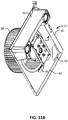
- FIGS. 11A to 11B are perspective views of a fan assembly coupled to an accessory assembly according to an example of the present disclosure.
- FIG. 12A is a front partial perspective view of an accessory assembly coupled to a fan assembly according to an example of the present disclosure.
- FIG. 12B is a top perspective view of a ventilation assembly according to an example of the present disclosure.
- a ventilation assembly 20 can include a fan assembly 22 and a main housing 24 .
- the main housing 24 can be mounted within an aperture in a wall or ceiling to a joist or other structure in the wall or ceiling.
- the main housing 24 can define an interior space and can include at least an inlet opening 26 aligned with the aperture in the wall or ceiling and an outlet opening 28 .
- the fan assembly 22 can be positioned within the interior space defined by the main housing 24 .
- the fan assembly 22 can include a fan 30 operable to create an inlet airflow through the aperture and inlet opening 26 into the interior space and an outlet airflow through the outlet opening 28 out of the interior space.
- the ventilation assembly 20 can be positioned within the wall or ceiling such that operating the fan 30 draws air through the aperture and inlet opening 26 from a first space and expelling the air through the outlet opening 28 to another space.
- the outlet opening 28 can be aligned with a second aperture or operably connected to ductwork to conduct the expelled air to a desired space.
- the fan assembly 22 can be releasably mounted to the main housing 24 such that the fan assembly 22 can be removed from the main housing 24 through the inlet opening 26 without removing the main housing 24 from the wall, ceiling or other building structure. In certain situations, it can be desirable to replace a damaged fan assembly 22 or replace the existing fan assembly 22 with a fan assembly 22 having improved or different operating parameters to retrofit the ventilation assembly 20 .
- the fan assembly 22 can also be configured to releasably engage an accessory assembly 46 to provide added functionality to the ventilation assembly 20 including, but not limited to additional lighting, sound producing elements, air quality monitoring and other features.
- the accessory assembly 46 is releasably mounted to the fan assembly 22 such that the accessory assembly 46 can be disengaged from the fan assembly 22 while the fan assembly 22 is mounted within the main housing 24 .
- the accessory assembly 46 can also be removed from the main housing 24 with the fan assembly 22 when the fan assembly 22 is disengaged from the main housing 24 and removed through the inlet opening 26 with the fan assembly 22 .
- the accessory assembly 46 can be mounted as a new accessory component 50 or replace an existing accessory component 50 .
- the fan assembly 22 can be installed within the main housing 24 with the accessory assembly 46 pre-mounted (i.e., at a factory during assembly of the ventilation assembly 20 or at an installation site just prior to or after installation of the main housing 24 .
- the modular configuration of the ventilation assembly 20 permits installation or replacement of the fan assembly 22 or accessory assembly 46 through the aperture and inlet opening 26 and without removal and reinstallation of the main housing 24 , which can cause damage to the wall or ceiling and associated support structure.
- the replacement fan assembly 22 and/or accessory can be an upgrade (i.e., as a retrofit) to the ventilation assembly 20 that would normally not include an accessory. Similarly, the fan assembly 22 or accessories can be removed and replaced without disconnecting the main housing 24 from attached ductwork.
- the main housing 24 includes the housing wall 32 defining the interior space within the main housing 24 .
- the housing wall 32 can further define the inlet opening 26 and the outlet opening 28 .
- the main housing 24 can be configured to house and mount structure for at least a portion of the various components and devices of the ventilation assembly 20 .
- the main housing 24 can comprise a plurality of shapes corresponding to the size and shape of the components and devices to be housed and the available space within the wall or ceiling.
- the main housing 24 can have shapes including, but not limited to, a rectangular box-like shape, an oval shape, a hemispherical shape, a spherical shape, a pyramidal shape, or any other shape.
- the main housing 24 can include materials suitable for supporting the weight of the fan assembly 22 and accessories and receiving fasteners for securing the main housing 24 to a wall or ceiling joint or other structure.
- the main housing 24 can comprise, but is not limited to, an aluminum-based metal, a steal or iron-based metal, a zinc-based metal, or a nickel and tin-based metal, injected molded polymers, thermo-formed polymers, thermosetting polymers, wood, particle-board, wood laminate, composite materials or combination of materials.
- the fan assembly 22 can include a fan 30 , a fan mount 45 and a motor mount plate 42 .
- the motor mount plate 42 can include a fan opening 44 .
- the fan mount 45 can receive at least one fastener to mount the fan 30 to the motor mount plate 42 such that position the fan 30 within the fan opening 44 .
- the fan 30 can comprise a centrifugal fan having a motor for rotating a blower wheel to draw air through the fan opening 44 .
- the fan mount 45 can be substantially linear as depicted in FIG. 2 .
- the fan mount 45 can be substantially arched as depicted in FIGS. 3A-3B .
- the blower wheel can be mechanically coupled to the motor using a main drive bolt.
- the fan 30 can comprise other conventional fans for drawing air and other gases through the fan opening 44 .
- the motor mount plate 42 can include an electrical port 48 through which wires can be threaded past the motor mount plate 42 .
- an accessory assembly 46 can include an accessory component 50 and an accessory mount 52 .
- the accessory component 50 can include an acoustic device 47 having an acoustic device housing 49 and at least one sound emitting device.
- the sound emitting device can include at least one loudspeaker (i.e., the housing and each sound emitting device is formed or coupled as a single unit and functional integral as a monolithic structure to emit sound).
- the acoustic device can be formed into any shape, but generally is shaped to provide a desirable acoustic response without blocking fan opening 44 .
- each loudspeaker can include a flexible, but semi-rigid membrane, or diaphragm 34 , 35 , attached to an electromagnetic coil.
- a current passed through the coil can cause the semi-rigid membrane, or diaphragm 34 , 35 , to at least partially move in the magnetic gap, thereby vibrating the diaphragm 34 , 35 , and producing sound waves, or an acoustic flow.
- the fan assembly 22 can also include a positioning mount 54 corresponding to the accessory mount 52 to releasably secure the accessory component 50 to the fan assembly 22 .
- the accessory mount 52 can include at least one hook element 56 and a tab portion 59 .
- the positioning mount 54 can include a receptacle 58 corresponding to each hook element 56 .
- the hook element 56 can be inserted into the receptacle 58 to position the accessory component 50 on the motor mount plate 42 as illustrated in FIG. 6A .
- the receptacle 58 can be angled away from the body of the motor mount plate 42 to complement the sloping angle of the motor mount plate 42 as illustrated in FIG. 7A .
- the hook element 56 is oriented such that the tab portion 59 is generally parallel to the motor mount plate 42 .
- a fastener can then be subsequently inserted through the tab portion 59 to fix the accessory component 50 to the fan assembly 22 as illustrated in FIG. 12A .
- the accessory mount 52 can be mounted to the positioning mount 54 prior to attachment of the accessory component 50 as illustrated in FIGS. 6A-6B .
- the accessory component 50 can be mounted to the accessory mount 52 prior to attachment of the accessory mount 52 to the positioning mount 54 as illustrated in FIGS.
- the accessory component 50 is angled to insert the hook element 56 into the receptacle 58 and rotated to secure the accessory component 50 to the motor mount plate 42 as illustrated in FIG. 7C .
- the accessory component 50 can be positioned on the motor mount plate 42 such that the accessory component 50 is positioned away from moving components such as the fan 30 .
- the accessory component 50 can be shaped to form a compact and desirable acoustic flow towards the inlet opening 26 when mounted to the motor mount plate 42 .
- the accessory component 50 can be coupled to the motor mount plate 42 such that the accessory component 50 and the motor mount plate 42 are resonantly coupled.
- the sound emitting device can be formed from any material that is readily shaped, including, but not limited to polymers, polymer-composites, metals, paper composites or fiber-based composites.
- injection-molded or thermo-formed polymeric materials can be molded to form functional components into the housing of the sound emitting device.
- the sound emitting device can include a resin treated cloth, fabric or non-woven material.
- the sound emitting device can include polymeric foams or thermoplastic elastomers over-molded onto the body of the diaphragm. The diaphragm can be integrally formed into the surrounding sound emitting device.
- the ventilation assembly 20 can include an electrical box having a power receptacle 62 .
- the power receptacle 62 can be connected to an external power source such as the power supply for the building or structure.
- the power receptacle 62 can include at least one terminal to which the fan 30 or accessory component 50 can be connected to supply power to the fan 30 or accessory component 50 .
- the accessory component 50 can be mounted on the motor mount plate 42 opposite from the power receptacle 62 . The arrangement increases the electromagnetic and acoustic isolation between the accessory component 50 and the power receptacle 62 .
- the motor mount plate 42 can include an electrical port 48 for interfacing with the power receptacle 62 .
- each terminal can be oriented to be accessible through the electrical port 48 while the power receptacle 62 prevents air flow through the electrical port 48 .
- a permanent split capacitor can be mounted to a surface of a structure of the building adjacent to the ventilation assembly 20 and electrically coupled to the speaker fan assembly with a motor power harness.
- the accessory component 50 can include an electrical circuit that is electrically coupled to the sound emitting device.
- the electrical circuit includes at least one switch capable of switching power to or off the speaker assembly.
- the sound emitting device can be powered when a user powers the fan 30 (i.e., when the user switches power to the fan assembly 22 for ventilation, the accessory component 50 can also be powered).
- the accessory component 50 can include a power supply that is independent of the electrical box coupled to the main housing 24 .
- the accessory component 50 can include a wireless receiver.
- the accessory component 50 can include a wireless receiver or transceiver, including, but not limited to a Bluetooth® transceiver or a WiFi receiver or transceiver.
- the accessory component 50 can include a wireless receiver or transceiver capable of responding to a two-way radio RF signal, a UHF or VHF signal (such as a citizen's band radio signal or other radio signal emitted from a ‘walkie talkie’ type device), and a near-field wireless signal.
- Bluetooth® is a registered trademark of Bluetooth SIG, Inc.
- the accessory component 50 can include a wireless receiver capable of responding to a zero generation wireless signal, a first generation wireless signal, a second generation wireless signal, a third generation wireless signal, a fourth generation wireless signal, or a fifth generation wireless signal.
- the wireless receiver can be powered when a user powers the fan 30 (i.e., when the user switches power to the fan assembly 22 for ventilation, the sound emitting device and the wireless receiver can also be powered).
- an acoustic member (such as at least one diaphragm) of the sound emitting device can emit sound based at least on a wireless signal received by the accessory component 50 .
- sound (such as music or speech) can be encoded by a user's wireless device that emits a wireless signal that is capable of being received and decoded by the wireless receiver within the fan speaker assembly and at least partially reproduced by the sound emitting device of the accessory component 50 .
- a user may program a wireless device to transmit a wireless signal to the accessory component 50 .
- the accessory component 50 can be a wireless receiver that accepts any signal sent by a user from a wireless device.
- the accessory component 50 may be wirelessly controlled.
- the accessory component 50 may be encoded by a user's wireless device that emits a wireless signal that is capable of being received and decoded by the wireless receiver within the fan speaker assembly to at least partially control at least one function of the speaker assembly and/or the fan speaker assembly.
- the main housing 24 is configured to be positioned within an aperture in a wall, ceiling or other building structure in a partially, or fully recessed position.
- the inlet opening 26 can be sized to correspond to the size and shape of the aperture in the wall, ceiling or other building structure.
- the main housing 24 can include a grille 34 having a fastener 36 for securing the grille 34 to the housing wall 32 over the inlet opening 26 to conceal the inlet opening 26 and restrict access to the interior space.
- the fastener 36 can be configured to be released and disengage the grille 34 from the main housing 24 to permit access to the interior space through the inlet opening 26 .
- the housing wall 32 can be configured to receive at least one fastener to secure the main housing 24 to joists or other building support structure.
- the housing wall 32 can include a duct connector assembly 38 at the outlet opening 28 for operably connecting the outlet opening 28 to a ventilation duct of a building.
- the duct connector assembly 38 can be pre-installed in a building structure in with the existing ductwork and the attached to the housing wall 32 when the housing wall 32 is mounted within the wall or ceiling.
- the main housing 24 is firstly installed in an existing cavity or aperture of a structure and the duct connector assembly is subsequently installed by connecting a ventilation duct of the ductwork with the outlet opening 28 of the main housing 24 .
- the fan assembly 22 can be positioned within the interior space of the main housing 24 .
- the motor mount plate 42 can be engaged to the housing wall 32 .
- the motor mount plate 42 can further include a releasable mount 60 for releasably engaging the motor mount plate 42 to the housing wall 32 .
- the releasable mount 60 can be configured to receive a removable fastener that can be inserted to engage the fan assembly 22 to the main housing 24 or removed to release the fan assembly 22 from the main housing 24 .
- the releasable mount 60 can include a flexible tab that can be releasably engaged into a corresponding receptacle in the housing wall 32 .
- the tab can be used to initially position the fan assembly 22 within the main housing 24 until the fastener can be inserted through the releasable mount 60 as depicted in FIG. 10 .
- the fan assembly 22 can be removed from the main housing 24 by removing the fastener and replaced or swapped with another fan assembly 22 .
- the main housing 24 can be mounted within the ceiling, wall or other building structure with the fan assembly 22 pre-installed.
- the main housing 24 can be mounted within the ceiling, wall or other building structure and the fan assembly 22 can than subsequently be installed by inserting the fan assembly 22 through the aperture and the inlet opening 26 .
- the inlet opening 26 can be sized to correspond to the dimensions of the housing wall 32 to receive the fan assembly 22 through the inlet opening 26 .
- the accessory component 50 can be mounted to the motor mount plate 42 by initially engaging the accessory mount 52 to the positioning mount 54 and subsequently inserting a fastener through the tabbed portion 58 .
- the accessory component 50 can be mounted to the fan assembly 22 prior to installation of the fan assembly within the main housing 24 .
- the fan assembly 22 can be pre-installed within the main housing 24 or installed after the main housing 24 is mounted within the aperture of the ceiling or wall.
- the accessory component 50 can be inserted through the aperture and inlet opening 26 . The accessory component 50 can then be engaged to the motor mount plate 42 in situ via the component mount 52 and positioning mount 54 .
- the engagement of the hook element 56 to the receptacle 58 retains the accessory component 50 in place on the motor mount plate 42 until the fastener is inserted through the tab portion 59 to fix the accessory component 50 .
- a mounted accessory component 50 can be replaced or swapped with a different accessory component.
- the fastener can be removed from the tab portion 59 and the accessory component 50 pivoted to disengage the hook element 56 from the receptacle 58 such that the accessory component 50 can be un-mounted from the fan assembly 22 .
- the motor mount plate 42 can be positioned to operate as a partition separating the inlet opening 26 and outlet opening 28 , wherein the fan opening 44 defines a fluid path between the inlet opening 26 and the outlet opening 28 .
- the fan 30 is operable to draw a fluid, such as air and other gases, through the inlet opening 26 and the fan opening 44 and expelling the fluid out the outlet opening 28 .
- the fluid can comprise, but is not limited to, air, other gases, vapor or combinations thereof.
- the fluid can comprise a smoke, ash, or other particulate in addition to air or other gases.
- the main housing 24 can include at least one damper flap positioned at the outlet opening 28 . The damper flap can control the backflow of a fluid into the interior space through the outlet opening 28 .
- the main housing 24 can include a scroll element for directing air from the blower wheel into the outlet opening 28 .
- the scroll element can comprise a readily shaped material including, but not limited to polymers, polymer-composites, metals, ceramics, wood, paper-based composite or laminate. Functional components can be molded or shaped into the scroll element to improve direction of fluids into the outlet opening 28 .
- the housing wall 32 can be shaped to operate as a scroll element for directing the fluid through the outlet opening 28 .
- the ventilation assembly 20 can be used to ventilate any room, area or space.
- the ventilation assembly 20 can be secured within an intermediate space, outside of the room, area or space, and coupled with one or more ventilation duct assemblies to provide ventilation to the room, area or space.
- a method for installing a ventilation assembly 20 can include providing a main housing 24 having a housing wall 32 defining an interior space and an inlet opening 26 for accessing the interior space.
- the method can also include providing a fan assembly 22 including a fan 30 mounted to a motor mount plate 42 , the motor mount plate 42 can include a releasable mount 60 .
- the method can include positioning the main housing 24 within an aperture in a building structure, wherein main housing 24 is oriented such that the inlet opening 26 faces the aperture.
- the method includes inserting the fan assembly 22 through the inlet opening 26 such that the motor mount plate 42 engages the housing wall 32 .
- the fan assembly 22 is inserted into the main housing 24 prior to positioning of the main housing 24 within the aperture in the building structure.
- the fan assembly 22 is inserted into the main housing 24 after the positioning of the main housing 24 within the aperture in the building structure, wherein the fan assembly 22 is inserted through the aperture and the inlet opening 26 into the interior space.
- the method can further include providing an accessory component 50 having an accessory mount 52 .
- the motor mount plate 42 can include a positioning mount 54 .
- the method can further include releasably engaging the accessory mount 52 to the positioning mount 54 to retain the accessory component 50 on the motor mount plate 54 .
- the method can further include inserting a fastener through a tab portion 59 of the accessory component 50 to fix the accessory component 50 to the motor mount plate 54 .
- the accessory component 50 can be mounted to the fan assembly 22 prior to mounting of the fan assembly 22 within the main housing 24 .
- the accessory component 50 can be mounted to the fan assembly 22 after to mounting of the fan assembly 22 within the main housing 24 , wherein the accessory component 50 is inserted through the inlet opening 26 to mount the accessory component 50 to the motor mount plate 54 .
- the accessory component 50 comprises an acoustic device 47 .
- the acoustic device 47 is depicted in FIGS. 1-4 and 11A-12B .
- the depicted embodiment of the acoustic device 47 includes an acoustic device housing 49 and first and second diaphragms 34 , 35 .
- the acoustic device housing 49 defines a first distal portion 90 , a second distal portion 94 and an intermediate portion 98 that extends between the distal portions 90 , 94 .
- One of the two diaphragms 34 , 35 is disposed within each of the first distal portion 90 and the second distal portion 94 as depicted.
- the first distal portion 90 and the second distal portion 94 are each substantially wider than the intermediate portion 98 , providing the acoustic device 47 with enlarged end portions and a generally U-shaped configuration.
- the first distal portion 90 includes a first surface 100 , a first outer surface 104 , a first connection surface 108 and a first lateral surface 112 .
- An obtuse angle is formed between the first surface 100 and the first connection surface 108 .
- the second distal portion 94 includes a second surface 120 , a second outer surface 124 , a second connection surface 128 and a second lateral surface 132 .
- An obtuse angle is formed between the second surface 120 and the second connection surface 128 .
- the first surface 100 is disposed substantially in parallel, and in a common plane, with the second surface 120 .
- the acoustic device 47 includes a rear surface 140 as depicted.
- the rear surface 140 extends from a first peripheral surface 144 to a second peripheral surface 148 .
- the rear surface 140 is disposed substantially parallel with the first surface 100 and the second surface 120 .
- An acute angle is formed between the rear surface 140 and the first outer surface 104
- another acute angle is formed between the rear surface 140 and the second outer surface 124 .
- an obtuse angle is formed between the first peripheral surface 144 and the first lateral surface 112
- another obtuse angle is formed between the first peripheral surface 144 and the rear surface 140
- An acute angle is formed between the first peripheral surface 144 and the first outer surface 104
- an obtuse angle is formed between the second peripheral surface 148 and the second lateral surface 132
- another obtuse angle is formed between the second peripheral surface 148 and the rear surface 140 .
- An acute angle is formed between the second peripheral surface 148 and the second outer surface 124 .
- the acoustic device 47 depicted in FIG. 3A also comprises the first outer surface 104 with a first ridge 105 that defines a first recessed portion 106 of the first distal portion 90 .
- a first edge 107 disposed within the first recessed portion 106 , defines a first opening 107 a .
- diaphragm 34 comprises a first annular diaphragm portion 34 a disposed within, and adjacent, the first opening 107 a .
- the first annular diaphragm portion 34 a connects the diaphragm 34 to the first edge 107 , as depicted.
- FIG. 3A also comprises the first outer surface 104 with a first ridge 105 that defines a first recessed portion 106 of the first distal portion 90 .
- a first edge 107 disposed within the first recessed portion 106 , defines a first opening 107 a .
- diaphragm 34 comprises a first annular diaphragm portion 34 a disposed within
- Diaphragm 35 comprises a second annular diaphragm portion 35 a disposed within, and adjacent, the second opening 127 a .
- the second annular diaphragm portion 35 a connects the diaphragm 35 to the second edge 127 .
- the intermediate portion 98 of the device 47 defines an intermediate surface 150 and an intermediate outer surface 154 .
- An obtuse angle is formed between the intermediate surface 150 and the first connection surface 108 , indicated as ⁇ in FIG. 3A .
- Another obtuse angle is formed between the intermediate surface 150 and the second connection surface 128 , indicated as ⁇ in FIG. 3A .
- Another obtuse angle is formed between the intermediate surface 150 and the intermediate outer surface 154 .
- the intermediate surface 150 includes a curved surface 158 , which defines a substantially constant curvature, as shown in FIG. 3A .
- the substantially constant curvature of the curved surface 158 is less than a constant curvature defined by the fan opening 44 , as defined by respective radii of curvature of the curved surface 158 and the fan opening 44 .
- the intermediate outer surface 154 is substantially parallel to a portion of the first outer surface 104 , and the intermediate outer surface 154 is substantially parallel to a portion of the second outer surface 124 .
- one or more of the rear surface 140 , first lateral surface 112 and second lateral surface 132 are in contact with, and/or adjacent, the housing wall 32 .
- the housing wall 32 includes, in some embodiments, a first housing wall 32 a , a second housing wall 32 b , a third housing wall 32 c and a fourth housing wall 32 d , as shown in FIG. 3A .
- housing walls 32 a and 32 b define a first corner 57 a
- housing walls 32 b and 32 c define a second corner 57 b
- housing walls 32 c and 32 d define a third corner 57 c
- housing walls 32 d and 32 a define a fourth corner 57 d .
- Each of the diaphragms 34 , 35 can be disposed substantially in one of the corners 57 a , 57 b , 57 c , 57 d .
- diaphragm 34 is disposed in the third corner 57 c and diaphragm 35 is disposed in the second corner 57 b.
- first surface 100 , first outer surface 104 , first connection surface 108 , first lateral surface 112 , second surface 120 , second outer surface 124 , second connection surface 128 , second lateral surface 132 , rear surface 140 , first peripheral surface 144 , second peripheral surface 148 , intermediate surface 150 and intermediate outer surface 154 are substantially flat surfaces.
- the rear surface 140 , first peripheral surface 144 and second peripheral surface 148 are substantially flat surfaces. Referring to FIG. 12B , a distance D 1 is defined as the height of the first surface 100 and a distance D 2 is defined as the height of the housing wall 32 , each measured from the motor mount plate 42 .
- D 1 extends substantially perpendicularly from the motor mount plate 42 .
- D 2 extends substantially perpendicularly from the motor mount plate 42 to a distal housing edge 33 .
- the distal housing edge 33 is disposed on a substantially opposite side of the housing wall 32 than is the motor mount plate 42 .
- a peripheral flange 37 extends from distal housing edge 33 and, in some embodiments, the peripheral flange 37 is substantially perpendicular to the housing wall 32 .
- a distance D 3 is defined as a difference between D 2 and D 1 , and D 3 is a non-zero distance. In other words, the height of the first surface 100 , D 1 , is less than an overall height of the housing wall 32 , D 2 , as measured from the motor mount plate 42 .
- the device 47 including diaphragms 34 , 35 , are recessed inward from the flange 37 .
- the first lateral surface 112 , the second lateral surface 132 and the rear surface 140 are adjacent the housing wall 32 in some embodiments.
- the motor mount plate 42 includes a motor mount plate peripheral flange 39 disposed at a perimeter of the motor mount plate 42 .
- the motor mount plate peripheral flange 39 connects the motor mount plate 42 to the housing wall 32 .
- a distance D 4 is defined as the width of the intermediate portion 98 between the rear surface 140 and the intermediate surface 150 , as measured perpendicularly to the rear surface 140 and equidistant between the first lateral surface 112 and the second lateral surface 132 .
- D 5 is defined as the width of the first distal portion 90 between the rear surface 140 and the first surface 100 and D 6 is defined as the width of the second distal portion 94 between the rear surface 140 and the second surface 120 .
- Each of D 5 and D 6 is measured perpendicularly to the rear surface 140 .
- D 5 is substantially equal to D 6 , and D 5 and D 6 are each greater than D 4 .
- a distance D 7 is defined as the width of the intermediate portion 98 between the rear surface 140 and the intermediate surface 150 , as measured perpendicularly to the rear surface 140 and between the first distal portion 90 and the area where D 4 is measured.
- a distance D 8 is defined as the width of the intermediate portion 98 between the rear surface 140 and the intermediate surface 150 , as measured perpendicularly to the rear surface 140 and between the second distal portion 94 and the area where D 4 is measured. Each of D 7 and D 8 is greater than D 4 .
- the acoustic device 47 can be disposed substantially within the main housing 24 adjacent the fan opening 44 .
- the fan opening 44 defined in the motor mount plate 42 leaves a narrow space between the fan opening 44 and intermediate portions of each side wall 32 of the main housing 24 as compared to relatively larger spaces between the fan opening 44 and each corner defined by the side walls 32 of the main housing 24 .
- the generally U-shaped configuration of the acoustic device 47 (defined by relative widths of the distal portions 90 , 94 and the intermediate portion 98 ) facilitates the disposition of the acoustic device 47 in these spaces without overlapping the fan opening 44 , which would impede air intake by the fan 30 .
- each of the first distal portion 90 and the second distal portion 94 is disposed substantially between the fan opening 44 and a different outer corner of the motor mount plate 42 .
- each of the first distal portion 90 and the second distal portion 94 is disposed substantially between the fan opening 44 and a different outer corner of the main housing 24 .
- the intermediate portion 98 connects the first distal portion 90 to the second distal portion 94 and the relatively narrow width of the intermediate portion 98 prevents the intermediate portion 98 from overlapping any portion of the fan opening 44 .
- each of the diaphragms 34 , 35 may be disposed substantially between the fan opening 44 and a different outer corner of the motor mount plate 42 . As also depicted in FIG. 3A , each of the diaphragms 34 , 35 may be disposed substantially between the fan opening 44 and a different outer corner of the side wall 32 . Each of the diaphragms 34 , 35 may be disposed substantially between the fan opening 44 and a different outer corner defined by the motor mount plate 42 and the side wall 32 , as shown in FIG. 3A . Further, each of the diaphragms 34 , 35 may be disposed, as also shown in FIG.
- first distal portion 90 , second distal portion 94 , acoustic device 47 , diaphragm 34 and/or diaphragm 35 is disposed radially outwardly of the fan opening 44 .
- first distal portion 90 , second distal portion 94 , acoustic device 47 , diaphragm 34 and/or diaphragm 35 is disposed radially outwardly of a drive shaft 53 , as defined relative to the fan opening 44 .
- the acoustic device 47 produces an acoustic flow towards the inlet opening 26 .
- the acoustic device 47 , diaphragms 34 , 35 and/or the acoustic device housing 49 are disposed outside of an air flow path through the fan opening 44 .
- Such an arrangement enables the ventilation assembly 20 to draw a flow of intake air through the fan opening 44 that is not hindered or obstructed by any portion of the acoustic device 47 , diaphragms 34 , 35 or acoustic device housing 49 .
- the general form-factor of the acoustic device 47 including relatively wide first and second distal portions 90 , 94 , corresponding to D 5 and D 6 , and a relatively narrow intermediate portion 98 , corresponding to D 4 , enables large diaphragms 34 , 35 to be used in the acoustic device 47 despite the narrow space available between the fan opening and portions of the main housing 24 . This enables the generation of a more desirable range and magnitude of acoustic flow by the acoustic device 47 .
- the relatively narrow intermediate portion 98 corresponding to D 4 , enables the acoustic device 47 to avoid the intake air flow through the inlet opening 26 while still including relatively large diaphragms 34 , 35 for desirable acoustic flow properties directed toward the inlet opening 26 .
- the terms “a” or “an” are used, as is common in patent documents, to include one or more than one, independent of any other instances or usages of “at least one” or “one or more.”
- the term “or” is used to refer to a nonexclusive or, such that “A or B” includes “A but not B,” “B but not A,” and “A and B,” unless otherwise indicated.
Landscapes
- Engineering & Computer Science (AREA)
- Mechanical Engineering (AREA)
- General Engineering & Computer Science (AREA)
- Chemical & Material Sciences (AREA)
- Combustion & Propulsion (AREA)
- Physics & Mathematics (AREA)
- Acoustics & Sound (AREA)
- Signal Processing (AREA)
- Structures Of Non-Positive Displacement Pumps (AREA)
Abstract
Description
Claims (19)
Priority Applications (1)
| Application Number | Priority Date | Filing Date | Title |
|---|---|---|---|
| US15/648,622 US10760579B2 (en) | 2013-11-05 | 2017-07-13 | Speaker fan system and method |
Applications Claiming Priority (3)
| Application Number | Priority Date | Filing Date | Title |
|---|---|---|---|
| US201361900281P | 2013-11-05 | 2013-11-05 | |
| US14/533,430 US9797404B2 (en) | 2013-11-05 | 2014-11-05 | Speaker fan system and method |
| US15/648,622 US10760579B2 (en) | 2013-11-05 | 2017-07-13 | Speaker fan system and method |
Related Parent Applications (1)
| Application Number | Title | Priority Date | Filing Date |
|---|---|---|---|
| US14/533,430 Continuation US9797404B2 (en) | 2013-11-05 | 2014-11-05 | Speaker fan system and method |
Publications (2)
| Publication Number | Publication Date |
|---|---|
| US20180058458A1 US20180058458A1 (en) | 2018-03-01 |
| US10760579B2 true US10760579B2 (en) | 2020-09-01 |
Family
ID=53007187
Family Applications (3)
| Application Number | Title | Priority Date | Filing Date |
|---|---|---|---|
| US14/533,430 Active 2035-10-25 US9797404B2 (en) | 2013-11-05 | 2014-11-05 | Speaker fan system and method |
| US15/648,622 Active 2035-06-10 US10760579B2 (en) | 2013-11-05 | 2017-07-13 | Speaker fan system and method |
| US15/720,505 Active US10054127B2 (en) | 2013-11-05 | 2017-09-29 | Speaker fan system and method |
Family Applications Before (1)
| Application Number | Title | Priority Date | Filing Date |
|---|---|---|---|
| US14/533,430 Active 2035-10-25 US9797404B2 (en) | 2013-11-05 | 2014-11-05 | Speaker fan system and method |
Family Applications After (1)
| Application Number | Title | Priority Date | Filing Date |
|---|---|---|---|
| US15/720,505 Active US10054127B2 (en) | 2013-11-05 | 2017-09-29 | Speaker fan system and method |
Country Status (4)
| Country | Link |
|---|---|
| US (3) | US9797404B2 (en) |
| CN (1) | CN104675722B (en) |
| CA (1) | CA2869771C (en) |
| HK (1) | HK1207143A1 (en) |
Cited By (1)
| Publication number | Priority date | Publication date | Assignee | Title |
|---|---|---|---|---|
| US12018850B2 (en) | 2020-08-13 | 2024-06-25 | Kohler Co. | Modular smart bathroom fan |
Families Citing this family (60)
| Publication number | Priority date | Publication date | Assignee | Title |
|---|---|---|---|---|
| US20090170421A1 (en) | 2008-01-02 | 2009-07-02 | Adrian John R | Grille |
| US12173925B2 (en) | 2010-10-11 | 2024-12-24 | Broan-Nutone Llc | Ventilating system |
| USD743520S1 (en) | 2013-06-20 | 2015-11-17 | Broan-Nutone Llc | Range hood |
| DE102013015985B4 (en) * | 2013-09-25 | 2016-08-18 | Stego-Holding Gmbh | Fan means |
| CN104675722B (en) | 2013-11-05 | 2021-03-30 | 布罗恩-努托恩有限责任公司 | Loudspeaker fan system and method |
| US9351060B2 (en) | 2014-02-14 | 2016-05-24 | Sonic Blocks, Inc. | Modular quick-connect A/V system and methods thereof |
| USD736903S1 (en) | 2014-05-01 | 2015-08-18 | Broan-Nutone Llc | Down draft grill |
| USD778425S1 (en) | 2015-01-08 | 2017-02-07 | Broan-Nutone Llc | Ventilator grill |
| USD784512S1 (en) | 2015-01-08 | 2017-04-18 | Broan-Nutone Llc | Ventilator grill |
| USD778424S1 (en) * | 2015-01-08 | 2017-02-07 | Broan-Nutone Llc | Ventilator grill |
| USD779050S1 (en) * | 2015-01-08 | 2017-02-14 | Broan-Nutone Llc | Ventilator grill |
| USD784511S1 (en) | 2015-01-08 | 2017-04-18 | Broan-Nutone Llc | Ventilator grill |
| USD804627S1 (en) | 2015-05-19 | 2017-12-05 | Broan-Nutone Llc | Vent hood |
| USD826391S1 (en) | 2015-05-19 | 2018-08-21 | Broan-Nutone Llc | Vent hood |
| USD814009S1 (en) | 2015-05-19 | 2018-03-27 | Broan-Nutone, Llc | Vent hood |
| CA165306S (en) | 2015-05-19 | 2017-01-23 | Broan Nu Tone Llc | Vent hood |
| USD785777S1 (en) | 2015-08-31 | 2017-05-02 | Broan-Nutone Llc | Vent hood |
| USD800294S1 (en) | 2015-09-14 | 2017-10-17 | Broan-Nutone Llc | Ventilation grill |
| USD799678S1 (en) | 2015-09-14 | 2017-10-10 | Broan-Nutone Llc | Ventilation grill |
| USD800295S1 (en) * | 2015-09-14 | 2017-10-17 | Broan-Nutone Llc | Ventilation grill |
| USD815724S1 (en) * | 2015-09-14 | 2018-04-17 | Broan-Nutone Llc | Ventilation grill |
| USD822821S1 (en) | 2015-09-14 | 2018-07-10 | Broan-Nutone, Llc | Ventilation grill |
| USD799677S1 (en) | 2015-09-14 | 2017-10-10 | Broan-Nutone Llc | Ventilation grill |
| USD799679S1 (en) * | 2015-09-14 | 2017-10-10 | Broan-Nutone Llc | Ventilation grill |
| USD816206S1 (en) | 2015-09-14 | 2018-04-24 | Broan-Nutone Llc | Ventilation grill |
| USD800892S1 (en) * | 2015-09-14 | 2017-10-24 | Broan-Nutone Llc | Ventilation grill |
| USD774018S1 (en) | 2015-10-06 | 2016-12-13 | Broan-Nutone Llc | Wireless speaker |
| USD808001S1 (en) * | 2016-03-14 | 2018-01-16 | Homewerks Worldwide, LLC | Square fan grille |
| USD799686S1 (en) * | 2016-03-21 | 2017-10-10 | Delta Electronics, Inc. | Grille |
| TWI591262B (en) * | 2016-04-18 | 2017-07-11 | 建準電機工業股份有限公司 | Ventilator |
| CN106016566B (en) * | 2016-07-11 | 2021-12-28 | 福建亚伦电子电器科技有限公司 | Wall-mounted air inlet machine |
| TWI607153B (en) * | 2016-07-15 | 2017-12-01 | 台達電子工業股份有限公司 | Smart ventilation fan system and smart ventilation fan device |
| USD897521S1 (en) | 2016-10-14 | 2020-09-29 | Broan-Nutone Llc | Vent hood |
| USD842449S1 (en) * | 2016-11-11 | 2019-03-05 | Broan-Nutone Llc | Grille |
| US10502215B2 (en) * | 2017-05-03 | 2019-12-10 | Regal Beloit America, Inc. | Blower assembly kit, device kit and associated method |
| GB2568235B (en) * | 2017-10-30 | 2023-02-01 | Zehnder Group Uk Ltd | Fixing plates |
| KR102116572B1 (en) | 2018-01-19 | 2020-05-28 | 엘지전자 주식회사 | Apparatus for both humidification and air cleaning |
| DE202019100292U1 (en) * | 2018-01-19 | 2019-05-09 | Lg Electronics Inc. | air cleaner |
| DE202019100290U1 (en) | 2018-01-19 | 2019-06-24 | Lg Electronics Inc. | air cleaner |
| US20190320251A1 (en) * | 2018-04-11 | 2019-10-17 | Hind Mohammed | Music playing fan assembly |
| US10989207B2 (en) * | 2018-05-18 | 2021-04-27 | Joseph Kraft | Low profile directional centrifugal ceiling fan |
| USD895783S1 (en) | 2018-05-22 | 2020-09-08 | Broan-Nutone Llc | Grille assembly for a bathroom ventilation fan |
| US10690137B2 (en) * | 2018-06-06 | 2020-06-23 | Delta Electronics, Inc. | Ventilation fan |
| USD902372S1 (en) | 2018-11-28 | 2020-11-17 | Broan-Nutone Llc | Ventilation grille |
| USD946136S1 (en) | 2018-11-28 | 2022-03-15 | Broan-Nutone Llc | Ventilation grille |
| USD909560S1 (en) | 2018-11-28 | 2021-02-02 | Broan-Nutone Llc | Ventilation grille |
| USD943730S1 (en) | 2018-11-28 | 2022-02-15 | Broan-Nutone Llc | Ventilation grille |
| USD908861S1 (en) | 2018-11-28 | 2021-01-26 | Broan-Nutone Llc | Ventilation grille |
| USD899582S1 (en) | 2019-01-22 | 2020-10-20 | Broan-Nutone Llc | Ventilation grille |
| USD898896S1 (en) | 2019-01-22 | 2020-10-13 | Broan-Nutone Llc | Ventilation grille |
| US11300305B2 (en) | 2019-02-15 | 2022-04-12 | Broan-Nutone Llc | Grille attachment feature for a ventilation system |
| US11326792B2 (en) | 2019-02-15 | 2022-05-10 | Broan-Nutone Llc | Grille attachment system for a ventilation system |
| USD946137S1 (en) | 2019-05-01 | 2022-03-15 | Broan-Nutone Llc | Ventilation grille |
| USD933194S1 (en) | 2019-06-24 | 2021-10-12 | Homewerks Worldwide, LLC | Fan grille |
| USD932611S1 (en) | 2019-06-24 | 2021-10-05 | Homewerks Worldwide, LLC | Fan grille |
| USD948025S1 (en) | 2019-11-26 | 2022-04-05 | Homewerks Worldwide, LLC | Fan grille |
| USD933195S1 (en) | 2019-11-26 | 2021-10-12 | Homewerks Worldwide, LLC | Fan grille |
| USD933809S1 (en) | 2019-11-26 | 2021-10-19 | Homewerks Worldwide, LLC | Fan grille |
| USD932612S1 (en) | 2019-11-26 | 2021-10-05 | Homewerks Worldwide, LLC | Fan grille |
| US11619241B2 (en) | 2021-07-09 | 2023-04-04 | Home Depot Product Authority, Llc | Ventilation fan installation system |
Citations (77)
| Publication number | Priority date | Publication date | Assignee | Title |
|---|---|---|---|---|
| US1722824A (en) | 1926-08-27 | 1929-07-30 | John H Roethel | Automobile ventilating device |
| US2588086A (en) | 1949-03-12 | 1952-03-04 | Maurice S Cole | Speaker and heater unit for drive-in theaters |
| US2612830A (en) | 1949-03-24 | 1952-10-07 | James R Kendrick | Air conditioning and speaker unit for automobiles |
| US2613757A (en) | 1949-02-07 | 1952-10-14 | Herman M Melzer | Portable loud-speaker heater attachment for drive-in theaters |
| US2683407A (en) | 1952-01-12 | 1954-07-13 | Takach Sigmund | Speaker-heater apparatus for drive-in theaters |
| US3165587A (en) | 1962-10-08 | 1965-01-12 | Richard L Alderson | Multiple-loudspeaker system |
| US3927316A (en) | 1974-06-07 | 1975-12-16 | Zenith Radio Corp | Wireless speaker system using infra-red link |
| US4371814A (en) | 1981-09-09 | 1983-02-01 | Silent Running Corporation | Infrared transmitter and control circuit |
| US4528620A (en) | 1984-01-23 | 1985-07-09 | Modulite Corporation | Audio light chandelier |
| JPS6165092A (en) | 1984-09-04 | 1986-04-03 | Suiden:Kk | Ceiling fan with audio device |
| US5343713A (en) | 1992-02-19 | 1994-09-06 | Hitachi, Ltd. | Active noise control apparatus for three-dimensional space |
| JPH06305325A (en) | 1993-04-27 | 1994-11-01 | Matsushita Electric Ind Co Ltd | Air purifier for automobile |
| US5410735A (en) | 1992-01-17 | 1995-04-25 | Borchardt; Robert L. | Wireless signal transmission systems, methods and apparatus |
| US5448495A (en) * | 1994-03-24 | 1995-09-05 | Enlight Corporation | Multifunctional frame assembly with fan and speaker for a personal computer |
| US5664872A (en) | 1993-11-23 | 1997-09-09 | Smiths Industries Plc | Combined lamp and fan assembly |
| US5884694A (en) | 1997-03-26 | 1999-03-23 | Tanenbaum; Aaron | Bathroom dehumidifier method and apparatus |
| US5980057A (en) | 1997-11-10 | 1999-11-09 | Recoton Corporation | Speaker light unit connected to conventional electrical light socket |
| US6215885B1 (en) | 1997-06-26 | 2001-04-10 | George R. Geiger | Audio speaker |
| USD444869S1 (en) | 2000-01-05 | 2001-07-10 | Chung Lun Yip | Exhaust fan |
| USD457616S1 (en) | 2001-02-07 | 2002-05-21 | Matsushita Electric Industrial Co., Ltd. | Ceiling recessed type ventilating fan |
| US6466832B1 (en) | 1998-08-24 | 2002-10-15 | Altec Lansing R & D Center Israel | High quality wireless audio speakers |
| US6558003B2 (en) * | 2000-12-28 | 2003-05-06 | Kabushiki Kaisha Toshiba | Attachable/detachable silencer and projection type projector apparatus with the same |
| US6577081B2 (en) | 1999-10-08 | 2003-06-10 | Elumina Lighting Technologies, Inc. | Safety shield assembly for electrical apparatus |
| US6580228B1 (en) | 2000-08-22 | 2003-06-17 | Light Sciences Corporation | Flexible substrate mounted solid-state light sources for use in line current lamp sockets |
| US6578808B1 (en) * | 2002-06-13 | 2003-06-17 | Sound Advance Systems, Inc. | Mounting assembly for mounting a device in a barrier |
| KR20040013864A (en) | 2002-08-08 | 2004-02-14 | (주)모바일핸즈 | Game terminal apparatus and manageable Method for the same and A Computer- readable Storage Meduim storing the method |
| US6731761B1 (en) | 2000-03-10 | 2004-05-04 | Ford Global Technologies, Llc | Wireless remote speakers for an automotive vehicle |
| US20050078837A1 (en) * | 2003-10-11 | 2005-04-14 | Charles Hornback | Wireless speaker system for use with ceiling fans |
| JP2005127688A (en) | 2003-08-18 | 2005-05-19 | Max Co Ltd | Air conditioner, and speaker system, bathroom, and house structure provided therewith |
| JP2005171838A (en) | 2003-12-10 | 2005-06-30 | Matsushita Electric Ind Co Ltd | Ventilation fan |
| US20060073008A1 (en) * | 2003-11-21 | 2006-04-06 | Broan-Nutone Llc | Modular ventilating exhaust fan assembly and method |
| US7076204B2 (en) | 2001-10-30 | 2006-07-11 | Unwired Technology Llc | Multiple channel wireless communication system |
| JP2007010078A (en) | 2005-07-01 | 2007-01-18 | Ckd Corp | Actuator with rod |
| WO2007083877A1 (en) | 2006-01-18 | 2007-07-26 | Lg Electronics, Inc. | Indoor unit of air conditioner |
| JP2007240124A (en) | 2006-03-13 | 2007-09-20 | Matsushita Electric Ind Co Ltd | Ventilator |
| US20080064318A1 (en) | 2006-09-07 | 2008-03-13 | Brushstrokes Design Studio, Inc. | Ventilation fan and hanging light fixture arrangement |
| JP2008164206A (en) | 2006-12-27 | 2008-07-17 | Max Co Ltd | Air conditioning device |
| JP2008190765A (en) | 2007-02-02 | 2008-08-21 | Max Co Ltd | Bathroom air conditioner |
| JP2008190764A (en) | 2007-02-02 | 2008-08-21 | Max Co Ltd | Bathroom air conditioner |
| USD580542S1 (en) | 2008-02-04 | 2008-11-11 | Panasonic Corporation | Ceiling ventilating fan |
| USD581508S1 (en) | 2007-10-26 | 2008-11-25 | Matsushita Electric Industrial Co., Ltd. | Ceiling recessed type ventilating fan |
| US20080298045A1 (en) | 2005-06-17 | 2008-12-04 | Doug Wright | Recessed light fixture and speaker combination |
| US20090067663A1 (en) | 2006-03-17 | 2009-03-12 | Mitek Corp., Inc. | Omni-directional speaker lamp |
| US7535341B2 (en) | 2006-03-23 | 2009-05-19 | Haase Edward H | Combination speaker / light fixture |
| USD593193S1 (en) | 2005-10-12 | 2009-05-26 | Jackson James S | Crawlspace door fan |
| KR20090063326A (en) | 2007-12-14 | 2009-06-18 | 주식회사 중외엔비텍 | Emotional stimulation device using ceiling mounted air purifier |
| JP2009228954A (en) | 2008-03-21 | 2009-10-08 | Toto Ltd | Bathroom ventilation heating apparatus |
| US20100028134A1 (en) * | 2007-01-22 | 2010-02-04 | Alon Slapak | Quiet fan incorporating active noise control (anc) |
| JP2010071475A (en) | 2008-09-16 | 2010-04-02 | Panasonic Corp | Ceiling embedded ventilation fan |
| CN201502556U (en) | 2009-08-20 | 2010-06-09 | 廖元聪 | Bathroom air exhauster |
| JP2010190506A (en) | 2009-02-19 | 2010-09-02 | Panasonic Corp | Ventilator |
| CN101881503A (en) | 2010-07-15 | 2010-11-10 | Tcl空调器(中山)有限公司 | Wall-mounted air conditioner indoor unit |
| US7844060B2 (en) | 2005-07-12 | 2010-11-30 | Terry Zulkowski | Remote control single crystal speaker system |
| GB2471069A (en) | 2009-06-11 | 2010-12-22 | Ming Jen Hsiao | An aromatic atomiser having a light transmissive cover and light display with music |
| US7862371B1 (en) | 2008-01-09 | 2011-01-04 | Terry David Johnson | Light socket adapter for a fan holding device |
| USD632775S1 (en) | 2009-03-10 | 2011-02-15 | Microsoft Corporation | Cooling unit |
| JP2011094893A (en) | 2009-10-30 | 2011-05-12 | Panasonic Corp | Ventilating device |
| US8042961B2 (en) | 2007-12-02 | 2011-10-25 | Andrew Massara | Audio lamp |
| US8073182B2 (en) * | 2008-08-15 | 2011-12-06 | Hong Fu Jin Precision Industry (Shenzhen) Co., Ltd. | Mounting apparatus for speaker |
| CN202092255U (en) | 2011-05-20 | 2011-12-28 | 周辰洋 | Bathroom air conditioner |
| CN102588827A (en) | 2010-10-11 | 2012-07-18 | 布罗恩-努托恩有限责任公司 | Lighting and ventilating system and method |
| US8249731B2 (en) | 2007-05-24 | 2012-08-21 | Alexander Bach Tran | Smart air ventilation system |
| US20120274767A1 (en) | 2003-10-11 | 2012-11-01 | Cb Llc | Ceiling fan accessory unit |
| US20120313553A1 (en) | 2011-06-13 | 2012-12-13 | Teng-Chen Ko | Ceiling fan with illumination mechanism |
| CN202613644U (en) | 2012-06-13 | 2012-12-19 | 陆天波 | Music air-conditioner fan |
| US20130062437A1 (en) | 2011-09-06 | 2013-03-14 | Kenneth Scott Hanna | Shower and speaker assembly |
| US20130084793A1 (en) | 2011-09-29 | 2013-04-04 | Panasonic Corporation | Ceiling mounted ventilation fan |
| US8620016B2 (en) | 2006-08-21 | 2013-12-31 | Ksc Industries Incorporated | Magnetic speaker grill |
| US8625833B1 (en) | 2012-12-11 | 2014-01-07 | Kenneth Armwood | Portable pressurization headphones |
| US8763750B1 (en) * | 2012-12-22 | 2014-07-01 | Homewerks Worldwide, LLC | Audio equipped fan |
| US8770949B2 (en) | 2008-09-04 | 2014-07-08 | Delta T Corporation | Ceiling fan |
| US20150125292A1 (en) | 2013-11-05 | 2015-05-07 | Daniel L. Karst | Speaker fan system and method |
| US20160029109A1 (en) * | 2014-07-28 | 2016-01-28 | Delta Electronics, Inc. | Ventilation fan with speaker |
| USD754835S1 (en) | 2014-09-05 | 2016-04-26 | Panasonic Intellectual Property Management Co., Ltd. | Centrifugal fan |
| US9398357B2 (en) * | 2012-12-22 | 2016-07-19 | Homewerks Worldwide, LLC | Audio equipped fan |
| US9414142B1 (en) * | 2013-09-06 | 2016-08-09 | Chien Luen Industries Co., Ltd., Inc. | Wireless bath fan speaker |
| US9508337B2 (en) * | 2013-05-17 | 2016-11-29 | Ask Industries Societa Per Azioni | Low-noise fume extractor hood |
Family Cites Families (8)
| Publication number | Priority date | Publication date | Assignee | Title |
|---|---|---|---|---|
| US6585486B2 (en) * | 2001-07-12 | 2003-07-01 | Honeywell International Inc. | Electrical appliance enclosure with removable side wall |
| CN1654881A (en) * | 2004-01-15 | 2005-08-17 | 潘志标 | Exhaust Lighting Fixtures |
| CN201071841Y (en) * | 2007-06-12 | 2008-06-11 | 杭州奥普卫厨科技有限公司 | Hidden ventilation fan |
| US7884060B1 (en) | 2009-08-12 | 2011-02-08 | Conopco, Inc. | Concentrated liquid soap formulations having readily pumpable viscosity |
| CN201747642U (en) * | 2010-08-11 | 2011-02-16 | 何世健 | Pipeline type exhaust fan with lamp |
| US10907843B2 (en) * | 2011-11-18 | 2021-02-02 | Broan-Nutone Llc | Ventilating system and method |
| US9344787B2 (en) * | 2012-12-22 | 2016-05-17 | Homewerks Worldwide, LLC | Audio equipped fan |
| CN103334960B (en) * | 2013-07-04 | 2016-04-20 | 佛山市南海九洲普惠风机有限公司 | A kind of top suction type ventilation fan |
-
2014
- 2014-11-05 CN CN201410637353.2A patent/CN104675722B/en not_active Expired - Fee Related
- 2014-11-05 CA CA2869771A patent/CA2869771C/en active Active
- 2014-11-05 US US14/533,430 patent/US9797404B2/en active Active
-
2015
- 2015-08-11 HK HK15107766.0A patent/HK1207143A1/en unknown
-
2017
- 2017-07-13 US US15/648,622 patent/US10760579B2/en active Active
- 2017-09-29 US US15/720,505 patent/US10054127B2/en active Active
Patent Citations (80)
| Publication number | Priority date | Publication date | Assignee | Title |
|---|---|---|---|---|
| US1722824A (en) | 1926-08-27 | 1929-07-30 | John H Roethel | Automobile ventilating device |
| US2613757A (en) | 1949-02-07 | 1952-10-14 | Herman M Melzer | Portable loud-speaker heater attachment for drive-in theaters |
| US2588086A (en) | 1949-03-12 | 1952-03-04 | Maurice S Cole | Speaker and heater unit for drive-in theaters |
| US2612830A (en) | 1949-03-24 | 1952-10-07 | James R Kendrick | Air conditioning and speaker unit for automobiles |
| US2683407A (en) | 1952-01-12 | 1954-07-13 | Takach Sigmund | Speaker-heater apparatus for drive-in theaters |
| US3165587A (en) | 1962-10-08 | 1965-01-12 | Richard L Alderson | Multiple-loudspeaker system |
| US3927316A (en) | 1974-06-07 | 1975-12-16 | Zenith Radio Corp | Wireless speaker system using infra-red link |
| US4371814A (en) | 1981-09-09 | 1983-02-01 | Silent Running Corporation | Infrared transmitter and control circuit |
| US4528620A (en) | 1984-01-23 | 1985-07-09 | Modulite Corporation | Audio light chandelier |
| JPS6165092A (en) | 1984-09-04 | 1986-04-03 | Suiden:Kk | Ceiling fan with audio device |
| US5410735A (en) | 1992-01-17 | 1995-04-25 | Borchardt; Robert L. | Wireless signal transmission systems, methods and apparatus |
| US5343713A (en) | 1992-02-19 | 1994-09-06 | Hitachi, Ltd. | Active noise control apparatus for three-dimensional space |
| JPH06305325A (en) | 1993-04-27 | 1994-11-01 | Matsushita Electric Ind Co Ltd | Air purifier for automobile |
| US5664872A (en) | 1993-11-23 | 1997-09-09 | Smiths Industries Plc | Combined lamp and fan assembly |
| US5448495A (en) * | 1994-03-24 | 1995-09-05 | Enlight Corporation | Multifunctional frame assembly with fan and speaker for a personal computer |
| US5884694A (en) | 1997-03-26 | 1999-03-23 | Tanenbaum; Aaron | Bathroom dehumidifier method and apparatus |
| US6215885B1 (en) | 1997-06-26 | 2001-04-10 | George R. Geiger | Audio speaker |
| US5980057A (en) | 1997-11-10 | 1999-11-09 | Recoton Corporation | Speaker light unit connected to conventional electrical light socket |
| US6466832B1 (en) | 1998-08-24 | 2002-10-15 | Altec Lansing R & D Center Israel | High quality wireless audio speakers |
| US6577081B2 (en) | 1999-10-08 | 2003-06-10 | Elumina Lighting Technologies, Inc. | Safety shield assembly for electrical apparatus |
| USD444869S1 (en) | 2000-01-05 | 2001-07-10 | Chung Lun Yip | Exhaust fan |
| US6731761B1 (en) | 2000-03-10 | 2004-05-04 | Ford Global Technologies, Llc | Wireless remote speakers for an automotive vehicle |
| US6580228B1 (en) | 2000-08-22 | 2003-06-17 | Light Sciences Corporation | Flexible substrate mounted solid-state light sources for use in line current lamp sockets |
| US6558003B2 (en) * | 2000-12-28 | 2003-05-06 | Kabushiki Kaisha Toshiba | Attachable/detachable silencer and projection type projector apparatus with the same |
| USD457616S1 (en) | 2001-02-07 | 2002-05-21 | Matsushita Electric Industrial Co., Ltd. | Ceiling recessed type ventilating fan |
| US7076204B2 (en) | 2001-10-30 | 2006-07-11 | Unwired Technology Llc | Multiple channel wireless communication system |
| US6578808B1 (en) * | 2002-06-13 | 2003-06-17 | Sound Advance Systems, Inc. | Mounting assembly for mounting a device in a barrier |
| KR20040013864A (en) | 2002-08-08 | 2004-02-14 | (주)모바일핸즈 | Game terminal apparatus and manageable Method for the same and A Computer- readable Storage Meduim storing the method |
| JP2005127688A (en) | 2003-08-18 | 2005-05-19 | Max Co Ltd | Air conditioner, and speaker system, bathroom, and house structure provided therewith |
| US20050078837A1 (en) * | 2003-10-11 | 2005-04-14 | Charles Hornback | Wireless speaker system for use with ceiling fans |
| US20120274767A1 (en) | 2003-10-11 | 2012-11-01 | Cb Llc | Ceiling fan accessory unit |
| US7455500B2 (en) | 2003-11-21 | 2008-11-25 | Broan-Nu Tone Llc | Modular ventilating exhaust fan assembly and method |
| US20060073008A1 (en) * | 2003-11-21 | 2006-04-06 | Broan-Nutone Llc | Modular ventilating exhaust fan assembly and method |
| JP2005171838A (en) | 2003-12-10 | 2005-06-30 | Matsushita Electric Ind Co Ltd | Ventilation fan |
| US20080298045A1 (en) | 2005-06-17 | 2008-12-04 | Doug Wright | Recessed light fixture and speaker combination |
| JP2007010078A (en) | 2005-07-01 | 2007-01-18 | Ckd Corp | Actuator with rod |
| US7844060B2 (en) | 2005-07-12 | 2010-11-30 | Terry Zulkowski | Remote control single crystal speaker system |
| USD593193S1 (en) | 2005-10-12 | 2009-05-26 | Jackson James S | Crawlspace door fan |
| WO2007083877A1 (en) | 2006-01-18 | 2007-07-26 | Lg Electronics, Inc. | Indoor unit of air conditioner |
| JP2007240124A (en) | 2006-03-13 | 2007-09-20 | Matsushita Electric Ind Co Ltd | Ventilator |
| US20090067663A1 (en) | 2006-03-17 | 2009-03-12 | Mitek Corp., Inc. | Omni-directional speaker lamp |
| US7606379B2 (en) | 2006-03-17 | 2009-10-20 | Mitek Corp, Inc. | Omni-directional speaker lamp |
| US7535341B2 (en) | 2006-03-23 | 2009-05-19 | Haase Edward H | Combination speaker / light fixture |
| US8620016B2 (en) | 2006-08-21 | 2013-12-31 | Ksc Industries Incorporated | Magnetic speaker grill |
| US20080064318A1 (en) | 2006-09-07 | 2008-03-13 | Brushstrokes Design Studio, Inc. | Ventilation fan and hanging light fixture arrangement |
| JP2008164206A (en) | 2006-12-27 | 2008-07-17 | Max Co Ltd | Air conditioning device |
| US20100028134A1 (en) * | 2007-01-22 | 2010-02-04 | Alon Slapak | Quiet fan incorporating active noise control (anc) |
| JP2008190764A (en) | 2007-02-02 | 2008-08-21 | Max Co Ltd | Bathroom air conditioner |
| JP2008190765A (en) | 2007-02-02 | 2008-08-21 | Max Co Ltd | Bathroom air conditioner |
| US8249731B2 (en) | 2007-05-24 | 2012-08-21 | Alexander Bach Tran | Smart air ventilation system |
| USD581508S1 (en) | 2007-10-26 | 2008-11-25 | Matsushita Electric Industrial Co., Ltd. | Ceiling recessed type ventilating fan |
| US8042961B2 (en) | 2007-12-02 | 2011-10-25 | Andrew Massara | Audio lamp |
| KR20090063326A (en) | 2007-12-14 | 2009-06-18 | 주식회사 중외엔비텍 | Emotional stimulation device using ceiling mounted air purifier |
| US7862371B1 (en) | 2008-01-09 | 2011-01-04 | Terry David Johnson | Light socket adapter for a fan holding device |
| USD580542S1 (en) | 2008-02-04 | 2008-11-11 | Panasonic Corporation | Ceiling ventilating fan |
| JP2009228954A (en) | 2008-03-21 | 2009-10-08 | Toto Ltd | Bathroom ventilation heating apparatus |
| US8073182B2 (en) * | 2008-08-15 | 2011-12-06 | Hong Fu Jin Precision Industry (Shenzhen) Co., Ltd. | Mounting apparatus for speaker |
| US8770949B2 (en) | 2008-09-04 | 2014-07-08 | Delta T Corporation | Ceiling fan |
| JP2010071475A (en) | 2008-09-16 | 2010-04-02 | Panasonic Corp | Ceiling embedded ventilation fan |
| JP2010190506A (en) | 2009-02-19 | 2010-09-02 | Panasonic Corp | Ventilator |
| USD632775S1 (en) | 2009-03-10 | 2011-02-15 | Microsoft Corporation | Cooling unit |
| GB2471069A (en) | 2009-06-11 | 2010-12-22 | Ming Jen Hsiao | An aromatic atomiser having a light transmissive cover and light display with music |
| CN201502556U (en) | 2009-08-20 | 2010-06-09 | 廖元聪 | Bathroom air exhauster |
| JP2011094893A (en) | 2009-10-30 | 2011-05-12 | Panasonic Corp | Ventilating device |
| CN101881503A (en) | 2010-07-15 | 2010-11-10 | Tcl空调器(中山)有限公司 | Wall-mounted air conditioner indoor unit |
| US8967832B2 (en) * | 2010-10-11 | 2015-03-03 | Broan-Nutone Llc | Lighting and ventilating system and method |
| CN102588827A (en) | 2010-10-11 | 2012-07-18 | 布罗恩-努托恩有限责任公司 | Lighting and ventilating system and method |
| CN202092255U (en) | 2011-05-20 | 2011-12-28 | 周辰洋 | Bathroom air conditioner |
| US20120313553A1 (en) | 2011-06-13 | 2012-12-13 | Teng-Chen Ko | Ceiling fan with illumination mechanism |
| US20130062437A1 (en) | 2011-09-06 | 2013-03-14 | Kenneth Scott Hanna | Shower and speaker assembly |
| US20130084793A1 (en) | 2011-09-29 | 2013-04-04 | Panasonic Corporation | Ceiling mounted ventilation fan |
| CN202613644U (en) | 2012-06-13 | 2012-12-19 | 陆天波 | Music air-conditioner fan |
| US8625833B1 (en) | 2012-12-11 | 2014-01-07 | Kenneth Armwood | Portable pressurization headphones |
| US8763750B1 (en) * | 2012-12-22 | 2014-07-01 | Homewerks Worldwide, LLC | Audio equipped fan |
| US9398357B2 (en) * | 2012-12-22 | 2016-07-19 | Homewerks Worldwide, LLC | Audio equipped fan |
| US9508337B2 (en) * | 2013-05-17 | 2016-11-29 | Ask Industries Societa Per Azioni | Low-noise fume extractor hood |
| US9414142B1 (en) * | 2013-09-06 | 2016-08-09 | Chien Luen Industries Co., Ltd., Inc. | Wireless bath fan speaker |
| US20150125292A1 (en) | 2013-11-05 | 2015-05-07 | Daniel L. Karst | Speaker fan system and method |
| US20160029109A1 (en) * | 2014-07-28 | 2016-01-28 | Delta Electronics, Inc. | Ventilation fan with speaker |
| USD754835S1 (en) | 2014-09-05 | 2016-04-26 | Panasonic Intellectual Property Management Co., Ltd. | Centrifugal fan |
Non-Patent Citations (12)
| Title |
|---|
| "Lighting California's Future: Smart Light-Emitting Diode Lighting in Residential Fans", Mar. 2011. Pier Final Project Report, California Energy Commission, CEC-500-2011-018. |
| "New Baffistinis Harley-Davidson Speaker Grill Covers", Jul. 23, 2010. URL: http://cyrilhuzeblog.com/2010/07/23/new-battistinis-harley-davidson-speaker-grill-covers/. |
| "What is the difference between Bluetooth technology and Wi-Fl?", Oct. 22, 2011. URL: http://www.bluetooth.com/Pages/Wi-Fi.aspx. |
| English Translation of portions of Jul. 26, 2018 Office Action in Chinese Patent Application No. 201410637353.2. |
| First Office Action issued in corresponding Chinese Application No. 201410637353.2 dated Sep. 26, 2016 (26 pgs). |
| Fourth Office Action issued in corresponding Chinese Application No. 201410637353.2 dated Mar. 26, 2018 (20 pgs). |
| Office Action as issued in Corresponding Chinese Patent Application No. 201410637353.2; dated Jul. 26, 2018. |
| Response to the First Office Action in corresponding Chinese Application No. 201410637353.2 filed Dec. 23, 2016, 2016 (39 pgs). |
| Response to the Second Office Action in corresponding Chinese Application No. 201410637353.2 filed Dec. 28, 2017 (10 pgs). |
| Response to the Second Office Action in corresponding Chinese Application No. 201410637353.2 filed Jul. 17, 2017, 2016 (13 pgs). |
| Second Office Action issued in corresponding Chinese Application No. 201410637353.2 dated May 22, 2017 (17 pgs). |
| Third Office Action issued in corresponding Chinese Application No. 201410637353.2 dated Oct. 31, 2017 (13 pgs). |
Cited By (1)
| Publication number | Priority date | Publication date | Assignee | Title |
|---|---|---|---|---|
| US12018850B2 (en) | 2020-08-13 | 2024-06-25 | Kohler Co. | Modular smart bathroom fan |
Also Published As
| Publication number | Publication date |
|---|---|
| US9797404B2 (en) | 2017-10-24 |
| US20180023581A1 (en) | 2018-01-25 |
| CA2869771C (en) | 2022-09-13 |
| CN104675722A (en) | 2015-06-03 |
| US20180058458A1 (en) | 2018-03-01 |
| US20150125292A1 (en) | 2015-05-07 |
| US10054127B2 (en) | 2018-08-21 |
| HK1207143A1 (en) | 2016-01-22 |
| CN104675722B (en) | 2021-03-30 |
| CA2869771A1 (en) | 2016-05-05 |
Similar Documents
| Publication | Publication Date | Title |
|---|---|---|
| US10760579B2 (en) | Speaker fan system and method | |
| US10113550B2 (en) | Ventilation system and method | |
| CA2880875A1 (en) | Ventilation system and method | |
| US9945580B2 (en) | Ventilation system | |
| CA2762259C (en) | Ventilating system and method | |
| US20150226443A1 (en) | Ventilation system and method | |
| US9414142B1 (en) | Wireless bath fan speaker | |
| US11619241B2 (en) | Ventilation fan installation system | |
| US20130196588A1 (en) | Ceiling fan | |
| US11732914B2 (en) | Grille attachment feature for a ventilation system | |
| CA3163751C (en) | Speaker fan system and method | |
| CN216307983U (en) | Indoor unit of air conditioner | |
| WO2007114908A3 (en) | Condenser shroud assembly for a direct current air conditioning system | |
| JP3260651B2 (en) | Duct ventilation fan | |
| US11614257B2 (en) | Housing assembly for air handling apparatus and air handling apparatus | |
| CN222165132U (en) | Fresh air sound absorption module and air conditioner | |
| CN210891902U (en) | Air conditioner | |
| JP2013142499A (en) | Ventilation device | |
| CN110307627A (en) | Installing support, domestic appliance's installation component and humidifier |
Legal Events
| Date | Code | Title | Description |
|---|---|---|---|
| AS | Assignment |
Owner name: BROAN-NUTONE LLC, WISCONSIN Free format text: ASSIGNMENT OF ASSIGNORS INTEREST;ASSIGNORS:KARST, DANIEL L.;PUFFER, BENJAMIN THORPE;COFFEY, BRENT ELLIOT;SIGNING DATES FROM 20180105 TO 20180108;REEL/FRAME:045081/0056 |
|
| STPP | Information on status: patent application and granting procedure in general |
Free format text: DOCKETED NEW CASE - READY FOR EXAMINATION |
|
| STPP | Information on status: patent application and granting procedure in general |
Free format text: NON FINAL ACTION MAILED |
|
| STPP | Information on status: patent application and granting procedure in general |
Free format text: RESPONSE TO NON-FINAL OFFICE ACTION ENTERED AND FORWARDED TO EXAMINER |
|
| STPP | Information on status: patent application and granting procedure in general |
Free format text: FINAL REJECTION MAILED |
|
| STPP | Information on status: patent application and granting procedure in general |
Free format text: ADVISORY ACTION MAILED |
|
| STCV | Information on status: appeal procedure |
Free format text: NOTICE OF APPEAL FILED |
|
| STPP | Information on status: patent application and granting procedure in general |
Free format text: NOTICE OF ALLOWANCE MAILED -- APPLICATION RECEIVED IN OFFICE OF PUBLICATIONS |
|
| STPP | Information on status: patent application and granting procedure in general |
Free format text: PUBLICATIONS -- ISSUE FEE PAYMENT RECEIVED |
|
| STCF | Information on status: patent grant |
Free format text: PATENTED CASE |
|
| AS | Assignment |
Owner name: GOLDMAN SACHS BANK USA, AS COLLATERAL AGENT, NEW YORK Free format text: SECURITY INTEREST;ASSIGNORS:BROAN-NUTONE LLC;NORTEK AIR SOLUTIONS, LLC;NORTEK GLOBAL HVAC, LLC;AND OTHERS;REEL/FRAME:056647/0868 Effective date: 20210621 Owner name: U.S. BANK NATIONAL ASSOCIATION, AS COLLATERAL AGENT, TENNESSEE Free format text: SECURITY INTEREST;ASSIGNORS:BROAN-NUTONE LLC;NORTEK AIR SOLUTIONS, LLC;NORTEK GLOBAL HVAC, LLC;AND OTHERS;REEL/FRAME:056650/0303 Effective date: 20210621 |
|
| MAFP | Maintenance fee payment |
Free format text: PAYMENT OF MAINTENANCE FEE, 4TH YEAR, LARGE ENTITY (ORIGINAL EVENT CODE: M1551); ENTITY STATUS OF PATENT OWNER: LARGE ENTITY Year of fee payment: 4 |