US10759519B2 - Adaptive feedback control of force fighting in hybrid actuation systems - Google Patents
Adaptive feedback control of force fighting in hybrid actuation systems Download PDFInfo
- Publication number
- US10759519B2 US10759519B2 US15/799,724 US201715799724A US10759519B2 US 10759519 B2 US10759519 B2 US 10759519B2 US 201715799724 A US201715799724 A US 201715799724A US 10759519 B2 US10759519 B2 US 10759519B2
- Authority
- US
- United States
- Prior art keywords
- actuator
- force
- feedback
- input
- feedforward
- Prior art date
- Legal status (The legal status is an assumption and is not a legal conclusion. Google has not performed a legal analysis and makes no representation as to the accuracy of the status listed.)
- Active, expires
Links
- 230000003044 adaptive effect Effects 0.000 title description 12
- 238000004891 communication Methods 0.000 claims abstract description 14
- 230000003068 static effect Effects 0.000 claims description 11
- 230000001052 transient effect Effects 0.000 claims description 11
- 238000005457 optimization Methods 0.000 claims description 6
- 238000000034 method Methods 0.000 description 36
- 230000006870 function Effects 0.000 description 25
- 239000013598 vector Substances 0.000 description 25
- 239000011159 matrix material Substances 0.000 description 17
- 238000005259 measurement Methods 0.000 description 16
- 238000004519 manufacturing process Methods 0.000 description 12
- 230000008569 process Effects 0.000 description 12
- 238000007689 inspection Methods 0.000 description 10
- 238000013459 approach Methods 0.000 description 8
- 238000012546 transfer Methods 0.000 description 8
- 230000006399 behavior Effects 0.000 description 7
- 230000004044 response Effects 0.000 description 7
- 238000005516 engineering process Methods 0.000 description 6
- 230000008859 change Effects 0.000 description 5
- 230000010354 integration Effects 0.000 description 5
- 101000802640 Homo sapiens Lactosylceramide 4-alpha-galactosyltransferase Proteins 0.000 description 4
- 102100035838 Lactosylceramide 4-alpha-galactosyltransferase Human genes 0.000 description 4
- 238000013461 design Methods 0.000 description 4
- 238000006073 displacement reaction Methods 0.000 description 4
- 238000012423 maintenance Methods 0.000 description 4
- RZVHIXYEVGDQDX-UHFFFAOYSA-N 9,10-anthraquinone Chemical compound C1=CC=C2C(=O)C3=CC=CC=C3C(=O)C2=C1 RZVHIXYEVGDQDX-UHFFFAOYSA-N 0.000 description 3
- 238000000429 assembly Methods 0.000 description 3
- 230000000712 assembly Effects 0.000 description 3
- 238000006243 chemical reaction Methods 0.000 description 3
- 239000012530 fluid Substances 0.000 description 3
- 230000007246 mechanism Effects 0.000 description 3
- 230000003190 augmentative effect Effects 0.000 description 2
- 230000033228 biological regulation Effects 0.000 description 2
- 230000001276 controlling effect Effects 0.000 description 2
- 230000001419 dependent effect Effects 0.000 description 2
- 230000000694 effects Effects 0.000 description 2
- 239000000463 material Substances 0.000 description 2
- 238000012986 modification Methods 0.000 description 2
- 230000004048 modification Effects 0.000 description 2
- 238000004088 simulation Methods 0.000 description 2
- 230000003595 spectral effect Effects 0.000 description 2
- 239000008186 active pharmaceutical agent Substances 0.000 description 1
- 238000012512 characterization method Methods 0.000 description 1
- 238000012937 correction Methods 0.000 description 1
- 230000003111 delayed effect Effects 0.000 description 1
- 238000003745 diagnosis Methods 0.000 description 1
- 238000010586 diagram Methods 0.000 description 1
- 230000009977 dual effect Effects 0.000 description 1
- 230000007613 environmental effect Effects 0.000 description 1
- 238000001914 filtration Methods 0.000 description 1
- 238000009472 formulation Methods 0.000 description 1
- 230000000116 mitigating effect Effects 0.000 description 1
- 239000000203 mixture Substances 0.000 description 1
- 238000012544 monitoring process Methods 0.000 description 1
- 230000008520 organization Effects 0.000 description 1
- 238000011112 process operation Methods 0.000 description 1
- 238000009419 refurbishment Methods 0.000 description 1
- 230000001105 regulatory effect Effects 0.000 description 1
- 238000011160 research Methods 0.000 description 1
- 238000001228 spectrum Methods 0.000 description 1
- 238000006467 substitution reaction Methods 0.000 description 1
- 230000001629 suppression Effects 0.000 description 1
- 230000002459 sustained effect Effects 0.000 description 1
- 230000001360 synchronised effect Effects 0.000 description 1
- 238000012360 testing method Methods 0.000 description 1
Images


Classifications
-
- B—PERFORMING OPERATIONS; TRANSPORTING
- B64—AIRCRAFT; AVIATION; COSMONAUTICS
- B64C—AEROPLANES; HELICOPTERS
- B64C13/00—Control systems or transmitting systems for actuating flying-control surfaces, lift-increasing flaps, air brakes, or spoilers
- B64C13/24—Transmitting means
- B64C13/38—Transmitting means with power amplification
- B64C13/40—Transmitting means with power amplification using fluid pressure
-
- G—PHYSICS
- G05—CONTROLLING; REGULATING
- G05B—CONTROL OR REGULATING SYSTEMS IN GENERAL; FUNCTIONAL ELEMENTS OF SUCH SYSTEMS; MONITORING OR TESTING ARRANGEMENTS FOR SUCH SYSTEMS OR ELEMENTS
- G05B13/00—Adaptive control systems, i.e. systems automatically adjusting themselves to have a performance which is optimum according to some preassigned criterion
- G05B13/02—Adaptive control systems, i.e. systems automatically adjusting themselves to have a performance which is optimum according to some preassigned criterion electric
- G05B13/04—Adaptive control systems, i.e. systems automatically adjusting themselves to have a performance which is optimum according to some preassigned criterion electric involving the use of models or simulators
- G05B13/048—Adaptive control systems, i.e. systems automatically adjusting themselves to have a performance which is optimum according to some preassigned criterion electric involving the use of models or simulators using a predictor
-
- B—PERFORMING OPERATIONS; TRANSPORTING
- B64—AIRCRAFT; AVIATION; COSMONAUTICS
- B64C—AEROPLANES; HELICOPTERS
- B64C13/00—Control systems or transmitting systems for actuating flying-control surfaces, lift-increasing flaps, air brakes, or spoilers
- B64C13/24—Transmitting means
- B64C13/38—Transmitting means with power amplification
- B64C13/50—Transmitting means with power amplification using electrical energy
- B64C13/505—Transmitting means with power amplification using electrical energy having duplication or stand-by provisions
-
- B—PERFORMING OPERATIONS; TRANSPORTING
- B64—AIRCRAFT; AVIATION; COSMONAUTICS
- B64C—AEROPLANES; HELICOPTERS
- B64C9/00—Adjustable control surfaces or members, e.g. rudders
-
- B—PERFORMING OPERATIONS; TRANSPORTING
- B64—AIRCRAFT; AVIATION; COSMONAUTICS
- B64C—AEROPLANES; HELICOPTERS
- B64C9/00—Adjustable control surfaces or members, e.g. rudders
- B64C2009/005—Ailerons
Definitions
- the present disclosure relates generally to hybrid actuation systems implementing fluid pressure and electromechanical actuators, and more specifically to systems for operational force fighting compensation.
- Force fighting is basically due to differences in response between the two similar or dissimilar actuators operating on a common aircraft flight control surface.
- a hybrid actuation system electric actuator and hydraulic actuator
- Force fighting gone unaddressed can create severe structural damage and or component failure.
- a drive controller unit comprising a first feedforward controller configured to receive a drive command signal.
- the first feedforward controller is in communication with a first actuator.
- the drive controller unit further comprises a first feedback regulator configured to output a first feedback input into the first feedforward controller.
- the first feedback regulator is further configured to receive as input a first actuator position and a first actuator force.
- the drive controller unit further comprises a second feedforward controller configured to receive the drive command signal.
- the second feedforward controller is in communication with a second actuator.
- the drive controller unit further comprises a second feedback regulator configured to output a second feedback input into the second feedforward controller.
- the second feedback regulator being further configured to receive as input a second actuator position and a second actuator force.
- the drive controller unit utilizes both feedforward controllers and both feedback regulators to minimize force fighting while driving a common aileron.
- the feed forward controllers include an internal plant model that predicts actuator behavior.
- the feed forward controllers include an internal optimizer configured to construct and solve a constrained optimization problem at control interval k.
- the feedforward controllers may include local feedback compensators that account for compensating against differences in static and dynamic forces between the first and second actuators.
- the feedback regulators are configured as inner loop noise suppressors and plant disturbance compensators.
- the feedback regulators are configured as linear quadratic Gaussian controllers (LQGs).
- the LQGs include a linear quadratic regulator (LQR) and a Kalman estimator.
- the Kalman estimator takes as input U(k) and Y(k) and outputs X(k), which is fed back into the LQR as input.
- U(k) is the output of the LQR
- Y(k) is the output of an actuator plus torque disturbance.
- Y(k) corresponds to position, current speed, force, and pressure and is fed back into the feedforward controller as additional input.
- the drive controller unit is further configured to reject fast dynamic transient force fighting using digital filter and forward looking algorithms that anticipate and null position, force, and force fight transients.
- an aircraft comprising a processor, and aileron, a first actuator, and a second actuator.
- the aircraft further comprises a first feedforward controller configured to receive a drive command signal.
- the first feedforward controller is in communication with a first actuator.
- the aircraft further comprises a first feedback regulator configured to output a first feedback input into the first feedforward controller.
- the first feedback regulator is further configured to receive as input a first actuator position and a first actuator force.
- the aircraft further comprises a second feedforward controller configured to receive the drive command signal.
- the second feedforward controller is in communication with a second actuator.
- the aircraft further comprises a second feedback regulator configured to output a second feedback input into the second feedforward controller.
- the second feedback regulator being further configured to receive as input a second actuator position and a second actuator force.
- the aircraft utilizes both feedforward controllers and both feedback regulators to minimize force fighting while driving the aileron.
- the aircraft is further configured to reject fast dynamic transient force fighting using digital filter and forward looking algorithms that anticipate and null position, force, and force fight transients.
- a force fighting compensation system comprising a first feedforward controller configured to receive a drive command signal.
- the first feedforward controller is in communication with a first actuator.
- the force fighting compensation system further comprises a first feedback regulator configured to output a first feedback input into the first feedforward controller.
- the first feedback regulator is further configured to receive as input a first actuator position and a first actuator force.
- the force fighting compensation system further comprises a second feedforward controller configured to receive the drive command signal.
- the second feedforward controller is in communication with a second actuator.
- the force fighting compensation system further comprises a second feedback regulator configured to output a second feedback input into the second feedforward controller.
- the second feedback regulator being further configured to receive as input a second actuator position and a second actuator force.
- the force fighting compensation system utilizes both feedforward controllers and both feedback regulators to minimize force fighting while driving the aileron.
- the force fighting compensation system is further configured to reject fast dynamic transient force fighting using digital filter and forward looking algorithms that anticipate and null position, force, and force fight transients.
- FIG. 1 illustrates an example hybrid actuation system, in accordance with one or more embodiments.
- FIG. 2 illustrates an example system implementing a traditional approach to hybrid actuator systems, in accordance with one or more embodiments of the present disclosure.
- FIG. 3A illustrates an example of an adaptive feed-forward compensation (AFFC) system, in accordance with one or more embodiments.
- AFFC adaptive feed-forward compensation
- FIG. 3B illustrates another example of an adaptive feed-forward compensation (AFFC) system, in accordance with one or more embodiments.
- AFFC adaptive feed-forward compensation
- FIGS. 4A-4B illustrate an example Model Predictive Control (MPC) system, in accordance with one or more embodiments.
- MPC Model Predictive Control
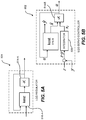
- FIG. 5A illustrates an example of an LQG regulator, in accordance with one or more embodiments.
- FIG. 5B illustrates an example of an LQG Servo Controller, in accordance with one or more embodiments of the present disclosure.
- FIG. 6 is a schematic illustration of an aircraft, in accordance with one or more embodiments of the present disclosure.
- FIG. 7 is a block diagram of aircraft production and service methodology that may utilize methods and assemblies described herein.
- a system uses a processor in a variety of contexts. However, it will be appreciated that a system can use multiple processors while remaining within the scope of the present disclosure unless otherwise noted.
- the techniques and mechanisms of the present disclosure will sometimes describe a connection between two entities. It should be noted that a connection between two entities does not necessarily mean a direct, unimpeded connection, as a variety of other entities may reside between the two entities.
- a processor may be connected to memory, but it will be appreciated that a variety of bridges and controllers may reside between the processor and memory. Consequently, a connection does not necessarily mean a direct, unimpeded connection unless otherwise noted.
- a combination of actuators may be implemented, including electromechanical actuators, electro-hydrostatic actuators, and electro-hydraulic servo actuators.
- electromechanical actuators including electromechanical actuators, electro-hydrostatic actuators, and electro-hydraulic servo actuators.
- electro-hydrostatic actuators including electro-hydraulic servo actuators.
- electro-hydraulic servo actuators including electromechanical actuators, electro-hydrostatic actuators, and electro-hydraulic servo actuators.
- force fighting which can create severe structural damage and or component failure over time if gone unaddressed. Force fighting in a system may be caused by differences in response between the two similar or dissimilar actuators operating on a common aircraft flight control surface.
- the systems and methods described herein provide an adaptive feedback control of force fighting in hybrid actuation systems, which is an innovative force fighting concept that provides optimum feedback compensation of actuator force fighting through the integration of Linear-Quadratic-Gaussian (LQG) control as well as the adaptive feed-forward compensation using Model Predictive Control (MPC).
- LQG Linear-Quadratic-Gaussian
- MPC Model Predictive Control
- These controllers implement look-ahead (previewing) on reference and measured disturbance trajectories. Regulation and tracking are achieved using look-ahead (previewing beyond the horizon) where position output tracks the reference command while rejecting force fight disturbances. Thus, the stability of a system is maintained, even under worst case input and output disturbances and noise.
- the disclosed methods and systems for adaptive feedback control of hybrid actuation systems ensures that the resulting force fight is negligible or limited to minimum acceptable limits, that the system is maintained with operating limits, and that the system is stable under any input/output disturbances and nose, and at any degraded conditions of the system.
- EHSA electro hydraulic servo-actuators
- EHA electro-hydrostatic actuators
- EMA electromechanical actuators
- Commercial airplanes are moving toward the implementation of hybrid actuation system to control primary and secondary flight control surface where the primary power source may be hydraulic and electric.
- FIG. 1 illustrates an example hybrid actuation system 100 , in accordance with one or more embodiments.
- system 100 may be implemented to move a control surface 102 .
- control surface 102 may be any one of various moveable parts of an aircraft, such ailerons, weapons systems, landing gear, etc., or a portion thereof.
- control surface 102 may be any one of various moveable parts of various other vehicles, including land and sea vehicles.
- System 100 may include one or more actuators that act on control surface 102 .
- system 100 includes actuators 110 and 120 .
- actuators 110 and 120 may act on control surface 102 to cause an angular displacement ⁇ d about an axis 104 .
- each one of actuators 110 and 120 may be any one of various actuators, including, but not limited to, an electro hydraulic servo-actuator (EHSA), electro-hydrostatic actuator (EHA), electromechanical actuator (EMA), etc.
- EHSA electro hydraulic servo-actuator
- EHA electro-hydrostatic actuator
- EMA electromechanical actuator
- an electro hydraulic servo-actuator (EHSA) may also be referred to as a servo-hydraulic actuator (SHA); these terms may be used interchangeably.
- system 100 is a hybrid actuation system comprising different actuator types, where actuator system 110 is an EHSA and actuator system 120 is an EHA.
- EHSA hydraulic actuators
- the mechanics of hydraulic actuators comprise of a pump that flows incompressible fluid into a hollow cylinder forcing a piston 118 to move inside of the hollow cylinder. As the pressure is increased, the piston 118 is likewise moved along the axis of that cylinder and creates a retracting linear force.
- a servo valve applied voltage u h may be applied to servo-valve drive electronics 112 of EHSA 110 , which produced valve current i v .
- the valve current i v operates servo valve 114 which utilizes hydraulic power from hydraulic power source 116 to operate a rod end 118 -A of EHSA 110 to produce an EHSA output force F h .
- an electrical actuator such as an EHA and EMA
- an electrical actuator entails conversion of the electric energy into torque by a mechanically-connected electric motor turning a hydraulic pump or thread lead-screw (ball screw or roller screw).
- an EHA applied voltage u e is applied to motor drive electronics 122 of EHA 120 , which provides electric power to a variable speed motor 124 to operate a fixed displacement hydraulic pump 126 .
- the screw rotates the nut is driven along the threads. The direction by which the nut moves is dependent upon the direction where the screw rotates, which likewise allows the actuator to extend or retract.
- the pump 126 may operate a rod end 128 -A of a piston 128 of EHA 120 to produce an EHA output force F e retracting the actuator. This may cause an EHA position function x e corresponding to the angular displacement ⁇ d .
- EHSA hydraulic
- EHA electrical actuator
- EMA electrical actuator
- Force Fighting may also be caused by the physical differences in power conversion and inertias between EHSA and electric actuator (EHA/EMA), the dynamics of these actuators are inherently different. This difference can lead to dynamic force fighting effects if operated on the same control surface.
- the spin up of the electric motor controlling the hydraulic pump or gearbox/lead-screw will cause the electric actuator to react slower to input changes.
- large inputs commands may create a conditions where the velocity of the electric actuator (EHA/EMA) exceeds the maximum velocity of the EHSA which is naturally limited.
- EHSA position transfer function X h and the EHA position transfer function X e may be determined by:
- X h x r - H 2 ⁇ ( s ) ⁇ F h H 1 ⁇ ( s )
- X e x r - E 2 ⁇ ( s ) ⁇ F e E 1 ⁇ ( s )
- x r is the position demand
- E 1 (s) is the input rejection function of the EHA
- E 2 (s) is the disturbance transfer function of the EHA
- H 1 (s) is input rejection function of the EHSA
- H 2 (s) is the disturbance transfer function of the EHSA.
- a mathematical description of the force fight dynamics may be provided using EHA transfer function X e and EHSA transfer function X h .
- the relationship between the input and output signals of the two actuators may be determined by:
- a force fight system in order to improve the system energy efficiency, reliability, and satisfy fatigue requirements, a force fight system has been developed that can be used in an active/active mode to satisfy the fatigue requirement (for the actuation load loop of fly-by-wire (FBW) actuation system).
- a force fight system may be used in an active/active actuation with redundant actuators operating on a common surface.
- FBW fly-by-wire
- FIG. 2 illustrates an example system 200 implementing a traditional approach to hybrid actuator systems, in accordance with one or more embodiments.
- system 200 may demonstrate a hybrid system including a SHA 110 and an EHA 120 acting on the surface of aileron 102 .
- An input command 240 is sent by signal processor 202 to the actuator controllers of SHA 110 and EHA 120 .
- the command 240 may cause a change in position 242 of the piston of SHA 110 at a particular rate 244 causing a corresponding change in position at aileron 102 at a corresponding rate.
- signal processor 202 may issue an input command 240 to cause a change in position 246 of the piston of EHA 120 at a particular rate 248 causing a corresponding change in position at aileron 102 at a corresponding rate.
- a SHA force 252 and EHA force 254 is applied to aileron 102 .
- differences in actuator operation may cause force fighting.
- the difference in output forces 252 and 254 may be measured and summed at 256 to determine the amount of force fighting.
- the measured force fighting, and the measured output forces 252 and 254 may then be transmitted to a user display 250 for monitoring.
- SHA 110 and EHA 120 may be configured in an open loop position in which SHA 110 and EHA 120 are uncoupled. In other embodiments, SHA 110 and EHA 120 may be configured in a closed loop position in which SHA 110 is slaved to the EHA pressure output via pressure slave 212 , such as shown in FIG. 2 . In some embodiments, system 200 may implement a proportional-integral-derivative (PID) controller to establish synchronization between actuators.
- PID proportional-integral-derivative
- synchronization between actuators in system 200 may be achieved using pressure sensor 222 from EHA 120 to equalize the pressure going into the actuator cylinder of SHA 110 via pressure slave 212 to match the output SHA position 242 and SHA rate 244 with the output EHA position 246 and EHA rate 248 .
- the output force 252 of SHA 110 and the output force 254 of EHA may be measured by sensors on aileron 102 .
- the output force from each actuator is additionally fed back into the respective actuator controllers to adjust the input command into each individual system to stabilize and correct the position of the aileron 102 .
- a closed loop scenario such as in system 200 shown in FIG. 2
- significant force fighting may occur during rise and fall times of aileron 102 , which may be more prominent at high output loading.
- static force fight may be suppressed; however, dynamic force fight may result from the delayed response of the SHA 110 when tracking the output pressure coming from the EHA 120 . If noise, loop disturbance, or high load is added to this scenario, both static and dynamic force fight are again created.
- the traditional approach of using PID compensators and controllers was found ineffective, resulting in worst case scenarios with static and dynamic force fight when dealing with noise and loop disturbances.
- Conventional PID systems may include two-degree-of-freedom (2-DOF) PID controllers that include set-point weighting on the proportional and derivative terms.
- a 2-DOF PID controller is capable of fast disturbance rejection without significant increase of overshoot in set-point tracking.
- 2-DOF PID controllers are also useful to mitigate the influence of changes in the reference signal on the control signal.
- the relationship between the 2-DOF controller's output and inputs can be represented in either feedforward or feedback PID configurations.
- the two forms differ in the parameters used to express the proportional, integral, and derivative actions of the controller.
- the disadvantage of these controllers are limited gain, bandwidth, and stability margins due to perturbations resulting from model parameter changes, high loads, noise, and disturbances
- an adaptive feed-forward compensation (AFFC) system may be implemented with integration of a Model Predictive Controller (MPC) and Linear Quadratic Gaussian (LQG) controller.
- MPC Model Predictive Controller
- LQG Linear Quadratic Gaussian
- FIG. 3A shown is an example adaptive feed-forward compensation (AFFC) system 300 , in accordance with one or more embodiments.
- system 300 may include multiple actuators, such as EHSA 110 and EHA 120 acting on aileron 102 .
- System 300 refines the traditional approach by enabling faster synchronization of the output position and force of the actuators so as to minimize force fighting.
- system 300 includes adaptive feedforward (FF) controllers 310 and 320 .
- system 300 may further comprise optimal gain feedback regulators 312 and 322 . As shown in FIG. 3A , feedforward controller 310 and feedback regulator 312 operate to adjust operation of EHSA 110 , while feedforward controller 320 and feedback regulator 322 operate to adjust operation of EHA 120 .
- FF adaptive feedforward
- a position command 330 may be transmitted from signal processor 302 to feedforward controllers 310 and 320 .
- feedforward controllers work on local feedback compensators accounting for compensating against the difference in static and dynamic forces between actuators 110 and 120 , which may be exasperated by one or more of the following: noise, disturbances, and output loading. These feed forward controllers may synchronize the positions and output forces from each actuator.
- An EHSA position command 332 -A may be issued from feedforward controller 310 to EHSA 110 .
- an EHA position command 332 -B may be issued from feedforward controller 320 to EHA 120 .
- the position commands 332 -A and 332 -B may be synchronized by corresponding feedforward controllers 310 and 320 such that actuators act on aileron 102 with appropriate positioning and rate to reduce force fighting.
- optimal gain feedback regulators are added as inner loop noise suppressors and plant disturbance compensators since the feedforward controllers may not operate fast enough to account for high frequency transient force fighting.
- the positioning of the actuators may be measured by sensors on the corresponding actuator.
- An EHSA position 334 -A may be determined at EHSA 110 and sent to feedback regulator 312 .
- An EHA position 334 -B may be determined at EHA 120 and sent to feedback regulator 322 .
- the force applied to aileron 102 by each actuator may also be measured by sensors located on aileron 102 .
- the EHSA force 336 -A may be determined at aileron 102 and sent to feedback regulator 312 .
- the EHA force 336 -B may be determined at aileron 102 and sent to feedback regulator 322 .
- the optimal gain feedback regulators require a command signal to force the output to state (0) when the output of the actuators are non-zero at the null position due to input noise or torque disturbances.
- the feedback regulators force use the measured states, as well as estimations for unmeasured states, to force the output to state (0).
- system 300 is able to reject fast dynamic transient force fighting by using digital filter and forward looking algorithms that anticipates and nulls position, force, and force fight transients.
- System 300 may also be implemented using conventional or predictive approach to achieve, stability, regulation, and tracking.
- PID compensators Traditional approach is normally implemented using PID compensators. However, these compensators have fixed bandwidth and gain margins. Thus, such PID compensators would not be able to quickly regulate a command signal to force the output of the actuators to state (0), which would require very high input energy that would destabilize traditional controllers if used.
- AFFC system 301 includes Model Predictive Controllers (MPC) as feedforward controllers, and optimal gain Linear Quadratic Gaussian (LQG) Controllers as feedback regulators.
- MPC 311 may be feedforward controller 310 and MPC 321 may be feedforward controller 320 .
- an LQG controller may comprise a linear quadratic regulator (LQR) and a Kalman filter.
- LQR linear quadratic regulator
- an LQR may also be referred to as an optimal gain compensator
- a Kalman filter may also be referred to as a Kalman estimator.
- an LQG controller comprising LQR 314 and Kalman filter 316 may be feedback regulator 312 .
- an LQG controller comprising LQR 324 and Kalman filter 326 may be feedback regulator 322 .
- System 301 may include actuators 110 -A and 120 -A controlling position of aileron 102 .
- actuators 110 -A and 120 -A may be any one of various actuator types, including hydraulic actuators such as an EHSA, or electric actuators such as an EHA or an EMA.
- actuator 110 -A may be an EHSA 110 and actuator 120 -A may be an EHA 120 .
- Each actuator. 110 -A and 120 -A may be controlled by an MPC and an LQG controller.
- actuator 110 -A is controlled by MPC 311 and an LQG that comprises LQR 314 and Kalman filter 316 .
- Actuator 120 -A is controlled by MPC 321 and an LQG comprising LQR 324 and Kalman filter 326 .
- actuators 110 -A and 120 -A may represent corresponding plant models of such actuators that calculates or predicts the process or behavior of the corresponding actuator, such as plant model 410 .
- plant models may be implemented within an MPC, as shown in FIGS. 4A and 4B .
- a plant model may exist separate from the MPC, as shown in FIG. 3B .
- the following description may be made with reference to the MPC and LQG system corresponding to one actuator.
- each actuator system in system 301 may include substantially similar configurations.
- Synchronization and tracking between actuators are achieved in system 301 using the MPCs.
- Feedback compensation via the LQGs with integral gains may work on local feedback accounting for compensating against the difference in static forces between actuators.
- the LQGs may account for filtering fast dynamic transient noise using a Kalman estimator, a Linear-quadratic Regulator (LQR), and a local MPC that anticipates and nulls force fighting transients to provide optimal local output parameters y(k).
- LQR Linear-quadratic Regulator
- the position command r(k) is fed into the system to be used by the actuators as a reference.
- the outputs of the actuators may be expected to be in sync, regulated, and tracking. However, due to measurement noise and torque disturbances, their outputs may be randomly different, resulting in force fighting. In a system where the actuators are not the same (different technology and power sources), the difference in outputs would be greater and result in dynamic and constant force fighting.
- system 301 may be configured in an open loop or closed loop configuration, as previously described. As shown in FIG. 3B , system 301 is in a closed loop configuration in which slaved switch 340 is implemented to connect the output y(k) of actuator 110 -A to the input of actuator 120 -A. In an open loop configuration, the slave switch 340 will be implemented to directly feed input command r(k) to actuator 120 -A.
- MPCs are used to synchronize the actuators, track the position command r(k), widen stability margins, and to supervise the system as a whole.
- a position command r(k) may be input into MPC 311 as a reference command or input command.
- MPC 311 may use position command r(k) to determine a future manipulated variable u(k) at control interval k for operation of actuator 110 -A.
- the measured local output parameters y(k) measured from actuator 110 -A are used as feedback that is input to one or more of the MPCs and may include parameters, such as, position, force, force fight, etc.
- measured disturbances v(k) may be subtracted from actuator output y a (k) measured at actuator 110 -A to determine local output parameters y(k).
- measured local output parameters y(k) may be determined by subtracting measured disturbances v(k), such as torque disturbances, from the predicted output y p (k) determined by a plant model corresponding to actuator 110 -A at 362 .
- a plant model corresponding to actuator 110 -A may be plant model 410 , further described with reference to FIG. 4A .
- Input noise w(k) may also be input into the MPC, such as MPC 311 .
- Input noise w(k) may be any unwanted energy into the system, i.e. electrical noise, thermal, or mechanical.
- input noise w(k) may be white noise, which is Gaussian, and its power spectral density is nearly equal throughout the frequency range of the system.
- Input noise w(k) is further described with reference to FIGS. 4A and 4B . Since the MPC 311 is an optimal predictive controller, it finds the best control parameter vector ⁇ U for the future manipulated variable u(k) at control interval k, such that an error function between the set-point, r(k), and the predicted output, y p (k), is minimized.
- the cost function J reflects the control objective to bring the predicted output Y as close as possible to the set-points R s .
- (R s ⁇ Y) T is a transposed matrix.
- ⁇ R is a diagonal matrix used as a tuning matrix such that if set to zero, then J would solely make the error (R s ⁇ Y) T (R s ⁇ Y) as small as possible without regard to how large the ⁇ U is.
- LQR 314 takes the future manipulated variable u(k) as input.
- Input noise w(k) may also be added to the future manipulated variable u(k) at 360 before being input into LQR 314 .
- x est (k) is an estimate of the full state vector x(k) determined by a Kalman filter, such as Kalman filter 316 .
- Such state feedback law minimizes the quadratic cost function described below with reference to Equation 3. This may specify the tradeoff between performance and cost of control.
- the adjusted manipulated variable u LQR (k) may be fed to actuator 110 -A.
- LQR 314 requires a full state vector to function.
- a Kalman estimator 316 may be used to estimate the full state vector, x(k), as x est (k). Therefore, when the other parameters cannot be measured, the Kalman estimator 316 gives a full estimate of the parameters.
- at least one measured parameter is required to minimize the cost function, or the asymptotic covariance of the error function x(k) ⁇ x est (k).
- the adjusted future manipulated variable u LQR (k), and/or the measured local output parameters y(k) may be input into the Kalman estimator to determine x est (k).
- the LQG controller may comprise a combination of the LQR and the Kalman estimator.
- MATLAB which may also be referred to herein as Matlab, is a programming language that provides a multi-paradigm numerical computing environment. In various other embodiments, other appropriate programming language may be implemented to construct the LQG controller.
- MPC Model Predictive Controller
- FIGS. 4A and 4B illustrate an example Model Predictive Control (MPC) system 400 , in accordance with one or more embodiments.
- FIG. 4A depicts a general flow process of a feed-forward control by MPC system 400 on an actuator, such as actuator 110 or 120 .
- FIG. 4B depicts the input variables within the flow process of a feed-forward control by MPC system 400 on an actuator 110 .
- a Model Predictive Control such as MPC 400
- MPC 400 is an advanced, multi-variable, digital control technology that has an internal dynamic model that can predict components behavior of a plant model in the near future.
- An MPC may also be referred to herein as a receding horizon control.
- MPC 400 may include an optimizer 462 and a plant model 410 corresponding to actuator 110 .
- MPC 400 integrates feed-forward control to reject measured disturbances 466 and acts as a compensator signal until the system can meet the desired trajectory (including rate and position).
- MPC 400 may receive various inputs, including references 460 (such as an input command) and measured disturbances 466 which may be measured by various sensors. Other inputs may be included in references 460 and used as input for MPC 400 .
- an MPC may utilize such inputs to construct and solve a constrained optimization problem using optimizer 462 . Only the first optimal control move is applied in the plant (actuator 110 ). Additionally, measurements 468 may be made at the actuator, or other part, such as an aileron, to determine the force applied to the part by the actuator. Such measurements 468 may be fed back to MPC 400 ) as additional input. This process is repeated at control interval k+1 and so on. Thus, the prediction horizon of a given MPC is shifting forward.
- the general design objective of model predictive control by an MPC 400 is to compute a trajectory of a future manipulated variable, u(k), at a particular time interval k, to optimize the future behavior of the plant output, y(k).
- An MPC using the information derived from the plant model or actuator, may predict what may happen (model), measures the actuator output (measurement) and implements planned activities to obtain the desired trajectories (realization of control).
- controller performance may be evaluated.
- controller performance may be adjusted as it runs by tuning weights (i.e. cost function J) and varying constraints. This may be implemented by an optimizer, such as 462 .
- optimizer 462 constraints may be set on the lower and upper bounds of the manipulated variable and the plant output variable, y(k).
- the adaptive model predictive controllers may be implemented by updating the plant model at run time. For applications with fast sample times, explicit model predictive controllers can be developed. For rapid prototyping and embedded system design, the MATLAB MPC toolbox supports C-code and IEC 61131-3 Structured Text generation.
- an MPC 400 may use plant, disturbance, and noise models for prediction and state estimation. As shown in FIG. 4B , MPC 400 may include plant model 410 , input disturbance model 420 , output disturbance model 430 , and measurement noise model 440 .
- x c (k+1) is the state variable controller vector at interval k+1
- u o (k) is the input variable (or manipulated variable)
- y(k) is the process output.
- A, B, C, and D are constant state-space matrices that represent the plant model.
- x c is the controller state which comprises n xp +n xid +n xod +n xn state variables.
- the plant model state vector, of length n xp , of plant model 410 is represented by the variable, x p .
- the input disturbance model state vector, of length n xid , of input disturbance model 420 is represented by the variable, x id .
- the output disturbance model state vector, of length n xod , of output disturbance model 430 is represented by the variable x od .
- the measurement noise model state vector, of length n xn of measurement noise model 440 is represented by the variable, x n .
- u o T (k) [ u T ( k ) v T ( k ) w id T ( k ) w od T ( k ) w n T ( k )]
- the input variables of u o include manipulated variable vector u, measured disturbance vector v, input disturbance white noise vector w id , output disturbance white noise vector w od , and measurement noise model white noise vector w n .
- Manipulated variables are adjusted by MPC 400 to achieve synchronization between actuators. Measured disturbances cannot be adjusted by MPC 400 , but are utilized by MPC 400 for feedforward compensation.
- x p (k+1) is the future state variable of the plant model
- u p (k) represents the aggregate input variables into plant model 410
- y p (k) is the predicted output of the plant model.
- inputs u p (k) into plant model 410 are independent variables, and may include manipulated variables u(k), measured disturbances v(k), and unmeasured disturbances d(k).
- MPC 400 may not have direct knowledge of unmeasured input disturbances d(k), but can compensate for it based on disturbance models.
- unmeasured input disturbances d(k) may be determined by input disturbance model 420 using input disturbance white noise vector w id (k).
- white noise vector w id (k) may correspond to a general representation of noise originating and coming into the system. AS with w(k), this noise may be represented as Gaussian, with power spectral density nearly equal throughout the systems frequency spectrum.
- the input disturbance white noise vector w id (k) is input into input disturbance model 420 .
- Input disturbance model 420 may specify the signal type and characteristics of the input disturbance.
- outputs of plant model 410 are dependent variables, and may include predicted outputs y p (k), measured outputs y(k), and unmeasured outputs, y u (k). Measured outputs y(k) may be determined from summing predicted outputs y p (k) and unmeasured output disturbances y od (k) at 450 . In some embodiments, measured disturbances v(k), such as torque disturbances, may also be subtracted from the predicted outputs y p (k) at 450 .
- the output disturbance model 430 may specify the signal type and characteristics of the output disturbance.
- w od (k) represents the output disturbance white noise vector that is input into output disturbance model 430 .
- Measured outputs y(k) may be used to estimate unmeasured quantities and feedback designated by unmeasured outputs y u (k) which may be estimated by MPC 400 based on available measurements and other outputs of plant model 410 .
- unmeasured outputs y u (k) may be the difference between predicted outputs y p (k) and measured outputs y(k) at 450 .
- y u (k) y m (k) ⁇ y n (k) at 452 .
- the measured outputs y(k) may be added to the noise signal output y n (k) determined by the measurement noise model 440 at 452 to determine a measured output y m (k).
- Output y u (k) may also be an unmeasured output, y a (k) from an actuator 110 .
- y a (k) may also include other unmeasured output variables for which the system does not have a means of direct (sensor) measurements.
- the measurement noise model 440 specifies the measurement noise signal type and characteristics.
- u is the manipulated variable or input variable into the plant models
- y is the process output
- x c is the state variable vector
- u(k) represents the trajectory to optimize the desired output
- ⁇ u(k) u(k) ⁇ u(k ⁇ 1)
- the augmented state-state model for x and y may be:
- ⁇ ⁇ ⁇ ⁇ x c ⁇ ( k + 1 ) A c ⁇ ⁇ ⁇ ⁇ x c ⁇ ( k ) + B c ⁇ ⁇ ⁇ ⁇ u ⁇ ( k ) Equation ⁇ ⁇ 1.3
- x(k+1) f(x(k)); u(k), an input u(k) is determined at each time slot k based on x(k).
- the input may be selected as to minimize predicted costs over the planning horizon k, k+1, . . . k+N.
- N is the length of the planning horizon.
- the predicted control trajectory may be determined by using Equations 1.3 and 1.4, to find the augmented state-state model as:
- the predicted future control trajectory may be given by: ⁇ u ( k i ), ⁇ u ( k i +1), . . . ⁇ u ( k i +N c ⁇ 1) where N c is the control time interval.
- the future state variables may be given by: x ( k i +1
- the predicted output variables are, by substitution: y ( k i +1
- k i ) CAx ( k i )+ CB ⁇ u ( k i ) y ( k i +2
- k i ) CA 2 x ( k i )+ CAB ⁇ u ( k i )+ CB ⁇ u ( k i +1) y ( k i +3
- k i ) CA 3 x ( k i )+ CA 2 B ⁇ u ( k i )+ CAB ⁇ u ( k i +1)+ CB ⁇ u ( k i +2) . . .
- k i )] T ⁇ U [ ⁇ u ( k i ) ⁇ u ( k i +1) ⁇ u ( k i +2) . . .
- the objective of the predictive control system is to bring the predicted output as close as possible to the set-point signal.
- the optimal control parameter vector ⁇ U may be found such that an error function between the set-point and the predicted output is minimized.
- J ( R s ⁇ Fx ( k i )) T ( R s ⁇ Fx ( k i )) ⁇ 2 ⁇ U T ⁇ T ( R s ⁇ Fx ( k i ))+ ⁇ U T ( ⁇ T ⁇ + ⁇ R ) ⁇ U
- ⁇ U ( ⁇ T ⁇ + ⁇ R ) ⁇ 1 ⁇ T ( R s ⁇ Fx ( k i ))
- ( ⁇ T ⁇ + ⁇ R ) ⁇ 1 ⁇ T R s corresponds to the set-point change
- ⁇ ( ⁇ T ⁇ + ⁇ R ) ⁇ 1 ⁇ T F corresponds to the state feedback control within the framework of predictive control.
- Linear-Quadratic Gaussian Controller Linear-Quadratic Regulator
- a Linear Quadratic Gaussian controller is servo controller which operates an LQR with a Kalman filter.
- an LQG may include LQR 314 and Kalman filter 316 .
- an LQG may include LQR 324 and Kalman filter 326 .
- an LQG controller may be integrated with an MPC in an AFFC system comprising hybrid (EHA/EHSA) or dual (EMA/EMA) actuator systems operating on a common control surface.
- EHA/EHSA hybrid
- EMA/EMA EMA
- an LQR is an optimal gain (K) regulator that forces the output u LQR (k) to state (0).
- the cost function may be given by:
- the payment is quadratic for both state and control effort.
- the time horizon, T or N, is often taken as ⁇ .
- the weights Qx, Qi, and R are the tuning knobs.
- N is an additional type of cost term, 2x(t)0Nu(t).
- ⁇ K is the state feedback gain matrix
- S is the solution of the algebraic Riccati equation
- e is the resulting closed loop eigenvalues (i.e. the eigenvalues of A ⁇ BK). In practice this is often the preferred way of deriving an initial controller before making finer refinements (based on simulations and tests).
- u ( t ) ( ⁇ R ⁇ 1 B′P ( t )) x ( t )
- P(t) is the solution of a Riccati differential equation.
- u ( k ) ( ⁇ ( R+B′P ( k+ 1) B ) ⁇ 1 B′P ( k+ 1) A ) x ( k )
- the n-by-n matrix P(k) is the solution of a Riccati difference equation.
- LQR may be used for tracking some desired trajectory, ⁇ x( ).
- this trajectory is a non-zero desired constant set point, ⁇ x.
- the solution for desired trajectories may be presented as a separate problem, such as an open-loop optimal control that is based on calculus of variations.
- x c (k+1) Ax c (k)+Bu o (k)
- the value for x can be estimated for a full state vector X and taking into account disturbance and noise vectors.
- the estimation may be performed as follows:
- Step 6 the covariance process is updated with: P k ⁇ ( I ⁇ KH ) P kp
- Step 7 returns to Step 1 for subsequent iterations where x c (k) ⁇ x c (k ⁇ 1), and P kp ⁇ P k-1 .
- a Kalman Filter may be implemented.
- a Kalman Filter may describe an optimal estimator used when dealing with Gaussian white noise.
- L is the Kalman Gain
- P is the covariance matrix
- w and v are modelled as white noise.
- the software may then generate the estimate using the following:
- u corresponds to the controls
- y corresponds to measurements.
- Qn E ( ww T )
- Rn E ( vv T )
- Nn E ( wv T )
- FIG. 5A illustrates an example of an LQG regulator 501 , in accordance with one or more embodiments.
- LQG regulator 501 comprises LQR 514 -A and Kalman estimator 516 -A.
- LQR 514 -A may be LQR 314 or 324 .
- Kalman filter 516 -A may be Kalman filter 316 or 326 .
- the LQG may be formed by combining them.
- MATLAB may be used to form the LQG regulator.
- This command forms the LQG regulator as shown in FIG. 5A .
- the configuration shown in FIG. 5A ensures that the output y(k) of the actuator is at state (0).
- FIG. 5B illustrates an example of an LQG servo controller 502 , in accordance with one or more embodiments.
- LQG servo controller 502 comprises LQR 514 -B and Kalman estimator 516 -B.
- LQR 514 -B may be LQR 314 or 324 .
- Kalman filter 516 -B may be Kalman filter 316 or 326 .
- LQG servo controller 502 may further comprise integrator 520 .
- This command forms the LQG regulator as shown in FIG. 5B .
- the configuration shown in FIG. 5B ensures that the output y(k) of the actuator tracks the reference command r(k) while rejecting input noise w(k) and torque disturbance v(k).
- the system 301 represents an example of an MPC-LQR Model with feed-forward and feedback compensation, in accordance with one or more embodiments.
- This system 301 demonstrates the optimum feedback compensation using LQRs, as well as the adaptive feedforward compensation using MPCs.
- feedback compensation is achieved using Linear Quadratic Gaussian Servo Controller for each actuator and feedforward compensation is achieved using the MPCs.
- This system further demonstrates the optimum feedback compensation between the SHA and the EHA on the aileron.
- feedback compensation is achieved using Linear Quadratic Gaussian Servo Controller for each actuator.
- the servo controller ensures that the position output tracks the reference command while rejecting force fight disturbances.
- This system demonstrates the force fighting feedback compensation between a servo-hydraulic actuator (SHA) and an electro-hydraulic actuator (EHA) on an aileron surface.
- force fighting feedback compensation is achieved using MPCs for each actuator. As shown, each MPC controller is applied locally to the respective actuator. The main controls for the position commands of an actuator are the manipulated variables of the MPC.
- the outputs of an actuator are then fed back into the plant's inner loop compensators and the MPC.
- force fighting output is fed back into the MPCs as measured disturbance inputs. This influences the dynamic response when the measured force fighting deviates from zero. If the disturbance model predicts a sustained value, MPC adjustments will continue until the plant output returns to zero. Thus, the MPC ensures that the system is maintained within operating limits for a very wide variation of force fighting errors.
- FIG. 6 is a schematic illustration of aircraft 600 , in accordance with some embodiments.
- aircraft 600 is defined by a longitudinal axis (X-axis), a lateral axis (Y-axis), and a vertical axis (Z-axis).
- aircraft 600 comprises airframe 650 with interior 670 .
- Aircraft 600 includes wings 620 coupled to airframe 650 .
- Aircraft 600 may also include engines 630 supported by wings 620 .
- aircraft 600 further includes a number of high-level inspection systems such as electrical inspection system 640 and environmental inspection system 660 . In other embodiments, any number of other inspection systems may be included.
- Aircraft 600 shown in FIG. 6 is one example of a vehicle of which components may be fabricated, modified, or machined to include at least one of systems 100 , 200 , 300 , and 301 , in accordance with illustrative embodiments.
- an aerospace example is shown, the principles disclosed herein may be applied to other industries, such as the automotive industry. Accordingly, in addition to aircraft 600 , the principles disclosed herein may apply to other vehicles, e.g., land vehicles, marine vehicles, space vehicles, etc.
- illustrative method 700 may include specification and design (block 704 ) of aircraft 600 and material procurement (block 706 ).
- material procurement block 706
- component and subassembly manufacturing block 708
- inspection system integration block 710
- Described devices and assemblies, and corresponding methods, can be used in any of specification and design (block 704 ) of at least one of aircraft 600 , material procurement (block 706 ), component and subassembly manufacturing (block 708 ), and inspection system integration (block 710 ) of aircraft 600 .
- aircraft 600 may go through certification and delivery (block 712 ) to be placed in service (block 714 ). While in service, aircraft 600 may be scheduled for routine maintenance and service (block 716 ). Routine maintenance and service may include modification, reconfiguration, refurbishment, etc. of one or more inspection systems of aircraft 600 . Described devices and assemblies, and corresponding methods, can be used in any of certification and delivery (block 712 ), service (block 714 ), and routine maintenance and service (block 716 ).
- Each of the processes of illustrative method 700 may be performed or carried out by an inspection system integrator, a third party, or an operator (e.g., a customer).
- an inspection system integrator may include, without limitation, any number of aircraft manufacturers and major-inspection system subcontractors;
- a third party may include, without limitation, any number of vendors, subcontractors, and suppliers;
- an operator may be an airline, leasing company, military entity, service organization, and so on.
- System(s), apparatus(es), and corresponding method(s) shown or described herein may be employed during any one or more of the stages of manufacturing and service method (illustrative method 700 ).
- components or subassemblies corresponding to component and subassembly manufacturing (block 708 ) may be fabricated or manufactured in a manner similar to components or subassemblies produced while aircraft 600 is in service (block 714 ).
- one or more examples of the system(s), apparatus(es), method(s), or combination thereof may be utilized during production stages (block 708 ) and (block 710 ), for example, by substantially expediting assembly of or reducing the cost of aircraft 600 .
- one or more examples of the systems, apparatus, or method realizations, or a combination thereof may be utilized, for example and without limitation, while aircraft 600 is at least one of in service (block 714 ) and during maintenance and service (block 716 ).
Landscapes
- Engineering & Computer Science (AREA)
- Automation & Control Theory (AREA)
- Aviation & Aerospace Engineering (AREA)
- Physics & Mathematics (AREA)
- Computer Vision & Pattern Recognition (AREA)
- Medical Informatics (AREA)
- Software Systems (AREA)
- Evolutionary Computation (AREA)
- General Physics & Mathematics (AREA)
- Health & Medical Sciences (AREA)
- Artificial Intelligence (AREA)
- Fluid Mechanics (AREA)
- Feedback Control In General (AREA)
- Servomotors (AREA)
Abstract
Description
where xr is the position demand; E1(s) is the input rejection function of the EHA; E2(s) is the disturbance transfer function of the EHA; H1(s) is input rejection function of the EHSA; H2(s) is the disturbance transfer function of the EHSA.
J=(R s −Y)T(R s −Y)+ΔU T
u LQR(k)=−Kx est(k)
where xest(k) is an estimate of the full state vector x(k) determined by a Kalman filter, such as
x c(k+1)=Ax c(k)+Bu o(k) Equation 1:
y(k)=Cx c(k)+Du o(k) Equation 2:
Here, xc(k+1) is the state variable controller vector at interval k+1, uo(k) is the input variable (or manipulated variable), and y(k) is the process output. A, B, C, and D are constant state-space matrices that represent the plant model.
x c T(k)=[x p T(k)x id T(k)x od T(k)x n T(k)]
u o T(k)=[u T(k)v T(k)w id T(k)w od T(k)w n T(k)]
x p(k+1)=A p x p(k)+BS i u p(k)
y p(k)=S o −1 Cx p(k)+S o −1 DS i u p(k)
x id(k+1)=A id x id(k)+B id w id(k)
d(k)=C id x id(k)+D id w id(k)
x od(k+1)=A od x od(k)+B od w od(k)
y od(k)=C od x od(k)+D od w od(k)
x n(k+1)=A n x n(k)+B n w n(k) Equation 1:
y n(k)=C n x n(k)+D n w n(k) Equation 2:
x c(k+1)=A c x c(k)+B c u(k)
y(k)=C c x c(k)
y(k)=C c x c(k)+D c u(k)
Δu(k i),Δu(k i+1), . . . Δu(k i +N c−1)
where Nc is the control time interval.
x(k i+1|k i),x(k i+2|k i), . . . ,x(k i +m|k i), . . . ,x(k i +N p |k i)
where Np is the prediction time interval.
y(k i+1|k i)=CAx(k i)+CBΔu(k i)
y(k i+2|k i)=CA 2 x(k i)+CABΔu(k i)+CBΔu(k i+1)
y(k i+3|k i)=CA 3 x(k i)+CA 2 BΔu(k i)+CABΔu(k i+1)+CBΔu(k i+2)
. . .
y(k i +N p |k i)=CA N
Y=[y(k i+1|k i)y(k i+2|k i)y(k i+3|k i) . . . y(k+N p |k i)]T
ΔU=[Δu(k i)Δu(k i+1)Δu(k i+2) . . . Δu(k i +N c−1)]T
where in the single-input and single-output case, the dimension of Y is Np and the dimension of ΔU is Nc. A compact matrix may be formed as Y=Fx(ki)+ΦΔU.
where
J=(R s −Y)T(R s −Y)+ΔU T− RΔU
where Rs is a data vector containing the set-point information, and R is a diagonal matrix in the form of
R=r w IN c ×N c(r w≥0)
where rw is a tuning parameter for the desired closed-loop performance.
J=(R s −Fx(k i))T(R s −Fx(k i))−2ΔU TΦT(R s −Fx(k i))+ΔU T(ΦTΦ+−R)ΔU
ΔU=(ΦTΦ+−R)−1ΦT(R s −Fx(k i))
where (ΦTΦ+−R)−1ΦTRs corresponds to the set-point change, while −(ΦTΦ+−R)−1ΦTF corresponds to the state feedback control within the framework of predictive control.
J(u)=∫0 ∞(x T Qx+u T Ru+2x T Nu)dt Equation 3:
J(u)=∫0 T(x(t)′Qx(t)+u(t)′Ru(t))dt+x(T)′Q f x(T)
Here Q is a state weighting matrix, R is a control weighting matrix, and the time horizon T or N may be finite or infinite.
[K,S,e]=lqr(SYS,Q,R,N)
u(t)=(−R −1 B′P(t))x(t)
Here, the n-by-n matrix P(t) is the solution of a Riccati differential equation.
−{dot over (P)}(t)=A′P(t)+P(t)A−P(t)BR −1 B′P(t)+Q,P(T)=Q f
0=A′P+PA−PBR −1 B′P+Q
u(t)=(−R −1 B′P(t))x(t), or
u(t)=(−R −1 B′P)x(t)
u(k)=(−(R+B′P(k+1)B)−1 B′P(k+1)A)x(k)
Here, the n-by-n matrix P(k) is the solution of a Riccati difference equation.
P(k)=Q+A′P(k+1)A−A′P(k+1)B(R+B′P(k+1)B)−1 B′P(k+1)A,P(N)=Q f
P=Q+A′PA−A′PB(R+B′PB)−1 B′PA
u(k)=(−(R+B′P(k+1)B)−1 B′P(k+1)A)x(k), or
u(k)=(−(R=B′PB)−1 B′PA)x(k)
J
x c(k p)=A c x c(k−1)+B c u(k)+w(k)
P kp =A c p k-1 A c T +Q k
K=P kp H T/(HP kp H T +R)
where R is the sensor noise covariance matrix.
Y k =C c Y kc +Z k
x c(k)=x c(k p)+KG[Y k −Hx c(k p)]
P k−(I−KH)P kp
[kest,L,P]=Kalman(sys,Qn,Rn,Nn)
x(est)=Ax+Bu+Gw
y=Cx+Du+Hw+v
Qn=E(ww T),Rn=E(vv T),Nn=E(wv T)
with an estimation error, x−x(est).
regulator=lqgreg(kest,K)
servocontroller=lqgtract(kest,K)
Claims (30)
Priority Applications (7)
| Application Number | Priority Date | Filing Date | Title |
|---|---|---|---|
| US15/799,724 US10759519B2 (en) | 2017-10-31 | 2017-10-31 | Adaptive feedback control of force fighting in hybrid actuation systems |
| CA3010063A CA3010063C (en) | 2017-10-31 | 2018-06-28 | Adaptive feedback control of force fighting in hybrid actuation systems |
| CN201810834257.5A CN109725527B (en) | 2017-10-31 | 2018-07-26 | Drive controller unit |
| EP24159551.1A EP4350452A3 (en) | 2017-10-31 | 2018-08-08 | Adaptive feedback control of force fighting in hybrid actuation systems |
| EP18187997.4A EP3476724A3 (en) | 2017-10-31 | 2018-08-08 | Adaptive feedback control of force fighting in hybrid actuation systems |
| JP2018199480A JP7211759B2 (en) | 2017-10-31 | 2018-10-23 | Adaptive Feedback Control of Force Fighting in Hybrid Actuation Systems |
| BR102018071786-3A BR102018071786B1 (en) | 2017-10-31 | 2018-10-23 | DRIVE CONTROLLER UNIT, AIRCRAFT AND FORCE CONFLICT COMPENSATION SYSTEM |
Applications Claiming Priority (1)
| Application Number | Priority Date | Filing Date | Title |
|---|---|---|---|
| US15/799,724 US10759519B2 (en) | 2017-10-31 | 2017-10-31 | Adaptive feedback control of force fighting in hybrid actuation systems |
Publications (2)
| Publication Number | Publication Date |
|---|---|
| US20190127049A1 US20190127049A1 (en) | 2019-05-02 |
| US10759519B2 true US10759519B2 (en) | 2020-09-01 |
Family
ID=63490148
Family Applications (1)
| Application Number | Title | Priority Date | Filing Date |
|---|---|---|---|
| US15/799,724 Active 2038-10-30 US10759519B2 (en) | 2017-10-31 | 2017-10-31 | Adaptive feedback control of force fighting in hybrid actuation systems |
Country Status (5)
| Country | Link |
|---|---|
| US (1) | US10759519B2 (en) |
| EP (2) | EP3476724A3 (en) |
| JP (1) | JP7211759B2 (en) |
| CN (1) | CN109725527B (en) |
| CA (1) | CA3010063C (en) |
Cited By (4)
| Publication number | Priority date | Publication date | Assignee | Title |
|---|---|---|---|---|
| US20210191281A1 (en) * | 2018-07-04 | 2021-06-24 | Canon Kabushiki Kaisha | Control apparatus, exposure apparatus, and method of manufacturing article |
| US11326628B2 (en) * | 2019-12-09 | 2022-05-10 | The Boeing Company | Hydraulic actuation system for imparting rotation |
| US11358730B1 (en) | 2021-11-12 | 2022-06-14 | Beta Air, Llc | Systems and methods for an aircraft motion observer in an electric aircraft |
| US12151804B2 (en) | 2021-01-18 | 2024-11-26 | Goodrich Actuation Systems Sas | Actuator control for force fight mitigation |
Families Citing this family (22)
| Publication number | Priority date | Publication date | Assignee | Title |
|---|---|---|---|---|
| FR3061136B1 (en) * | 2016-12-23 | 2019-05-24 | Safran Electronics & Defense | ELECTROMECHANICAL MOBILE FLYING SURFACE ACTUATOR |
| JP7003623B2 (en) * | 2017-12-15 | 2022-01-20 | オムロン株式会社 | Control system |
| JP6958574B2 (en) * | 2018-01-11 | 2021-11-02 | オムロン株式会社 | How to set control parameters for model predictive control |
| US10668931B2 (en) * | 2018-08-16 | 2020-06-02 | Mitsubishi Electric Research Laboratories, Inc. | Controlling system subject to partially hidden actuator dynamics |
| RU2734153C1 (en) * | 2019-06-28 | 2020-10-13 | Акционерное общество "Российская самолетостроительная корпорация "МиГ" (АО "РСК "МиГ") | Non-linear correcting device for automatic control systems |
| US11486477B2 (en) | 2019-09-10 | 2022-11-01 | The Boeing Company | System and method for monitoring the remaining useful life of a ball screw in actuation system |
| US11644814B2 (en) | 2019-11-20 | 2023-05-09 | Abb Schweiz Ag | Method and apparatus for coordinating the utilization of operational zones to achieve production goals |
| US10988237B1 (en) * | 2019-12-17 | 2021-04-27 | The Boeing Company | Feed forward equalization control for active-active redundant actuation systems |
| CN111196560B (en) * | 2020-01-03 | 2020-10-20 | 山东大学 | Method and system for dynamically adjusting dangerous area range of bridge crane |
| EP3916646A1 (en) * | 2020-05-29 | 2021-12-01 | Atos Information Technology GmbH | Adaptive machine learning system for an edge device |
| ES2969875T3 (en) * | 2020-07-09 | 2024-05-23 | Airbus Defence And Space Sau | Control system and method of an actuator for an aircraft flight control surface |
| US11987344B2 (en) * | 2020-07-13 | 2024-05-21 | Embraer S.A. | Rudder system architecture for electrical actuators |
| CN114442601B (en) * | 2020-11-06 | 2024-06-18 | 宇通客车股份有限公司 | A method and device for tracking and controlling an unmanned vehicle |
| CN113110051B (en) * | 2021-04-14 | 2022-03-04 | 南开大学 | Polishing machine manpower/position hybrid control method and system considering error constraint |
| CN113296404B (en) * | 2021-05-21 | 2025-01-28 | 重庆大学 | Electric steering gear control system and control method |
| CN113867155B (en) * | 2021-11-10 | 2023-05-26 | 中国科学院光电技术研究所 | Disturbance identification and self-adaptive compensation method suitable for photoelectric tracking system |
| CN114280932B (en) * | 2021-12-14 | 2023-11-10 | 中国运载火箭技术研究院 | An integrated control method for vehicle posture and attitude considering the dynamic characteristics of the servo mechanism |
| US12368401B1 (en) * | 2022-04-08 | 2025-07-22 | Brunswick Corporation | Electric linear actuator with position sensing |
| CN116969331B (en) * | 2023-09-21 | 2023-12-12 | 华侨大学 | Five-time polynomial smooth self-defined track precision parallel crane |
| CN118447610A (en) * | 2024-06-18 | 2024-08-06 | 深圳市颖特新科技有限公司 | Intelligent door lock control method and device based on multidimensional sensor |
| CN119937321B (en) * | 2025-02-13 | 2025-10-17 | 国家石油天然气管网集团有限公司 | High-precision torque control method based on improved feedforward inverse compensation and adaptive control |
| CN120161716B (en) * | 2025-03-14 | 2025-11-18 | 东北大学 | Pipeline model prediction control method and system based on aeroengine |
Citations (14)
| Publication number | Priority date | Publication date | Assignee | Title |
|---|---|---|---|---|
| US6052647A (en) * | 1997-06-20 | 2000-04-18 | Stanford University | Method and system for automatic control of vehicles based on carrier phase differential GPS |
| US6208914B1 (en) * | 1996-11-21 | 2001-03-27 | Barron Associates, Inc. | System for improved receding-horizon adaptive and reconfigurable control |
| US20040159100A1 (en) * | 2001-05-10 | 2004-08-19 | Guy Bernard | Apparatus for coupling force-activated actuators |
| US20060064291A1 (en) * | 2004-04-21 | 2006-03-23 | Pattipatti Krishna R | Intelligent model-based diagnostics for system monitoring, diagnosis and maintenance |
| US20100268353A1 (en) * | 2007-12-21 | 2010-10-21 | Crisalle Oscar D | Systems and Methods for Offset-Free Model Predictive Control |
| US20110089884A1 (en) * | 2009-10-15 | 2011-04-21 | Harke Michael C | Multi-actuator motion control system |
| US20110108671A1 (en) | 2009-11-09 | 2011-05-12 | Honeywell International Inc. | Flight control surface actuation force fight mitigation system and method |
| US8245967B2 (en) | 2008-11-25 | 2012-08-21 | The Boeing Company | Actuator force equalization controller |
| US20130158680A1 (en) * | 2011-12-20 | 2013-06-20 | Pratt & Whitney | Hybrid Control System |
| CN104265708A (en) | 2014-09-04 | 2015-01-07 | 北京航空航天大学 | Self-adaption decoupling control method based on motion state synchronization |
| US9397587B2 (en) | 2013-11-20 | 2016-07-19 | Massachusetts Institute Of Technology | Multi-actuator design and control for a high-speed/large-range nanopositioning system |
| US20170283040A1 (en) * | 2016-03-30 | 2017-10-05 | Goodrich Actuation Systems Sas | Force fight mitigation |
| US20170349267A1 (en) * | 2016-06-01 | 2017-12-07 | Regents Of The University Of Minnesota | Fault-tolerant aircraft flight control using a subset of aerodynamic control surfaces |
| US20180362149A1 (en) * | 2017-06-14 | 2018-12-20 | The Boeing Company | Methods and apparatus for controlling aircraft flight control surfaces |
Family Cites Families (7)
| Publication number | Priority date | Publication date | Assignee | Title |
|---|---|---|---|---|
| JP3490561B2 (en) * | 1995-11-27 | 2004-01-26 | カヤバ工業株式会社 | Servo control system |
| CN101339406B (en) * | 2007-07-04 | 2011-05-11 | 中国科学院自动化研究所 | Self-adaptive controllers and method |
| JP2010164287A (en) * | 2009-01-14 | 2010-07-29 | Konno Kenichi | Land mine removing device |
| EP2244011A1 (en) * | 2009-03-24 | 2010-10-27 | Siemens AG | Method and device for regulating the temperature of steam for a steam power plant |
| CN101989069B (en) * | 2009-07-30 | 2013-04-24 | 中国商用飞机有限责任公司 | Force fighting test method |
| CN103213506B (en) * | 2013-05-06 | 2015-07-15 | 西北工业大学 | Controlling method for double Y-type brushless direct current motor of aircraft electric brake |
| DE102014205627B3 (en) * | 2014-03-26 | 2015-06-18 | Siemens Aktiengesellschaft | Condition observer for a steam generator of a steam power plant |
-
2017
- 2017-10-31 US US15/799,724 patent/US10759519B2/en active Active
-
2018
- 2018-06-28 CA CA3010063A patent/CA3010063C/en active Active
- 2018-07-26 CN CN201810834257.5A patent/CN109725527B/en active Active
- 2018-08-08 EP EP18187997.4A patent/EP3476724A3/en not_active Ceased
- 2018-08-08 EP EP24159551.1A patent/EP4350452A3/en not_active Withdrawn
- 2018-10-23 JP JP2018199480A patent/JP7211759B2/en active Active
Patent Citations (14)
| Publication number | Priority date | Publication date | Assignee | Title |
|---|---|---|---|---|
| US6208914B1 (en) * | 1996-11-21 | 2001-03-27 | Barron Associates, Inc. | System for improved receding-horizon adaptive and reconfigurable control |
| US6052647A (en) * | 1997-06-20 | 2000-04-18 | Stanford University | Method and system for automatic control of vehicles based on carrier phase differential GPS |
| US20040159100A1 (en) * | 2001-05-10 | 2004-08-19 | Guy Bernard | Apparatus for coupling force-activated actuators |
| US20060064291A1 (en) * | 2004-04-21 | 2006-03-23 | Pattipatti Krishna R | Intelligent model-based diagnostics for system monitoring, diagnosis and maintenance |
| US20100268353A1 (en) * | 2007-12-21 | 2010-10-21 | Crisalle Oscar D | Systems and Methods for Offset-Free Model Predictive Control |
| US8245967B2 (en) | 2008-11-25 | 2012-08-21 | The Boeing Company | Actuator force equalization controller |
| US20110089884A1 (en) * | 2009-10-15 | 2011-04-21 | Harke Michael C | Multi-actuator motion control system |
| US20110108671A1 (en) | 2009-11-09 | 2011-05-12 | Honeywell International Inc. | Flight control surface actuation force fight mitigation system and method |
| US20130158680A1 (en) * | 2011-12-20 | 2013-06-20 | Pratt & Whitney | Hybrid Control System |
| US9397587B2 (en) | 2013-11-20 | 2016-07-19 | Massachusetts Institute Of Technology | Multi-actuator design and control for a high-speed/large-range nanopositioning system |
| CN104265708A (en) | 2014-09-04 | 2015-01-07 | 北京航空航天大学 | Self-adaption decoupling control method based on motion state synchronization |
| US20170283040A1 (en) * | 2016-03-30 | 2017-10-05 | Goodrich Actuation Systems Sas | Force fight mitigation |
| US20170349267A1 (en) * | 2016-06-01 | 2017-12-07 | Regents Of The University Of Minnesota | Fault-tolerant aircraft flight control using a subset of aerodynamic control surfaces |
| US20180362149A1 (en) * | 2017-06-14 | 2018-12-20 | The Boeing Company | Methods and apparatus for controlling aircraft flight control surfaces |
Non-Patent Citations (9)
| Title |
|---|
| "European Application Serial No. 18187997.4, Search Report dated Apr. 23, 2019", 14 pgs. |
| "Linear-quadratic-Gaussian control", Wikipedia, Retrieved from the Internet on Mar. 28, 2019: URL:https://en.wikipedia.org/w/index.php?title=Linear-quadratic-Gaussian_control&oldid=803857517, Oct. 2017, 4 pgs. |
| Cun, Shi et al., "Adaptive decoupling synchronous control of dissimilar redundant actuation system for large civil aircraft", Aerospace Science and Technology, vol. 47, Dec. 2015, pp. 114-124. |
| Guo, Lili et al., "Multi-mode Switching Control for HSA/EHA Hybrid Actuation System", Applied Mechanics and Materials, 2014, pp. 1088-1093. |
| Roben, Tobias et al., "An Innovative All-Active Hybrid Actuation System", AIAA Aviation Forum, Jun. 2015, 13 pgs. |
| Shi, Cun et al., "Adaptive decoupling synchronous control of dissimilar redundant actuation system for large civil aircraft", Aerospace Science and Technology 47, 2015, pp. 114-124. |
| Waheed, Ur R. et al., "A Position Synchronization Control for HA/EHA System", International Conference on Fluid Power and Mechatronics, Aug. 2015, 10 pgs. |
| Waheed, Ur R. et al., "Motion synchronization in a dual redundant HA/EHA system by using a hybrid integrated intelligent control design", Chinese Journal of Aeronautics, vol. 20, No. 3, Dec. 2015, pp. 789-798. |
| Wang, Jun et al., "Active fault tolerant control for vertical tail damaged aircraft with dissimilar redundant actuation system", Chinese Journal of Aeronautics, vol. 29, No. 5, Aug. 2016, pp. 1313-1325. |
Cited By (5)
| Publication number | Priority date | Publication date | Assignee | Title |
|---|---|---|---|---|
| US20210191281A1 (en) * | 2018-07-04 | 2021-06-24 | Canon Kabushiki Kaisha | Control apparatus, exposure apparatus, and method of manufacturing article |
| US11630398B2 (en) * | 2018-07-04 | 2023-04-18 | Canon Kabushiki Kaisha | Control apparatus, exposure apparatus, and method of manufacturing article |
| US11326628B2 (en) * | 2019-12-09 | 2022-05-10 | The Boeing Company | Hydraulic actuation system for imparting rotation |
| US12151804B2 (en) | 2021-01-18 | 2024-11-26 | Goodrich Actuation Systems Sas | Actuator control for force fight mitigation |
| US11358730B1 (en) | 2021-11-12 | 2022-06-14 | Beta Air, Llc | Systems and methods for an aircraft motion observer in an electric aircraft |
Also Published As
| Publication number | Publication date |
|---|---|
| EP3476724A2 (en) | 2019-05-01 |
| BR102018071786A2 (en) | 2019-11-26 |
| EP4350452A3 (en) | 2024-07-10 |
| EP3476724A3 (en) | 2019-05-22 |
| CA3010063C (en) | 2022-12-13 |
| CN109725527A (en) | 2019-05-07 |
| EP4350452A2 (en) | 2024-04-10 |
| US20190127049A1 (en) | 2019-05-02 |
| JP2019112044A (en) | 2019-07-11 |
| JP7211759B2 (en) | 2023-01-24 |
| CN109725527B (en) | 2023-02-17 |
| CA3010063A1 (en) | 2019-04-30 |
Similar Documents
| Publication | Publication Date | Title |
|---|---|---|
| US10759519B2 (en) | Adaptive feedback control of force fighting in hybrid actuation systems | |
| US6208914B1 (en) | System for improved receding-horizon adaptive and reconfigurable control | |
| CN102354104B (en) | Controllers, observers, and applications thereof | |
| WO2009051891A1 (en) | Extended active disturbance rejection controller | |
| DeCastro | Rate-based model predictive control of turbofan engine clearance | |
| Vermillion et al. | Model predictive control allocation for overactuated systems-stability and performance | |
| Ouda | A robust adaptive control approach to missile autopilot design | |
| Koschorke et al. | Time delayed incremental nonlinear control | |
| CN108216580B (en) | Actuator control device for controlling an actuator of an aircraft | |
| Zhang et al. | Integrated fault estimation and fault-tolerant control for rigid spacecraft attitude system with multiple actuator faults | |
| Mu et al. | State constrained path following of underactuated unmanned surface vehicles subjected to dynamic unknowns and environmental disturbances: D. Mu et al. | |
| Guo et al. | Terminal sliding mode velocity control of the electro-hydraulic actuator with lumped uncertainty | |
| Kada | A new methodology to design sliding-pid controllers: Application to missile flight control system | |
| Habboush et al. | An adaptive pilot model with reaction time-delay | |
| Nie et al. | Adaptive sliding mode control for electro-hydraulic position servo system of the elevation-balancing machine of artillery platform | |
| BR102018071786B1 (en) | DRIVE CONTROLLER UNIT, AIRCRAFT AND FORCE CONFLICT COMPENSATION SYSTEM | |
| Stam et al. | Adaptive dynamic incremental nonlinear control allocation for aircraft with innovative control effectors | |
| Griffin et al. | L1 adaptive control augmentation system with application to the X-29 lateral/directional dynamics: A multi-input multi-output approach | |
| Wang et al. | Neural disturbance observer-based fast fixed-time sliding mode tracking control for autonomous surface vehicles with uncertain dynamics | |
| Ghazali et al. | Perfect tracking control with discrete-time lqr for a non-minimum phase electro-hydraulic actuator system | |
| Mahulkar et al. | Minimization of degradation through prognosis based control for a damaged aircraft actuator | |
| Ansari et al. | Retrospective Cost Adaptive Control of the Generic Transport Model under Abrupt Faults | |
| Chandramohan et al. | Adaptive critic flight control for a general aviation aircraft: Simulations for the beech bonanza fly-by-wire test bed | |
| Hai et al. | Investigation of Sliding Mode Controller Operation in Quadcopter Attitude Control | |
| Xu et al. | Cascade ADRC based fault-tolerant control for a hovering PVTOL aircraft |
Legal Events
| Date | Code | Title | Description |
|---|---|---|---|
| FEPP | Fee payment procedure |
Free format text: ENTITY STATUS SET TO UNDISCOUNTED (ORIGINAL EVENT CODE: BIG.); ENTITY STATUS OF PATENT OWNER: LARGE ENTITY |
|
| AS | Assignment |
Owner name: THE BOEING COMPANY, ILLINOIS Free format text: ASSIGNMENT OF ASSIGNORS INTEREST;ASSIGNORS:BLANDING, DAVID;COFFMAN, JEFFREY;QUIAMBAO, JIMMY;AND OTHERS;SIGNING DATES FROM 20171026 TO 20171030;REEL/FRAME:043999/0918 |
|
| STPP | Information on status: patent application and granting procedure in general |
Free format text: DOCKETED NEW CASE - READY FOR EXAMINATION |
|
| STPP | Information on status: patent application and granting procedure in general |
Free format text: NON FINAL ACTION MAILED |
|
| STPP | Information on status: patent application and granting procedure in general |
Free format text: NOTICE OF ALLOWANCE MAILED -- APPLICATION RECEIVED IN OFFICE OF PUBLICATIONS |
|
| STCF | Information on status: patent grant |
Free format text: PATENTED CASE |
|
| MAFP | Maintenance fee payment |
Free format text: PAYMENT OF MAINTENANCE FEE, 4TH YEAR, LARGE ENTITY (ORIGINAL EVENT CODE: M1551); ENTITY STATUS OF PATENT OWNER: LARGE ENTITY Year of fee payment: 4 |