US10758865B2 - Device and method for purifying exhaust gas from endothermic engines - Google Patents
Device and method for purifying exhaust gas from endothermic engines Download PDFInfo
- Publication number
- US10758865B2 US10758865B2 US15/770,377 US201615770377A US10758865B2 US 10758865 B2 US10758865 B2 US 10758865B2 US 201615770377 A US201615770377 A US 201615770377A US 10758865 B2 US10758865 B2 US 10758865B2
- Authority
- US
- United States
- Prior art keywords
- exhaust gas
- gas
- module
- photodissociation
- cell
- Prior art date
- Legal status (The legal status is an assumption and is not a legal conclusion. Google has not performed a legal analysis and makes no representation as to the accuracy of the status listed.)
- Expired - Fee Related
Links
- 238000000034 method Methods 0.000 title claims description 21
- 239000007789 gas Substances 0.000 claims abstract description 104
- 238000002485 combustion reaction Methods 0.000 claims abstract description 23
- 239000007787 solid Substances 0.000 claims abstract description 10
- XLYOFNOQVPJJNP-UHFFFAOYSA-N water Chemical compound O XLYOFNOQVPJJNP-UHFFFAOYSA-N 0.000 claims abstract description 9
- 238000000746 purification Methods 0.000 claims abstract description 8
- 239000000725 suspension Substances 0.000 claims abstract description 7
- 238000006303 photolysis reaction Methods 0.000 claims description 32
- 238000000926 separation method Methods 0.000 claims description 25
- CURLTUGMZLYLDI-UHFFFAOYSA-N Carbon dioxide Chemical compound O=C=O CURLTUGMZLYLDI-UHFFFAOYSA-N 0.000 claims description 20
- 238000010494 dissociation reaction Methods 0.000 claims description 12
- 230000005593 dissociations Effects 0.000 claims description 12
- 229910002092 carbon dioxide Inorganic materials 0.000 claims description 11
- 239000001569 carbon dioxide Substances 0.000 claims description 9
- 230000005684 electric field Effects 0.000 claims description 8
- 239000002245 particle Substances 0.000 claims description 8
- 238000009833 condensation Methods 0.000 claims description 6
- 230000005494 condensation Effects 0.000 claims description 6
- 238000005192 partition Methods 0.000 claims description 5
- 238000001914 filtration Methods 0.000 claims description 3
- 239000012535 impurity Substances 0.000 claims description 3
- 239000000110 cooling liquid Substances 0.000 claims 2
- 229910052760 oxygen Inorganic materials 0.000 abstract description 8
- 239000001301 oxygen Substances 0.000 abstract description 8
- QVGXLLKOCUKJST-UHFFFAOYSA-N atomic oxygen Chemical compound [O] QVGXLLKOCUKJST-UHFFFAOYSA-N 0.000 abstract description 6
- 229910052799 carbon Inorganic materials 0.000 description 5
- 230000000694 effects Effects 0.000 description 5
- -1 oxygen ions Chemical class 0.000 description 4
- OKTJSMMVPCPJKN-UHFFFAOYSA-N Carbon Chemical compound [C] OKTJSMMVPCPJKN-UHFFFAOYSA-N 0.000 description 3
- 230000008878 coupling Effects 0.000 description 3
- 238000010168 coupling process Methods 0.000 description 3
- 238000005859 coupling reaction Methods 0.000 description 3
- 238000006073 displacement reaction Methods 0.000 description 3
- 239000000446 fuel Substances 0.000 description 3
- 238000005516 engineering process Methods 0.000 description 2
- 239000002803 fossil fuel Substances 0.000 description 2
- 239000005431 greenhouse gas Substances 0.000 description 2
- 239000007788 liquid Substances 0.000 description 2
- 239000002184 metal Substances 0.000 description 2
- VNWKTOKETHGBQD-UHFFFAOYSA-N methane Chemical compound C VNWKTOKETHGBQD-UHFFFAOYSA-N 0.000 description 2
- 230000005855 radiation Effects 0.000 description 2
- 239000004904 UV filter Substances 0.000 description 1
- 230000005587 bubbling Effects 0.000 description 1
- 238000006243 chemical reaction Methods 0.000 description 1
- 239000003795 chemical substances by application Substances 0.000 description 1
- 210000003477 cochlea Anatomy 0.000 description 1
- 239000002131 composite material Substances 0.000 description 1
- 239000004020 conductor Substances 0.000 description 1
- 238000001816 cooling Methods 0.000 description 1
- 239000012809 cooling fluid Substances 0.000 description 1
- 230000001419 dependent effect Effects 0.000 description 1
- 238000010586 diagram Methods 0.000 description 1
- 230000005674 electromagnetic induction Effects 0.000 description 1
- 230000007613 environmental effect Effects 0.000 description 1
- 238000006460 hydrolysis reaction Methods 0.000 description 1
- 239000012212 insulator Substances 0.000 description 1
- VUZPPFZMUPKLLV-UHFFFAOYSA-N methane;hydrate Chemical compound C.O VUZPPFZMUPKLLV-UHFFFAOYSA-N 0.000 description 1
- 230000007935 neutral effect Effects 0.000 description 1
- 230000010355 oscillation Effects 0.000 description 1
- 239000013618 particulate matter Substances 0.000 description 1
- 230000000737 periodic effect Effects 0.000 description 1
- 239000000376 reactant Substances 0.000 description 1
- 230000009919 sequestration Effects 0.000 description 1
- 239000000126 substance Substances 0.000 description 1
- 239000005436 troposphere Substances 0.000 description 1
- 230000000007 visual effect Effects 0.000 description 1
- 238000010792 warming Methods 0.000 description 1
- 239000002699 waste material Substances 0.000 description 1
- 229910000859 α-Fe Inorganic materials 0.000 description 1
Images


Classifications
-
- B—PERFORMING OPERATIONS; TRANSPORTING
- B01—PHYSICAL OR CHEMICAL PROCESSES OR APPARATUS IN GENERAL
- B01D—SEPARATION
- B01D53/00—Separation of gases or vapours; Recovering vapours of volatile solvents from gases; Chemical or biological purification of waste gases, e.g. engine exhaust gases, smoke, fumes, flue gases, aerosols
- B01D53/34—Chemical or biological purification of waste gases
- B01D53/92—Chemical or biological purification of waste gases of engine exhaust gases
-
- B—PERFORMING OPERATIONS; TRANSPORTING
- B01—PHYSICAL OR CHEMICAL PROCESSES OR APPARATUS IN GENERAL
- B01D—SEPARATION
- B01D47/00—Separating dispersed particles from gases, air or vapours by liquid as separating agent
- B01D47/02—Separating dispersed particles from gases, air or vapours by liquid as separating agent by passing the gas or air or vapour over or through a liquid bath
- B01D47/021—Separating dispersed particles from gases, air or vapours by liquid as separating agent by passing the gas or air or vapour over or through a liquid bath by bubbling the gas through a liquid bath
-
- B—PERFORMING OPERATIONS; TRANSPORTING
- B01—PHYSICAL OR CHEMICAL PROCESSES OR APPARATUS IN GENERAL
- B01D—SEPARATION
- B01D53/00—Separation of gases or vapours; Recovering vapours of volatile solvents from gases; Chemical or biological purification of waste gases, e.g. engine exhaust gases, smoke, fumes, flue gases, aerosols
- B01D53/007—Separation of gases or vapours; Recovering vapours of volatile solvents from gases; Chemical or biological purification of waste gases, e.g. engine exhaust gases, smoke, fumes, flue gases, aerosols by irradiation
-
- B—PERFORMING OPERATIONS; TRANSPORTING
- B01—PHYSICAL OR CHEMICAL PROCESSES OR APPARATUS IN GENERAL
- B01D—SEPARATION
- B01D53/00—Separation of gases or vapours; Recovering vapours of volatile solvents from gases; Chemical or biological purification of waste gases, e.g. engine exhaust gases, smoke, fumes, flue gases, aerosols
- B01D53/26—Drying gases or vapours
- B01D53/265—Drying gases or vapours by refrigeration (condensation)
-
- B—PERFORMING OPERATIONS; TRANSPORTING
- B01—PHYSICAL OR CHEMICAL PROCESSES OR APPARATUS IN GENERAL
- B01D—SEPARATION
- B01D53/00—Separation of gases or vapours; Recovering vapours of volatile solvents from gases; Chemical or biological purification of waste gases, e.g. engine exhaust gases, smoke, fumes, flue gases, aerosols
- B01D53/32—Separation of gases or vapours; Recovering vapours of volatile solvents from gases; Chemical or biological purification of waste gases, e.g. engine exhaust gases, smoke, fumes, flue gases, aerosols by electrical effects other than those provided for in group B01D61/00
- B01D53/323—Separation of gases or vapours; Recovering vapours of volatile solvents from gases; Chemical or biological purification of waste gases, e.g. engine exhaust gases, smoke, fumes, flue gases, aerosols by electrical effects other than those provided for in group B01D61/00 by electrostatic effects or by high-voltage electric fields
-
- B—PERFORMING OPERATIONS; TRANSPORTING
- B01—PHYSICAL OR CHEMICAL PROCESSES OR APPARATUS IN GENERAL
- B01D—SEPARATION
- B01D2256/00—Main component in the product gas stream after treatment
- B01D2256/12—Oxygen
-
- B—PERFORMING OPERATIONS; TRANSPORTING
- B01—PHYSICAL OR CHEMICAL PROCESSES OR APPARATUS IN GENERAL
- B01D—SEPARATION
- B01D2257/00—Components to be removed
- B01D2257/50—Carbon oxides
- B01D2257/504—Carbon dioxide
-
- B—PERFORMING OPERATIONS; TRANSPORTING
- B01—PHYSICAL OR CHEMICAL PROCESSES OR APPARATUS IN GENERAL
- B01D—SEPARATION
- B01D2257/00—Components to be removed
- B01D2257/80—Water
-
- B—PERFORMING OPERATIONS; TRANSPORTING
- B01—PHYSICAL OR CHEMICAL PROCESSES OR APPARATUS IN GENERAL
- B01D—SEPARATION
- B01D2258/00—Sources of waste gases
- B01D2258/01—Engine exhaust gases
- B01D2258/012—Diesel engines and lean burn gasoline engines
-
- B—PERFORMING OPERATIONS; TRANSPORTING
- B01—PHYSICAL OR CHEMICAL PROCESSES OR APPARATUS IN GENERAL
- B01D—SEPARATION
- B01D2259/00—Type of treatment
- B01D2259/80—Employing electric, magnetic, electromagnetic or wave energy, or particle radiation
- B01D2259/804—UV light
-
- Y—GENERAL TAGGING OF NEW TECHNOLOGICAL DEVELOPMENTS; GENERAL TAGGING OF CROSS-SECTIONAL TECHNOLOGIES SPANNING OVER SEVERAL SECTIONS OF THE IPC; TECHNICAL SUBJECTS COVERED BY FORMER USPC CROSS-REFERENCE ART COLLECTIONS [XRACs] AND DIGESTS
- Y02—TECHNOLOGIES OR APPLICATIONS FOR MITIGATION OR ADAPTATION AGAINST CLIMATE CHANGE
- Y02C—CAPTURE, STORAGE, SEQUESTRATION OR DISPOSAL OF GREENHOUSE GASES [GHG]
- Y02C20/00—Capture or disposal of greenhouse gases
- Y02C20/20—Capture or disposal of greenhouse gases of methane
Definitions
- the present invention relates to a device for purifying exhaust gas produced by automotive engines during the combustion process of fuels, such as gasoline or methane.
- the exhaust gas produced by the combustion of fossil fuels in car engines create ecological problems because they are released into the atmosphere of populated environments and the inhabitants breathe them, particularly in major cities, in industrial zones, tunnels, garages, etc.
- One of the major polluting agents is aqueous vapor mixed with carbon dioxide, which together with fine particulate matter may cause smog.
- Condensation methods are normally employed to eliminate the aqueous vapor by cooling the exhaust gas to the dew point of the aqueous vapor.
- said exhaust gas layer in the troposphere thus causing an increase of the greenhouse effect.
- the increase of greenhouse gas concentration, caused by human activities, is leading to a global warming of the Earth, causing dangerous climate changes.
- Various systems for abating atmospheric emissions currently exist:
- the carbon dioxide emissions cannot be eliminated with catalyzed chemical reactions or filters operating in the exhaust system, while their amount depends on fuel consumption, i.e. a motor vehicle with double fuel consumption will release a double quantity, which is normally evaluated in terms of grams per kilometer.
- a car with a small displacement engine may release about 100 g/km, while a car with an engine with displacement higher than 1500 cc releases over 250 g/km.
- Recent European Standards establish that cars made after 2015 must release an amount of CO 2 not higher than 130 g/km, which value must be reduced to 95 g/km for cars made after 2020.
- the present invention provides a filtering method operating a reduction of the greenhouse effect gases released by an internal combustion engine, said method being based on the disassociation of the composite molecules present in the burnt gas.
- Said method is implemented by means of a device, according to claim 1 , for purifying the exhaust gas of an internal combination engine, comprising:
- a vapor separation module where water vapor and solid particles are stripped from said exhaust gas, comprising a cylindrical container with vertical rotation axis and having a lower part and an upper part, said module having an inlet for introducing exhaust gas located in the lower part and provided with a fluid-tight valve, a cover which closes the upper end of said cylindrical container, an outlet being located on said cover for the exhaust gas treated in said vapor separation module;
- an intake module comprising a radial blade fan with vertical rotation axis for aspirating the exhaust gas through an inlet connected to said outlet of the cylindrical container and provided with an outlet for expelling the aspirated gases;
- a module consisting of a photodissociation cell in which the exhaust gas, dried and free from solid suspensions, is subjected to a photodissociation process, by means of which the carbon dioxide contained in said gas is split into its components, said photodissociation cell being provided with an opening for introducing the exhaust gas connected to the outlet of said intake module and with an
- a second aspect of the present invention provides a method for purifying the exhaust gas released by an internal combustion engine provided with a device according to claim 1 , such a method comprising the following steps:
- the device according to the invention allows to purify the exhaust gases of the internal combustion engine and to convert them into breathable air.
- the advantageous effects of the invention are obtained, in particular, by virtue of the coupling of the separation module to the module comprising the photodissociation cell.
- Another advantageous aspect is that the device of the invention is small in size.
- the ultraviolet rays are produced in the photodissociation cell by applying a unidirectional pulsating electric field of high intensity but insufficient to produce a discharge in the exhaust gas.
- the exhaust gas purified by means of the described device is re-introduced into the engine to be used again in the combination process, thus increasing engine efficiency.
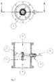
- FIG. 1 shows an overview of the gas treatment system object of the invention
- FIG. 2 shows a section of a detail of the vapor separation module of the invention
- FIG. 3 shows a section view of a detail of the photodissociation cell module of the invention
- FIG. 4 shows a front view of the emitter anode related to the photodissociation cell module
- FIG. 5 is a side view of the intake module of the invention.
- FIG. 6 is a block chart of the pulse generator of the invention.
- the invention generally provides an exhaust gas purification device 100 of an internal combustion engine, comprising:
- a vapor separation module comprising
- the invention generally provides a method for purifying the exhaust gas released by an internal combustion engine provided with a device according to the preceding claims, such a method comprising the following steps:
- FIG. 1 An exhaust gas treatment system according to the present invention is shown in FIG. 1 .
- Said system comprises a module 1 for separating the vapor from the exhaust gas, a module 2 for aspirating the gas treated in module 1 and for introducing said gas into module 3 where the gas molecular dissociation occurs.
- the vapor separating module 1 comprises a cylindrical container having a vertical axis and arranged in the lower part of the treatment system, as shown in FIG. 1 .
- the vapor separation module 1 described in greater detail with reference to FIG. 2 , is provided with an exhaust gas inlet 4 located at the base of the cylindrical container. Inlet 4 is connected to the engine outlet gas delivery.
- Module 1 comprises an outlet 9 for the treated gases located in the upper part of the cylindrical container; through this outlet 9 , module 1 is connected to the next intake module 2 ( FIG. 5 ) by means of a coupling joint, preferably of the ISO-KF or equivalent type, at section 16 .
- Module 2 is, in turn, connected to the next module 3 , photodissociation cell, ( FIG. 3 ) by means of a coupling joint, preferably of the ISO-KF or equivalent type, at sections 19 and 15 .
- the exhaust gas containing carbon dioxide and water in vapor state flows from the exhaust of the internal combustion engine through the inlet pipe 4 into the separation module 1 where it passes through a cooling fluid 8 .
- the aqueous vapor undergoes a condensation process in the cylindrical container. Once entered, the gases cross the volume of liquid 8 present in the lower part of the cylindrical container by bubbling, thus releasing any particles present in suspension in the gas.
- the gas then sequentially crosses a series of partitions 5 , 6 , and 7 to reach the upper part of the cylindrical container.
- the cooled gas by coming into contact with the surface of the partitions 5 , 6 , 7 , surrenders the drops of humidity present therein due to interference, which drops are deposited on the metal surface of the partitions themselves.
- the gas now mostly consisting of carbon dioxide without aqueous vapor or particles, thus reaches the top of the cylindrical container, exiting definitively from module 1 at section 9 .
- the vapor separation treatment operated within module 1 ensures that the exhaust gas released from section 9 is under perfect electric insulating conditions.
- the treated gas thus enters into the intake module 2 ( FIG. 5 ) at section 16 .
- a module comprises a radial centrifuge aspirator, and in particular comprises a self-ventilated electric motor 17 , coupled to a blade impeller, and a cochlea 18 .
- Such an intake module 2 is used to compensate for the loss of load introduced by the vapor separating module 1 in order to keep the gas flow uniform at the photodissociation cell 3 inlet.
- the gas thus enters into the photodissociation cell 3 at section 10 ( FIG. 3 ).
- a unidirectional pulsating electric field is applied in this module 3 between anode 11 and cathode, the cylindrical walls of cell 3 being the cathode.
- the carbon dioxide is eliminated by means of a molecular dissociation process, thus recovering the oxygen lost with the combustion.
- the gas to be treated being free from liquid or solid suspensions, is subjected to bombarding with ultraviolet rays, thus simultaneously eliminating the carbon.
- the gas to be treated is introduced into cell 6 through inlet 10 ( FIG. 3 ), where it is subjected to the flow of ultraviolet rays for emerging after the treatment through the second opening 15 .
- the electric field is applied by connecting the phase of the pulse generator to the power supply wire 12 , which, by crossing insulator 14 , is in turn electrically connected to the anode 11 formed by a plurality of filiform antennas ( FIG. 4 ).
- the neutral of the pulse generator, or cathode, is integrally connected to the metal structure of the photodissociation cell.
- the unidirectional pulsating electric field causes the electrons to oscillate on the tips of anode 11 .
- the ultraviolet radiation is produced by the oscillations of the clouds of electrons which are formed on the tips of the filiform antennas, which form the anode 11 of the cell, in the presence of a uniform pulsated electric field of high intensity but of a value lower than that required to form a discharge in the gas.
- the ultraviolet radiation causes the dissociation of the carbon dioxide molecule into two negative oxygen ions and into one positive carbon ion.
- the carbon ion attracted by the walls of cell 6 will form a weak current, thus closing the electric circuit.
- the oxygen ions are pushed out of cell 6 where they Will form oxygen molecules.
- the treated gas exits definitely from module 3 at section 15 .
- FIG. 6 shows a block chart of the pulse generator which supplies the photodissociation cell.
- the pulse generator consists of seven distinct modules:
- Insulated AC-DC power supply by means of a transformer
- output voltage adjustable by means of a trimmer range ⁇ 10-16 Vdc
- Output power available ⁇ 4.5 W.
- Power switch driven by the signal generated by the Multivibrator.
- the power signal is supplied directly by the AC-DC power supply out.
- the AC-DC Converter transforms the non-stabilized 220V-50 Hz mains alternating voltage, which is sent to the stabilized voltage regulator (DC-DC Converter) and to the drain of the power MOSFET in common source configuration.
- the direct voltage output of the DC-DC Converter stabilized at 8 V is used to supply the Multivibrator (integrated NE 555), which generates a pulse train with frequency of 15.8 kHz which drives the power MOSFET gate.
- the Multivibrator integrated NE 555
- the power MOSFET outputs a pulse train with 0-12 VDC voltage levels with the same frequency equal to 15.8 kHz.
- the power MOSFET is connected to the primary of the Flyback Transformer (EAT) which supplies the high voltage level of the 8 kV pulse train to its secondary. Therefore, downstream of the Flyback Transformer (EAT), the voltage level is a 0-8 kV pulse train with frequency of 15.8 kHz.
- the output of the secondary Flyback Transformer is connected to the Voltage Multiplier input which triplicates the high voltage level of the pulse train taking it to 0-24 kV with the same frequency of 15.8 kHz.
- the output of the Voltage Multiplier at 0-24 kV 15.8 kHz is supplied to the cell anode.
- an analog ammeter is inserted in series between the 12V output of the AC DC Converter and the power MOSFET drain.
- a LED is inserted with the resistance thereof in series having one of the two ends connected to a conductor wire wound about the ferrite of the Flyback Transformer (EAT).
- the LED is supplied by the current generated by electromagnetic induction by the current passing and crossing the secondary of the Flyback Transformer (EAT), thus providing visual feedback to the current directed to the anode of the cell.
- the circuit diagram above also allows the linear adjustment of the high value of the pulse power supply voltage of the cell anode.
- the adjustment is allowed by acting on the AC DC Converter to vary the output voltage in a range from 10V to 16V DC.
- the device according to the invention allows to purify the exhaust gases of the internal combustion engine and to convert them into oxygen, which may be used again for combustion or can be re-introduced into the atmosphere.
- the device is actually usable in all thermal system types based on the combustion of fossil fuels.
- Important advantages of the system include not forming residues, such as carbon emission, and re-introducing the oxygen consumed during the combustion process and recovered by means of the photodissociation process into the atmosphere or reusing it.
Landscapes
- Chemical & Material Sciences (AREA)
- Engineering & Computer Science (AREA)
- Chemical Kinetics & Catalysis (AREA)
- General Chemical & Material Sciences (AREA)
- Oil, Petroleum & Natural Gas (AREA)
- Analytical Chemistry (AREA)
- Health & Medical Sciences (AREA)
- Biomedical Technology (AREA)
- Environmental & Geological Engineering (AREA)
- Combustion & Propulsion (AREA)
- Physics & Mathematics (AREA)
- Thermal Sciences (AREA)
- Toxicology (AREA)
- Treating Waste Gases (AREA)
- Exhaust Gas After Treatment (AREA)
- Separation Of Particles Using Liquids (AREA)
- Drying Of Gases (AREA)
- Vaporization, Distillation, Condensation, Sublimation, And Cold Traps (AREA)
- Processes For Solid Components From Exhaust (AREA)
Abstract
Description
-
- Thermal molecular dissociation, which is a high energy intensity process
- Chemical molecular dissociation, with implications related to disposal
- Gas discharge dissociation, with very low energy efficiencies
- Hydrolysis reactions requiring frequent replacement of the concerned waste reactants
- Mechanical, electrostatic and UV filters having poor efficiency on large aeriform masses.
b) an intake module, comprising a radial blade fan with vertical rotation axis for aspirating the exhaust gas through an inlet connected to said outlet of the cylindrical container and provided with an outlet for expelling the aspirated gases;
c) a module consisting of a photodissociation cell, in which the exhaust gas, dried and free from solid suspensions, is subjected to a photodissociation process, by means of which the carbon dioxide contained in said gas is split into its components, said photodissociation cell being provided with an opening for introducing the exhaust gas connected to the outlet of said intake module and with an opening for releasing the gas resulting from the photodissociation.
-
- a
cylindrical container 1 with vertical rotation axis and having a lower part and an upper part, said separation module having an inlet 4 for introducing exhaust gas located in the lower part and provided with a fluid-tight valve, - a cover which closes the upper end of said
cylindrical container 1, an outlet 9 being located on said cover for the exhaust gas treated in said vapor separation module; - separation means for retaining water vapor and solid particles from the exhaust gas,
whereby the separation module is configured to remove water vapor and solid particles from said exhaust gas, thus obtaining dried gas which is dried and free from solid suspensions,
b) anintake module 2 comprising
aninlet 16 connected to the outlet 9 of the separation module,
a radial blade fan with vertical rotation axis,
anoutlet 19,
theintake module 2 being configured to aspirate the dried gas throughinlet 16 and to expel it throughoutlet 19;
c) amodule 3 consisting of a photodissociation cell,
said photodissociation cell being provided with anopening 10 connected to theoutlet 19 of saidintake module 2 for introducing the dried gas and an opening 15 for releasing the gas resulting from the photodissociation,
the photodissociation cell comprising
afirst electrode 11 which acts as an anode, formed by a plurality of filiform antennas,
a second electrode, consisting of the wall of the photodissociation cell,
a pulse generator connected to the first electrode and to the second electrode,
the photodissociation cell being configured to generate ultraviolet rays by applying a unidirectional pulsating electric field by means of the pulse generator to the first electrode and the second electrode,
whereby the dried gas is subjected in thedissociation module 3 to a photodissociation process by means of which the carbon dioxide contained in said dried gas is broken down into its components.
- a
Claims (7)
Applications Claiming Priority (3)
| Application Number | Priority Date | Filing Date | Title |
|---|---|---|---|
| IT102015000064740 | 2015-10-23 | ||
| ITUB2015A005040A ITUB20155040A1 (en) | 2015-10-23 | 2015-10-23 | Device for purifying exhaust gases from endothermic engines |
| PCT/IB2016/056379 WO2017068557A1 (en) | 2015-10-23 | 2016-10-24 | Device and method for purifying exhaust gas from endothermic engines |
Publications (2)
| Publication Number | Publication Date |
|---|---|
| US20180311615A1 US20180311615A1 (en) | 2018-11-01 |
| US10758865B2 true US10758865B2 (en) | 2020-09-01 |
Family
ID=55359612
Family Applications (1)
| Application Number | Title | Priority Date | Filing Date |
|---|---|---|---|
| US15/770,377 Expired - Fee Related US10758865B2 (en) | 2015-10-23 | 2016-10-24 | Device and method for purifying exhaust gas from endothermic engines |
Country Status (6)
| Country | Link |
|---|---|
| US (1) | US10758865B2 (en) |
| EP (1) | EP3365092B1 (en) |
| JP (1) | JP6771550B2 (en) |
| CN (1) | CN108697974B (en) |
| IT (1) | ITUB20155040A1 (en) |
| WO (1) | WO2017068557A1 (en) |
Families Citing this family (1)
| Publication number | Priority date | Publication date | Assignee | Title |
|---|---|---|---|---|
| CN112007431A (en) * | 2019-05-31 | 2020-12-01 | 江苏国威化工有限公司 | Chlorinated paraffin tail gas pretreatment method and treatment equipment thereof |
Citations (11)
| Publication number | Priority date | Publication date | Assignee | Title |
|---|---|---|---|---|
| US3236045A (en) * | 1963-03-01 | 1966-02-22 | Michel C Berger | Combustion gas discharge system |
| US3304711A (en) * | 1965-09-21 | 1967-02-21 | Ernest A Eastman | Exhaust converter |
| FR2495492A1 (en) | 1980-12-04 | 1982-06-11 | Gohin Poulenc Cie | Drying and purificn. of compressed gas, esp. air - which is bubbled through cold water so moisture content of gas is reduced while impurities are washed out of gas |
| US5714665A (en) | 1995-02-23 | 1998-02-03 | The Tokyo Electric Power Co., Inc. | Method and apparatus for the decomposition and re-use-as-resource treatment of ozone layer-depleting substances by application of UV light |
| US6168689B1 (en) * | 1995-12-28 | 2001-01-02 | Seondo Electric Co., Ltd. | Method and apparatus for cleaning exhaust gas discharged from internal or external combustion engine by using high voltage electric field |
| WO2007107544A2 (en) | 2006-03-21 | 2007-09-27 | Zete S.R.L. | Method for dissociating compound molecules present in aeriforms, device for implementing the method, and some of its uses |
| US20070231233A1 (en) * | 2006-03-31 | 2007-10-04 | Ranendra Bose | Methane gas recovery and usage system for coalmines, municipal land fills and oil refinery distillation tower vent stacks |
| US20120093691A1 (en) * | 2009-03-24 | 2012-04-19 | Tri-Air Developments Limited | Improved air decontamination device and method |
| DE202014002419U1 (en) | 2014-03-18 | 2014-04-15 | Georg Vogel | Device for reducing the CO2 content in an exhaust gas emitted by an internal combustion engine |
| EP2862619A1 (en) | 2013-10-21 | 2015-04-22 | IMIS Spolka z ograniczona | A method of disociation of exhaust gases, in particular of gases containing carbon dioxide (CO2) and a reactor chamber |
| US20150360177A1 (en) * | 2013-02-01 | 2015-12-17 | Hino Motors, Ltd. | Exhaust gas purification system and ozone generator |
Family Cites Families (6)
| Publication number | Priority date | Publication date | Assignee | Title |
|---|---|---|---|---|
| JP2000084355A (en) * | 1998-09-10 | 2000-03-28 | Tomoji Tanaka | Purification of combustion exhaust gas from automobile and others |
| JP2001276546A (en) * | 2000-03-29 | 2001-10-09 | Kiyomitsu Ono | Dust removing device |
| JP2003117336A (en) * | 2001-10-11 | 2003-04-22 | Ishihara Rinzai Kk | Liquid filtrate and apparatus for cleaning waste gas using the same |
| CN1270810C (en) * | 2003-03-21 | 2006-08-23 | 诸瑞青 | Smoke exhaust pollution treatment equipment |
| CN101963082B (en) * | 2010-09-02 | 2013-06-05 | 青岛文创科技有限公司 | Vehicle exhaust purification and recovery device |
| JP2015055167A (en) * | 2013-09-11 | 2015-03-23 | いすゞ自動車株式会社 | Exhaust emission control device |
-
2015
- 2015-10-23 IT ITUB2015A005040A patent/ITUB20155040A1/en unknown
-
2016
- 2016-10-24 EP EP16812829.6A patent/EP3365092B1/en active Active
- 2016-10-24 US US15/770,377 patent/US10758865B2/en not_active Expired - Fee Related
- 2016-10-24 JP JP2018517749A patent/JP6771550B2/en active Active
- 2016-10-24 CN CN201680061664.6A patent/CN108697974B/en active Active
- 2016-10-24 WO PCT/IB2016/056379 patent/WO2017068557A1/en not_active Ceased
Patent Citations (11)
| Publication number | Priority date | Publication date | Assignee | Title |
|---|---|---|---|---|
| US3236045A (en) * | 1963-03-01 | 1966-02-22 | Michel C Berger | Combustion gas discharge system |
| US3304711A (en) * | 1965-09-21 | 1967-02-21 | Ernest A Eastman | Exhaust converter |
| FR2495492A1 (en) | 1980-12-04 | 1982-06-11 | Gohin Poulenc Cie | Drying and purificn. of compressed gas, esp. air - which is bubbled through cold water so moisture content of gas is reduced while impurities are washed out of gas |
| US5714665A (en) | 1995-02-23 | 1998-02-03 | The Tokyo Electric Power Co., Inc. | Method and apparatus for the decomposition and re-use-as-resource treatment of ozone layer-depleting substances by application of UV light |
| US6168689B1 (en) * | 1995-12-28 | 2001-01-02 | Seondo Electric Co., Ltd. | Method and apparatus for cleaning exhaust gas discharged from internal or external combustion engine by using high voltage electric field |
| WO2007107544A2 (en) | 2006-03-21 | 2007-09-27 | Zete S.R.L. | Method for dissociating compound molecules present in aeriforms, device for implementing the method, and some of its uses |
| US20070231233A1 (en) * | 2006-03-31 | 2007-10-04 | Ranendra Bose | Methane gas recovery and usage system for coalmines, municipal land fills and oil refinery distillation tower vent stacks |
| US20120093691A1 (en) * | 2009-03-24 | 2012-04-19 | Tri-Air Developments Limited | Improved air decontamination device and method |
| US20150360177A1 (en) * | 2013-02-01 | 2015-12-17 | Hino Motors, Ltd. | Exhaust gas purification system and ozone generator |
| EP2862619A1 (en) | 2013-10-21 | 2015-04-22 | IMIS Spolka z ograniczona | A method of disociation of exhaust gases, in particular of gases containing carbon dioxide (CO2) and a reactor chamber |
| DE202014002419U1 (en) | 2014-03-18 | 2014-04-15 | Georg Vogel | Device for reducing the CO2 content in an exhaust gas emitted by an internal combustion engine |
Non-Patent Citations (1)
| Title |
|---|
| International Search Report for PCT/IB2016/056379 dated Feb. 14, 2017. |
Also Published As
| Publication number | Publication date |
|---|---|
| JP2018532939A (en) | 2018-11-08 |
| CN108697974A (en) | 2018-10-23 |
| US20180311615A1 (en) | 2018-11-01 |
| ITUB20155040A1 (en) | 2017-04-23 |
| JP6771550B2 (en) | 2020-10-21 |
| WO2017068557A1 (en) | 2017-04-27 |
| CN108697974B (en) | 2021-02-26 |
| EP3365092A1 (en) | 2018-08-29 |
| EP3365092B1 (en) | 2019-12-11 |
Similar Documents
| Publication | Publication Date | Title |
|---|---|---|
| KR101430647B1 (en) | air cleaning streetlight | |
| CN105396440B (en) | The device and method of thermoelectricity corona catalytic oxidation treatment industrial waste gas VOCs | |
| US6878349B2 (en) | Pollution control device | |
| CN104096460A (en) | Plasma waste gas treatment device | |
| KR20150018714A (en) | Water treatment apparatus using plasma-membrane and method using the same | |
| US10758865B2 (en) | Device and method for purifying exhaust gas from endothermic engines | |
| CN106823791A (en) | A kind of plasma cooperative photocatalysis purifier and purification method | |
| EP0839069B1 (en) | A method and apparatus for purifying a gaseous mixture including molecules and/or cells of toxic or polluting substances | |
| CN103362602B (en) | Automobile exhaust gas purifying installation | |
| CN208161265U (en) | A kind of device for eliminating white smoke for flue gas | |
| CN203108410U (en) | Processing device and processing system for nonuniform field intensity plasma waste gas | |
| CN101920038A (en) | Submarine low temperature plasma air sterilization purifier | |
| CN204121951U (en) | A kind of plasma waste gas treating device | |
| CN216703891U (en) | Plasma deodorization control device | |
| CN201997244U (en) | High-energy low-temperature plasma purifying device | |
| CN105797546A (en) | Purification device and purification method for industrial waste gas | |
| CN204543940U (en) | Industrial waste-gas purifier | |
| CN104984647A (en) | Organic waste gas treatment method and special apparatus thereof | |
| CN210097248U (en) | Waste gas treatment device for concrete mixing plant | |
| CN207287136U (en) | A kind of plasma cooperative photocatalysis purifier | |
| CN114748991B (en) | Low-temperature plasma deodorization system based on gas electrolysis ionization technology | |
| CN117647948B (en) | Control circuit, gas treatment device and control method | |
| CN206500023U (en) | A kind of sewage treatment plant's exhaust treatment system | |
| CN212777545U (en) | Kitchen oil fume treatment device | |
| WO2007107544A2 (en) | Method for dissociating compound molecules present in aeriforms, device for implementing the method, and some of its uses |
Legal Events
| Date | Code | Title | Description |
|---|---|---|---|
| FEPP | Fee payment procedure |
Free format text: ENTITY STATUS SET TO UNDISCOUNTED (ORIGINAL EVENT CODE: BIG.); ENTITY STATUS OF PATENT OWNER: LARGE ENTITY |
|
| STPP | Information on status: patent application and granting procedure in general |
Free format text: DOCKETED NEW CASE - READY FOR EXAMINATION |
|
| STPP | Information on status: patent application and granting procedure in general |
Free format text: NON FINAL ACTION MAILED |
|
| AS | Assignment |
Owner name: I.R.C.A. S.P.A INDUSTRIA RESISTENZE CORAZZATE E AF Free format text: ASSIGNMENT OF ASSIGNORS INTEREST;ASSIGNORS:ZOPPAS, FREDERICO;SAVI, BRUNO;SIGNING DATES FROM 20190801 TO 20191024;REEL/FRAME:051172/0662 Owner name: I.R.C.A. S.P.A INDUSTRIA RESISTENZE CORAZZATE E AFFINI, ITALY Free format text: ASSIGNMENT OF ASSIGNORS INTEREST;ASSIGNORS:ZOPPAS, FREDERICO;SAVI, BRUNO;SIGNING DATES FROM 20190801 TO 20191024;REEL/FRAME:051172/0662 |
|
| STPP | Information on status: patent application and granting procedure in general |
Free format text: RESPONSE TO NON-FINAL OFFICE ACTION ENTERED AND FORWARDED TO EXAMINER |
|
| ZAAA | Notice of allowance and fees due |
Free format text: ORIGINAL CODE: NOA |
|
| ZAAB | Notice of allowance mailed |
Free format text: ORIGINAL CODE: MN/=. |
|
| STCF | Information on status: patent grant |
Free format text: PATENTED CASE |
|
| FEPP | Fee payment procedure |
Free format text: MAINTENANCE FEE REMINDER MAILED (ORIGINAL EVENT CODE: REM.); ENTITY STATUS OF PATENT OWNER: LARGE ENTITY |
|
| LAPS | Lapse for failure to pay maintenance fees |
Free format text: PATENT EXPIRED FOR FAILURE TO PAY MAINTENANCE FEES (ORIGINAL EVENT CODE: EXP.); ENTITY STATUS OF PATENT OWNER: LARGE ENTITY |
|
| STCH | Information on status: patent discontinuation |
Free format text: PATENT EXPIRED DUE TO NONPAYMENT OF MAINTENANCE FEES UNDER 37 CFR 1.362 |
|
| FP | Lapsed due to failure to pay maintenance fee |
Effective date: 20240901 |