US1075868A - Danger-signal for railway-bridges. - Google Patents
Danger-signal for railway-bridges. Download PDFInfo
- Publication number
- US1075868A US1075868A US71428212A US1912714282A US1075868A US 1075868 A US1075868 A US 1075868A US 71428212 A US71428212 A US 71428212A US 1912714282 A US1912714282 A US 1912714282A US 1075868 A US1075868 A US 1075868A
- Authority
- US
- United States
- Prior art keywords
- signal
- arm
- danger
- bridge
- cable
- Prior art date
- Legal status (The legal status is an assumption and is not a legal conclusion. Google has not performed a legal analysis and makes no representation as to the accuracy of the status listed.)
- Expired - Lifetime
Links
- 230000007246 mechanism Effects 0.000 description 5
- 230000011664 signaling Effects 0.000 description 5
- 230000007727 signaling mechanism Effects 0.000 description 5
- XLYOFNOQVPJJNP-UHFFFAOYSA-N water Substances O XLYOFNOQVPJJNP-UHFFFAOYSA-N 0.000 description 4
- 230000000694 effects Effects 0.000 description 2
- 244000025254 Cannabis sativa Species 0.000 description 1
- 235000012766 Cannabis sativa ssp. sativa var. sativa Nutrition 0.000 description 1
- 235000012765 Cannabis sativa ssp. sativa var. spontanea Nutrition 0.000 description 1
- 102100040954 Ephrin-A1 Human genes 0.000 description 1
- 101000965523 Homo sapiens Ephrin-A1 Proteins 0.000 description 1
- 235000009120 camo Nutrition 0.000 description 1
- 235000005607 chanvre indien Nutrition 0.000 description 1
- 238000010276 construction Methods 0.000 description 1
- 239000011487 hemp Substances 0.000 description 1
- 239000000543 intermediate Substances 0.000 description 1
- 239000000463 material Substances 0.000 description 1
- 229920000136 polysorbate Polymers 0.000 description 1
- 230000000630 rising effect Effects 0.000 description 1
Images

Classifications
-
- B—PERFORMING OPERATIONS; TRANSPORTING
- B61—RAILWAYS
- B61L—GUIDING RAILWAY TRAFFIC; ENSURING THE SAFETY OF RAILWAY TRAFFIC
- B61L23/00—Control, warning or like safety means along the route or between vehicles or trains
- B61L23/04—Control, warning or like safety means along the route or between vehicles or trains for monitoring the mechanical state of the route
- B61L23/041—Obstacle detection
Definitions
- Patented (lot. 14, 1913.
- This invention relates to danger signals for railway bridges.
- the object of the invention resides in the provision of a danger signal to be placed near the approach of railway bridges and which will act automatically in the event of the bridge being burned or washed away or flooded so as to warn approaching trains of danger and thereby enable such trains to stop in time to avoid serious accident.
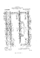
- Figure 1 is a plan view of a railway track including a bridge section and having the improved danger signal associated therewith, said signal being in its normal or safety position
- Fig. 2 a section on the line 2-2 of Fig. 1, Fig. 3, a side elevation of what is shown in Fig. 1, Fig. 4, a section on the line 4r4 of Fig. 1 showing the means for releasing the signal to danger position when the water beneath the bridge is abnormally high said means being in the position it would occupy before effecting the release of the signal
- Fig. 5 a view similar to Fig.
- Fig. 6 a section on the line 66 of Fig. 1, Fig. 7, a view similar to Fig. 6 showing the adjacent signal released to danger position, and Fig. 8, a detail perspective view of one of the signals disclosing the holoing mechanism.
- a railroad track which includes terminal land sections A and B and an inter mediate bridge section C. Disposed adjacent the land section A. of the track is a signal pole 10 which has pivoted to the upper end thereof a signal arm 11. One end of this arm 11 is provided with a weight 12 which constantly tends to move the arm 11 to danger position as shown in Fig. 7, the movement of the arm 11 under the influence of the weight 12 being limited by means of a stop 13 on the pole 10. Pivot-ally con nected to the arm 11 between the weight 12 and the pivot of said arm 11 is one end of an arm 14. This arm 14 extends substantially contiguous with the pole l0 and is directed through a guide member 15 carried oy the pole 10.
- a shaft 16 Journaled transversely of the pole 10 adjacent the lower end of the arm 14 is a shaft 16 the terminals of which are provided respectively with laterally directed arms 17 and 18.
- the arm 18 is provided at its free end with a loop 19 for a purpose that will presently appear, while the arm 17 has adjustably mounted th reon a weight 20.
- F ixed on the shaft 16 between the arms 17 and 18 is a wing or plate 21 which when the shaft 16 is rotated in one direction is adapted to be positioned so as to support the lower end of the arm 1 1- and thereby hold the signal arm 11 in safety position against the influence of the weight 12.
- a similar pole and signalin mechanism to that just described is positioned adjacent the track section B and because of the fact that the various parts of the signaling mechanism adjacent the track section B are identical with the parts of the signaling mechanism adjacent the track section A a detail description thereof will be omitted and the same reference characters utilized in indicating the parts as indicate corresponding parts in the signaling mechanism adjacent the track section A.
- a plurality of pulleys 22 over which is trained a cable 23.
- the terminals of this cable 23 are connected respectively to the loops 19 on the free ends of the arms 18 and is drawn sufficiently taut to move the wings or plates 21 carried by each shaft 16 to a position for supporting the arms 14 of respective signals so that the signal arms 11 will be normally held in safety position against the influence of the weights 12.
- the arm 26 is adapted to be moved so as to sever the cable 28 through the influence of water rising beneath the bridge until it engages the buoyant blocks 28. When this engagement takes place the current will act upon the blocks 28 in a manner to effect the desired movement of the arm 26 as will be obvious.
- the cable 23 may be constructed of various 1naterials as a whole or may be composed of? different materials, it being only essential that the portion of the cable which spans the bridge section C be adapted to be severed under the conditions named. That portion: of the cable 23 which spans the bridge sec-; tion C is preferably constructed of hemp* rope suitably treated to prevent rotting.
- the sigi nals will be located a suflicient distance from? each end of the bridge to enable a train toj; stop in ample time in the event of dangeri and that the signals will be provided with; light as is customary so that they may be observed at night.
- the cable may be cov-i ered in order to protect same and the number 1 of pulleys increased in proportion to thel length of the cable.
- said cable being adapted to be severed under predetermined conditions whereby the shafts are free to rotate under the influence of the weights on respective lateral arms thereof to release the signaling arms for movement to danger position.
Landscapes
- Engineering & Computer Science (AREA)
- Mechanical Engineering (AREA)
- Train Traffic Observation, Control, And Security (AREA)
Description
J. E. SJOMAN. [DANGER SIGNAL FOR RAILWAY BRIDGES.
APPLICATION FILED Aims. 1912.
Patented 0013. 14, 1913.
2 sums-SHEET 1.
COLUMBI A PLANOORAFH 60.. WASHINGTON, D. c.
J. E. SJOMAN. DANGER SIGNAL ron RAILWAY BRIDGES.
{APPLICATION FILED Ave. 9, 1912. 1,975,868. Patented Oct. 14, 1913.
w 2 sums-sum 2.
Swvmtw COLUMBIA PLANOGRAPM 60.,WASHINGTON. n. c.
JOHN E. SJ'GMAN, OF QSAGE CITY, KANSAS.
DANGER-SIGNAL FOR RAILWAY-BRIDGES.
Specification of Letters Patent.
Patented (lot. 14, 1913.
Application filed August 9, 1912. Serial No. 714,282.
To all whom it may concern:
Be it known that 1, JOHN E. SJOMAN, a citizen of the United States, residing at Osage City, in the county of Osage, State of Kansas, have invented certain new and useful Improvements in Danger-Signals for Railway-Bridges; and I do hereby declare the following to be a full, clear, and exact description of the invention, such as will enable others skilled in the art to which it appertains to make and use the same.
This invention relates to danger signals for railway bridges.
The object of the invention resides in the provision of a danger signal to be placed near the approach of railway bridges and which will act automatically in the event of the bridge being burned or washed away or flooded so as to warn approaching trains of danger and thereby enable such trains to stop in time to avoid serious accident.
With the above and other objects in view, the invention consists in the details of construction and in the arrangement and combination of parts to be hereinafter more fully described and particularly pointed out in the appended claims.
In describing the invention in detail, reference will be had to the accompanying drawings wherein like characters of reference denote corresponding parts in the several views, and in which- Figure 1 is a plan view of a railway track including a bridge section and having the improved danger signal associated therewith, said signal being in its normal or safety position, Fig. 2, a section on the line 2-2 of Fig. 1, Fig. 3, a side elevation of what is shown in Fig. 1, Fig. 4, a section on the line 4r4 of Fig. 1 showing the means for releasing the signal to danger position when the water beneath the bridge is abnormally high said means being in the position it would occupy before effecting the release of the signal, Fig. 5, a view similar to Fig. 1- showing the means for releasing the signal to danger position in the position it would occupy when the signal has been released thereby, Fig. 6, a section on the line 66 of Fig. 1, Fig. 7, a view similar to Fig. 6 showing the adjacent signal released to danger position, and Fig. 8, a detail perspective view of one of the signals disclosing the holoing mechanism.
Referring to the drawings there is disclosed a railroad track which includes terminal land sections A and B and an inter mediate bridge section C. Disposed adjacent the land section A. of the track is a signal pole 10 which has pivoted to the upper end thereof a signal arm 11. One end of this arm 11 is provided with a weight 12 which constantly tends to move the arm 11 to danger position as shown in Fig. 7, the movement of the arm 11 under the influence of the weight 12 being limited by means of a stop 13 on the pole 10. Pivot-ally con nected to the arm 11 between the weight 12 and the pivot of said arm 11 is one end of an arm 14. This arm 14 extends substantially contiguous with the pole l0 and is directed through a guide member 15 carried oy the pole 10. Journaled transversely of the pole 10 adjacent the lower end of the arm 14 is a shaft 16 the terminals of which are provided respectively with laterally directed arms 17 and 18. The arm 18 is provided at its free end with a loop 19 for a purpose that will presently appear, while the arm 17 has adjustably mounted th reon a weight 20. F ixed on the shaft 16 between the arms 17 and 18 is a wing or plate 21 which when the shaft 16 is rotated in one direction is adapted to be positioned so as to support the lower end of the arm 1 1- and thereby hold the signal arm 11 in safety position against the influence of the weight 12. A similar pole and signalin mechanism to that just described is positioned adjacent the track section B and because of the fact that the various parts of the signaling mechanism adjacent the track section B are identical with the parts of the signaling mechanism adjacent the track section A a detail description thereof will be omitted and the same reference characters utilized in indicating the parts as indicate corresponding parts in the signaling mechanism adjacent the track section A.
Mounted upon the bridge section C is a plurality of pulleys 22 over which is trained a cable 23. The terminals of this cable 23 are connected respectively to the loops 19 on the free ends of the arms 18 and is drawn sufficiently taut to move the wings or plates 21 carried by each shaft 16 to a position for supporting the arms 14 of respective signals so that the signal arms 11 will be normally held in safety position against the influence of the weights 12. With the signaling mechanism thus arranged it will be apparent that in case of the bridge section C being burned or washed out the cable 23 will be severed and the shafts 16 rotated under the influence of the weights 20 so as to release the signal arms 11 for movement to clan-- ger position under the influence of the weights 12.
Mounted upon one of the ties of the bridge section G is a pair of spaced plates 24: and
25 and between these plates is pivotally secured one end of an arm 26. The upper end; of this arm is beveled and provided with a? knife edge 27 while the lower end thereofi has secured thereto blocks of buoyant ma-} terial 28. In the normal position of the arm 26 the major port-ion of the knife edge 27 5 thereof is disposed outwardly of the plates 24 and 25 and the cable 23 passes between? this knife edge 27 and said plates 24 and 25? so that when the arm 26 is swung in one; direction the knife edge 27 will move be-' tween the plates 24: and 25 and sever the ca Me, 23 so as to release the signaling mechanisms at each end of the bridge todanger position. The arm 26 is adapted to be moved so as to sever the cable 28 through the influence of water rising beneath the bridge until it engages the buoyant blocks 28. When this engagement takes place the current will act upon the blocks 28 in a manner to effect the desired movement of the arm 26 as will be obvious.
It will of course be understood that the cable 23 may be constructed of various 1naterials as a whole or may be composed of? different materials, it being only essential that the portion of the cable which spans the bridge section C be adapted to be severed under the conditions named. That portion: of the cable 23 which spans the bridge sec-; tion C is preferably constructed of hemp* rope suitably treated to prevent rotting.
It will be further understood that the sigi nals will be located a suflicient distance from? each end of the bridge to enable a train toj; stop in ample time in the event of dangeri and that the signals will be provided with; light as is customary so that they may be observed at night. The cable may be cov-i ered in order to protect same and the number 1 of pulleys increased in proportion to thel length of the cable.
What is claimed is: 1
1. The combination of a bridge, an llp-i right disposed adjacent each end of thei bridge, a signal arm pivoted on each upright, a weight on each arm constantly tending to move same to danger position, a shaft journaled on each upright, lateral arms on each end of said shafts, a weight adjustably mounted on one of said lateral arms of each shaft and constantly tending to rotate said shafts in one direction, a plate fixed on each shaft between the lateral arms, a rod for each signaling arm having one end pivotally connected to each signaling arm and adapted to engage the plate on the adjacent shaft to hold the signaling arm in safe position against the influence of the weight carried thereby, and a cable engaging the bridge and connectlng the other lateral arms of said shafts to hold the latter in position to support the signaling arms in safe position,
said cable being adapted to be severed under predetermined conditions whereby the shafts are free to rotate under the influence of the weights on respective lateral arms thereof to release the signaling arms for movement to danger position.
2. The combination of a bridge, a semaihore signal disposed at each end of the bridge, means constantly tending to move said signals to danger position, a holding mechanism for each signal adapted to hold the latter in safe position against the influence of said means, a pair of spaced members mounted on the bridge, a plate having one end pivo-tally mounted between said mem bers and depending from the bridge, the upper end of said plate being beveled and provided with a knife edge normally disposed without said members, buoyant blocks secured to the lower end of the plate and adapted to effect a swinging of the latter under the influence of a current of water beneath the bridge to move the upper end of the plate between said members and a cable passing between the upper end of said plate and said members and connecting the holding mechanisms whereby the movement of said plate under the influence of a current of water beneath the bridge will sever the cable and release the holding mechanisms.
In testimo-nv whereof, I afliX my signature, in presence of two witnesses.
JOHN E. SJOMAN. Witnesses:
ALBERT LEANDER, ERIo FELLMAN.
Copies of this patent may be obtained for five cents each, by addressing the Commissioner of Patents. Washington, 20.0.
Priority Applications (1)
| Application Number | Priority Date | Filing Date | Title |
|---|---|---|---|
| US71428212A US1075868A (en) | 1912-08-09 | 1912-08-09 | Danger-signal for railway-bridges. |
Applications Claiming Priority (1)
| Application Number | Priority Date | Filing Date | Title |
|---|---|---|---|
| US71428212A US1075868A (en) | 1912-08-09 | 1912-08-09 | Danger-signal for railway-bridges. |
Publications (1)
| Publication Number | Publication Date |
|---|---|
| US1075868A true US1075868A (en) | 1913-10-14 |
Family
ID=3144099
Family Applications (1)
| Application Number | Title | Priority Date | Filing Date |
|---|---|---|---|
| US71428212A Expired - Lifetime US1075868A (en) | 1912-08-09 | 1912-08-09 | Danger-signal for railway-bridges. |
Country Status (1)
| Country | Link |
|---|---|
| US (1) | US1075868A (en) |
-
1912
- 1912-08-09 US US71428212A patent/US1075868A/en not_active Expired - Lifetime
Similar Documents
| Publication | Publication Date | Title |
|---|---|---|
| US1075868A (en) | Danger-signal for railway-bridges. | |
| US1047486A (en) | Automatic railroad block system. | |
| US743063A (en) | Automatic danger-signal for railways. | |
| US387747A (en) | Danger-signal for railway-bridges | |
| US1136793A (en) | Railroad safety device. | |
| US374373A (en) | Josiah d | |
| US812572A (en) | Safety system for railways. | |
| US1087030A (en) | Signal-block. | |
| US666027A (en) | Automatic switch. | |
| US1178655A (en) | Self-signaling device for railroads. | |
| US838153A (en) | Railroad-semaphore. | |
| US571191A (en) | Railway-signal | |
| US96428A (en) | Improved railway supply-apparatus | |
| US401764A (en) | Danger-signal for railway-bridges | |
| US1119871A (en) | Switch-signal apparatus. | |
| US1178711A (en) | Bridge-signal for railroads. | |
| US761825A (en) | Railway signaling device. | |
| US499165A (en) | Automatic railway-signal | |
| US1105099A (en) | Signal apparatus. | |
| US275313A (en) | Railroad crossing and station signal | |
| US321920A (en) | Automatic frogless switch | |
| US406417A (en) | Railroad-gate | |
| US829035A (en) | Mail-crane and danger-signal. | |
| US851989A (en) | Fog signaling apparatus for railways and the like. | |
| US199234A (en) | Improvement in railroad-signals |