US10757783B2 - Color temperature controlled and low THD LED lighting devices and systems and methods of driving the same - Google Patents
Color temperature controlled and low THD LED lighting devices and systems and methods of driving the same Download PDFInfo
- Publication number
- US10757783B2 US10757783B2 US16/440,884 US201916440884A US10757783B2 US 10757783 B2 US10757783 B2 US 10757783B2 US 201916440884 A US201916440884 A US 201916440884A US 10757783 B2 US10757783 B2 US 10757783B2
- Authority
- US
- United States
- Prior art keywords
- led
- leds
- circuit
- lighting device
- led lighting
- Prior art date
- Legal status (The legal status is an assumption and is not a legal conclusion. Google has not performed a legal analysis and makes no representation as to the accuracy of the status listed.)
- Active
Links
- 238000000034 method Methods 0.000 title description 18
- 238000005286 illumination Methods 0.000 claims description 9
- 239000000758 substrate Substances 0.000 claims description 9
- 230000004044 response Effects 0.000 claims description 5
- XLYOFNOQVPJJNP-UHFFFAOYSA-N water Substances O XLYOFNOQVPJJNP-UHFFFAOYSA-N 0.000 claims description 5
- 238000004140 cleaning Methods 0.000 claims description 2
- 239000007921 spray Substances 0.000 claims description 2
- OAICVXFJPJFONN-UHFFFAOYSA-N Phosphorus Chemical compound [P] OAICVXFJPJFONN-UHFFFAOYSA-N 0.000 description 18
- 230000005284 excitation Effects 0.000 description 17
- 238000011965 cell line development Methods 0.000 description 10
- 239000003086 colorant Substances 0.000 description 10
- 239000011248 coating agent Substances 0.000 description 9
- 238000000576 coating method Methods 0.000 description 9
- 230000008901 benefit Effects 0.000 description 7
- 230000004907 flux Effects 0.000 description 7
- 229910052736 halogen Inorganic materials 0.000 description 7
- 150000002367 halogens Chemical class 0.000 description 7
- 230000006872 improvement Effects 0.000 description 7
- 239000004065 semiconductor Substances 0.000 description 7
- 230000007423 decrease Effects 0.000 description 5
- 230000000694 effects Effects 0.000 description 5
- 230000009467 reduction Effects 0.000 description 5
- 230000015556 catabolic process Effects 0.000 description 4
- 238000001816 cooling Methods 0.000 description 4
- 238000004519 manufacturing process Methods 0.000 description 4
- 230000008859 change Effects 0.000 description 3
- 238000006243 chemical reaction Methods 0.000 description 3
- 230000003247 decreasing effect Effects 0.000 description 3
- 238000013461 design Methods 0.000 description 3
- 238000010586 diagram Methods 0.000 description 3
- 230000002441 reversible effect Effects 0.000 description 3
- 230000000630 rising effect Effects 0.000 description 3
- 239000007787 solid Substances 0.000 description 3
- 238000001228 spectrum Methods 0.000 description 3
- 241001465754 Metazoa Species 0.000 description 2
- 230000000712 assembly Effects 0.000 description 2
- 238000000429 assembly Methods 0.000 description 2
- 239000000463 material Substances 0.000 description 2
- 238000013021 overheating Methods 0.000 description 2
- 230000002028 premature Effects 0.000 description 2
- 238000010792 warming Methods 0.000 description 2
- 230000009286 beneficial effect Effects 0.000 description 1
- 230000005540 biological transmission Effects 0.000 description 1
- 230000009194 climbing Effects 0.000 description 1
- 238000004891 communication Methods 0.000 description 1
- 238000005520 cutting process Methods 0.000 description 1
- 238000011161 development Methods 0.000 description 1
- 230000005611 electricity Effects 0.000 description 1
- 238000005516 engineering process Methods 0.000 description 1
- 238000009434 installation Methods 0.000 description 1
- WABPQHHGFIMREM-BJUDXGSMSA-N lead-206 Chemical compound [206Pb] WABPQHHGFIMREM-BJUDXGSMSA-N 0.000 description 1
- WABPQHHGFIMREM-OUBTZVSYSA-N lead-208 Chemical compound [208Pb] WABPQHHGFIMREM-OUBTZVSYSA-N 0.000 description 1
- WABPQHHGFIMREM-AKLPVKDBSA-N lead-210 Chemical compound [210Pb] WABPQHHGFIMREM-AKLPVKDBSA-N 0.000 description 1
- 238000010297 mechanical methods and process Methods 0.000 description 1
- 230000007246 mechanism Effects 0.000 description 1
- 238000012986 modification Methods 0.000 description 1
- 230000004048 modification Effects 0.000 description 1
- 230000000737 periodic effect Effects 0.000 description 1
- 238000011160 research Methods 0.000 description 1
- 238000012546 transfer Methods 0.000 description 1
- 230000007704 transition Effects 0.000 description 1
- 239000002699 waste material Substances 0.000 description 1
Images


Classifications
-
- H—ELECTRICITY
- H05—ELECTRIC TECHNIQUES NOT OTHERWISE PROVIDED FOR
- H05B—ELECTRIC HEATING; ELECTRIC LIGHT SOURCES NOT OTHERWISE PROVIDED FOR; CIRCUIT ARRANGEMENTS FOR ELECTRIC LIGHT SOURCES, IN GENERAL
- H05B45/00—Circuit arrangements for operating light-emitting diodes [LED]
- H05B45/40—Details of LED load circuits
- H05B45/42—Antiparallel configurations
-
- H—ELECTRICITY
- H05—ELECTRIC TECHNIQUES NOT OTHERWISE PROVIDED FOR
- H05B—ELECTRIC HEATING; ELECTRIC LIGHT SOURCES NOT OTHERWISE PROVIDED FOR; CIRCUIT ARRANGEMENTS FOR ELECTRIC LIGHT SOURCES, IN GENERAL
- H05B45/00—Circuit arrangements for operating light-emitting diodes [LED]
- H05B45/10—Controlling the intensity of the light
-
- H—ELECTRICITY
- H05—ELECTRIC TECHNIQUES NOT OTHERWISE PROVIDED FOR
- H05B—ELECTRIC HEATING; ELECTRIC LIGHT SOURCES NOT OTHERWISE PROVIDED FOR; CIRCUIT ARRANGEMENTS FOR ELECTRIC LIGHT SOURCES, IN GENERAL
- H05B45/00—Circuit arrangements for operating light-emitting diodes [LED]
- H05B45/20—Controlling the colour of the light
- H05B45/24—Controlling the colour of the light using electrical feedback from LEDs or from LED modules
-
- H—ELECTRICITY
- H05—ELECTRIC TECHNIQUES NOT OTHERWISE PROVIDED FOR
- H05B—ELECTRIC HEATING; ELECTRIC LIGHT SOURCES NOT OTHERWISE PROVIDED FOR; CIRCUIT ARRANGEMENTS FOR ELECTRIC LIGHT SOURCES, IN GENERAL
- H05B45/00—Circuit arrangements for operating light-emitting diodes [LED]
- H05B45/30—Driver circuits
- H05B45/37—Converter circuits
-
- H—ELECTRICITY
- H05—ELECTRIC TECHNIQUES NOT OTHERWISE PROVIDED FOR
- H05B—ELECTRIC HEATING; ELECTRIC LIGHT SOURCES NOT OTHERWISE PROVIDED FOR; CIRCUIT ARRANGEMENTS FOR ELECTRIC LIGHT SOURCES, IN GENERAL
- H05B45/00—Circuit arrangements for operating light-emitting diodes [LED]
- H05B45/30—Driver circuits
- H05B45/395—Linear regulators
- H05B45/397—Current mirror circuits
-
- H—ELECTRICITY
- H05—ELECTRIC TECHNIQUES NOT OTHERWISE PROVIDED FOR
- H05B—ELECTRIC HEATING; ELECTRIC LIGHT SOURCES NOT OTHERWISE PROVIDED FOR; CIRCUIT ARRANGEMENTS FOR ELECTRIC LIGHT SOURCES, IN GENERAL
- H05B45/00—Circuit arrangements for operating light-emitting diodes [LED]
- H05B45/40—Details of LED load circuits
- H05B45/44—Details of LED load circuits with an active control inside an LED matrix
- H05B45/46—Details of LED load circuits with an active control inside an LED matrix having LEDs disposed in parallel lines
-
- H—ELECTRICITY
- H05—ELECTRIC TECHNIQUES NOT OTHERWISE PROVIDED FOR
- H05B—ELECTRIC HEATING; ELECTRIC LIGHT SOURCES NOT OTHERWISE PROVIDED FOR; CIRCUIT ARRANGEMENTS FOR ELECTRIC LIGHT SOURCES, IN GENERAL
- H05B45/00—Circuit arrangements for operating light-emitting diodes [LED]
- H05B45/40—Details of LED load circuits
- H05B45/44—Details of LED load circuits with an active control inside an LED matrix
- H05B45/48—Details of LED load circuits with an active control inside an LED matrix having LEDs organised in strings and incorporating parallel shunting devices
Definitions
- the present invention generally relates to light emitting diode (“LED”) circuits for use with AC voltage sources. More specifically, the present invention relates to LED devices capable of having color temperature control, low total harmonic distortion, and methods of driving the same.
- LED light emitting diode
- This document discloses technology relating to architecture for high power factor and low harmonic distortion of LED lighting systems. Related examples may be found in previously-filed disclosures that have common inventorship with this disclosure.
- Various embodiments relate generally to lighting systems that include light emitting diodes (LEDs).
- LEDs are semiconductor devices that produce light when a current is supplied to them. LEDs are intrinsically DC devices that only pass current in one polarity, and historically have been driven by constant current or constant voltage DC power supplies. When driven by these DC power supplies, LEDs are typically provided in a series string, in parallel strings or in series parallel configurations based on the drive method and LED lighting system design.
- LED circuits which are capable of using AC power to drive LEDs configured in particular devices and/or circuit arrangements such that some of the LEDs may operate during the positive phase of the AC power cycle, some LEDs may operate during the negative phase of the AC power cycle, and, in some cases, some or all LEDs may operate during both the positive and negative phases of the AC power cycle.
- LEDs powered with AC power typically last substantially longer than traditional halogen and incandescent devices or lamps, and typically require much less power to produce a substantially similar amount of light.
- LEDs powered by AC power sources act as a non-linear load.
- LEDs powered using AC power sources may have a lower power factor, and may have a greater total harmonic distortion, than existing halogen or incandescent lighting devices. Having a low power factor and increased distortion may result in higher energy costs, transmission losses, and/or damage to electrical equipment. While the amount of power needed to drive an LED lighting device may be less than to drive a halogen or incandescent lighting device producing a substantially similar amount of light, the overall cost of operating an LED lighting device using AC power may be equal to or more than the amount required to drive the halogen or incandescent lighting device using the same AC power source.
- halogen and incandescent lighting devises have the ability to change color temperature when the voltage provided to them is changed.
- Light in halogen and incandescent lighting devices are typically generated by a hot wire filament. As the power provided to the bulb is decreased, the temperature of the filament typically decreases, causing the color temperature of the emitted light to move down the color spectrum and make the light appear warmer, i.e. closer to yellow or amber or red than white or blue.
- complicated and expensive drive schemes are currently required which drive up the cost of the lighting device and the cost to operate the same.
- RGB red, green and blue LEDs
- the power supplies for this are very complex and larger in size.
- Other complex versions of constant current or constant voltage DC with only two different LED colors can also be used, however these power supplies can also be large and complex.
- These drive schemes may also be inefficient and waste additional power or electricity, further increasing operating costs.
- Power factor is important to utilities who deliver electrical power to customers. For two loads that require the same level of real power, the load with the better power factor actually demands less current from the utility. A load with a 1.0 power factor requires the minimum amount of current from the utility. Utilities may offer a reduced rate to customers with high power factor loads.
- a poor power factor may be due to a phase difference between voltage and current. Power factor can also be degraded by distortion and harmonic content of the current. In some cases, distorted current waveforms tend to increase the harmonic energy content, and reduce the energy at the fundamental frequency. For a sinusoidal voltage waveform, only the energy at the fundamental frequency may transfer real power to a load. Distorted current waveforms can result from non-linear loads such as rectifier loads. Rectifier loads may include, for example, diodes such as LEDs, for example.
- LEDs are widely used device capable of illumination when supplied with current. For example, a single red LED may provide a visible indication of operating state (e.g., on or off) to an equipment operator. As another example, LEDs can be used to display information in some electronics based devices, such as handheld calculators. LEDs have also been used, for example, in lighting systems, data communications and motor controls.
- an LED is formed as a semiconductor diode having an anode and a cathode.
- an ideal diode will only conduct current in one direction.
- forward bias voltage is applied between the anode and cathode, conventional current flows through the diode. Forward current flow through an LED may cause photons to recombine with holes to release energy in the form of light.
- the emitted light from some LEDs is in the visible wavelength spectrum.
- individual LEDs can be constructed to emit certain colors (e.g., wavelength), such as red, blue, or green, for example.
- an LED may be created on a conventional semiconductor die.
- An individual LED may be integrated with other circuitry on the same die, or packaged as a discrete single component.
- the package that contains the LED semiconductor element will include a transparent window to permit the light to escape from the package.
- the present invention is provided to solve these and other issues.
- the present invention is provided to increase the performance of LED lighting devices driven by AC power.
- the LED lighting devices of the present invention seek to provide one or more of a color temperature controllable AC LED lighting device and/or an AC LED lighting device having an increased power factor and reduced total harmonic distortion.
- an LED lighting device having at least two LED circuits connected in parallel, each of the at least two LED circuits having one or more LEDs.
- Each of the at least two LED circuits that are connected in parallel have a different forward operating voltage than the other LED circuit(s) within the device, and, each of the at least two LED circuits are capable of emitting light having one or more of a different color or wavelength than the other LED circuit(s) within the device.
- the device further includes at least one active current limiting device connected in series with at least one LED in at least one of the at least two LED circuits.
- the device and/or circuits are configured such that each LED circuit is capable of emitting light during both a positive and a negative phase of a provided AC voltage when the LED lighting device is connected to an AC voltage source.
- the at least one current limiting device may be, for example, a current limiting diode or a constant current regulator.
- each of the LED circuits and the at least one active current limiting device are integrated onto a single substrate to form the device.
- the device may include additional active current limiting devices, which may also be integrated on the single substrate.
- Each LED circuit in the device may be connected in series to at least one active current limiting device. Where each LED circuit is connected in series to at least one active current limiting device, each circuit may be connected to its own current limiting device which may each allow a similar or different amount of current to flow through each circuit, or multiple circuits may be connected to at least one common current limiting device which acts to limit the current for each of the circuits.
- the LED lighting device may include a bridge rectifier having at least one of the at least two LED circuits connected across the output of the bridge rectifier.
- At least one of the at least two circuits may include two or more LEDs connected in an anti-parallel configuration.
- At least one of the at least two circuits may include at least five diodes, at least four of the diodes being LEDs.
- the at least four LEDs may be connected in a bridge rectifier configuration and the at least fifth diode may be connected across the output of the bridge rectifier.
- the at least fifth diode connected across the output of the bridge rectifier may be a standard diode, an LED or a constant current diode, or may alternatively a constant current regulator.
- At least one of the at least two circuits may include seven or more diodes, at least six of the diodes being LEDs.
- the at least six LEDs being connected in an imbalanced bridge rectifier configuration, with the at least seventh diode being connected across the output of the imbalanced bridge rectifier.
- the at least seventh diode connected across the output of the bridge rectifier may be a standard diode, an LED or a constant current diode, or may alternatively a constant current regulator.
- the light emitted by the one or more LEDs forming at least one of the at least two LED circuits may be one or more of a different color or wavelength than the light emitted by the one or more LEDs of the other connected LED circuit(s) in the device.
- Using different colored of LEDs in each circuit will allow each circuit to emit different colors of light to contribute to the overall color temperature of light emitted by the device.
- each of the at least two circuits may be coated in phosphor, each of the at least two circuits having a different phosphor coating than the other connected at least two LED circuits.
- the different phosphor coating on each of the at least two circuits may cause each circuit to emit one or more of a different color or wavelength of light than the other connected LED circuits.
- the LED lighting device may be integrated into a lighting system, the lighting system having a dimmer switch capable of providing AC voltage to the LED lighting device, i.e. the dimmer switch be a connected AC power source or supply.
- the dimmer switch may be used to control the AC voltage provided to the at least two LED circuits to control the light output of each circuit to control a color temperature of light emitted by the LED lighting device.
- a method of controlling color temperature of light emitted by an LED lighting device In order to control the color temperature of the light emitted by the device, at least two LED circuits are connected in parallel. Each connected LED circuit has a different forward operating voltage and is capable of emitting light of one or more of a different color or wavelength than the other LED circuits connected in parallel. The current provided to at least one of the at least two LED circuits is limited, and at least one of the provided voltage and current to control the light output of the LED circuits connected in parallel is adjusted.
- the voltage and current provided to each circuit may be a direct AC voltage and current or a rectified AC voltage or current, with the possibility that some circuits in the device are provided a direct AC voltage and current and some of the circuits in the device are provided with a rectified AC voltage and current.
- an LED lighting device may include at least one LED circuit having two or more LEDs connected in series, and at least one active current limiting device, the active current limiting device being connected in parallel with the at least one LED in the at least one LED circuit.
- the LED lighting device may include at least a second active current limiting device, the second active current limiting device being connected in series with the at least one LED circuit.
- the LED lighting device may further include a bridge rectifier, wherein the at least one LED circuit is connected across the output of the bridge rectifier.
- the bridge rectifier may be constructed using either standard diodes, LEDs or some combination thereof.
- the LED lighting device may include at least one additional LED circuit having two or more LEDs connected in series and at least one active current limiting device connected in parallel with at least one of the two or more LEDs, the at least one additional LED circuit being connected to the at least one LED circuit in parallel.
- the at least one additional LED circuit may be capable of emitting light having one or more of a different color or wavelength than the at least one LED circuit in the device.
- the at least one LED circuit may include at least three LEDs connected in series.
- the LED lighting device may include a resistor connected in series with the at least one LED circuit.
- each active current limiting device may be a constant current regulator or a current limiting diode.
- an LED lighting device includes at least one LED circuit having at least two LEDs connected in series and two sets of connection leads.
- the first set of connection leads in the device are configured to provide a connection to the at least two—as well as any additional—LEDs in the at least one LED circuit in order to provide a connection to all of the LEDs.
- the first set of connection leads having a first connection lead and a second connection lead, where the first connection lead is connected to an input of the at least one LED circuit and the second connection lead is connected to an output of the at least one LED circuit.
- the second set of connection leads in the device include a third connection lead and a fourth connection lead where the third connection lead is connected to the anode of at least one of the at least two LEDs and the fourth connection lead being connected to the cathode of at least one of the at least two LEDs.
- the second set of connection leads are configured to provide a connection to less than all of the LEDs in the at least one circuit, i.e. only one of two LEDs or only two of four LEDs, etc.
- At least two LEDs may be configured into at least two sets of LEDs connected in series.
- Each set of LEDs includes at least one LED, and may have multiple LEDs.
- the first connection leads may be configured to provide a connection to both of the at least a first and a second set of LEDs, while the second connection leads are configured to provide a connection to only one of the first or second set of LEDs.
- the at least one circuit may include at least three LEDs, the at least three LEDs being connected in series between the first and second connection lead.
- Each the at least three LEDs may be configured into at least three sets of LEDs, each set having at least one, and sometimes multiple, LED(s).
- the third connection lead may connect the anode of the first LED in one of the first, second or third sets of LEDs, i.e. the anode of the first LED in a particular set.
- the fourth connection lead may be connected to the cathode of the last LED in the same set of LEDs, i.e. if the third connection lead is connected to the anode of the first LED in the first set, the fourth connection lead may be connected to the cathode of the last LED in the first set.
- the lighting device may be integrated into a lighting system.
- the lighting system may include a driver having a bridge rectifier, at least two active current limiting devices, and at least three sets of driver connection leads.
- the first active current limiting device may be connected to the output of the bridge rectifier while the second active current limiting device may be electrically unconnected to the bridge rectifier and the first constant current diode.
- the first set of driver connection leads may provide a connection for the bridge rectifier to connect to an AC voltage source.
- the second set of driver connection leads may include a third driver connection lead providing an output from the first active current limiting device connected in series with the output of the bridge rectifier and a fourth driver connection lead providing a return from a load to the bridge rectifier.
- the third set of driver connections leads may include a fifth driver connection lead providing an input to the second active current limiting device, and a sixth driver connection lead providing an output from the second active current limiting device.
- the third driver connection lead may connect to the first connection lead of the lighting device and the fourth driver connection lead may connect to the second connection lead of the lighting device to drive the LED circuit.
- the fifth driver connection lead may connect to the third connection lead of the lighting device and the sixth driver connection lead may connect to the fourth connection lead of the lighting device to provide a bypass or shunt of the one or more LEDs located between the third and fourth connection leads of the lighting device.
- an LED lighting device includes a bridge rectifier and at least one LED circuit having at least two LEDs connected in series across the output of the bridge rectifier.
- the lighting device includes two sets of connection leads.
- the first set of connection leads may be configured to provide a connection to the bridge rectifier with a first connection lead and a second connection lead.
- the first and second connection leads may be connected to provide an electrical input to and output from the bridge rectifier from an AC power source.
- the second set of connection leads may be configured to provide a connection to at least one of the least two LEDs connected in series across the output of the bridge rectifier.
- the second set of connection leads include a third connection lead and a fourth connection lead with the third connection lead being connected to the anode of one of the at least two LEDs and the fourth connection lead being connected to the cathode of one of the at least two LEDs.
- the second set of connection leads may be configured to provide a connection to all or less than all of the LEDs connected in series across the output of the bridge rectifier.
- the bridge rectifier may be constructed using diodes, LEDs, or some combination thereof.
- a method of reducing total harmonic distortion in LED lighting circuits and devices requires that at least two LEDs be connected in series and that a bypass around or shunt at least one of the at least two LEDs connected in series is provided. A substantially constant current may be maintained flowing through at least one LED having while at least one LED is bypassed or shunted.
- an active current limiting device may be used as the bypass or shunt and connected in parallel with at least one of the at least two LEDs to provide the bypass or shunt.
- the active current limiting device may be a constant current regulator or a current limiting diode.
- Apparatus and associated methods involve operation of an LED light engine in which relative intensities of selected wavelengths shift as a function of electrical excitation.
- current may be selectively and automatically diverted substantially away from at least one of a number of LEDs arranged in a series circuit until the current or its associated periodic excitation voltage reaches a predetermined threshold level.
- the diversion current may be smoothly reduced in transition as the excitation current or voltage rises substantially above the predetermined threshold level.
- a color temperature of the light output may be substantially changed as a predetermined function of the excitation voltage.
- some embodiments may substantially increase or decrease a color temperature output by a solid state light engine in response to dimming the AC voltage excitation (e.g., by phase-cutting or amplitude modulation).
- selective current diversion within the LED string may extend the input current conduction angle and thereby substantially improve power factor and/or reduce harmonic distortion for AC LED lighting systems.
- some embodiments may substantially reduce harmonic distortion on the AC input current waveform using, for example, very simple, low cost, and low power circuitry.
- the additional circuitry to achieve substantially reduced harmonic distortion may include a single transistor, or may further include a second transistor and a current sense element.
- a current sensor may be a resistive element through which a portion of an LED current flows.
- significant size and manufacturing cost reductions may be achieved by integrating the harmonic improvement circuitry on a die with one or more LEDs controlled by harmonic improvement circuitry.
- harmonic improvement circuitry may be integrated with corresponding controlled LEDs on a common die without increasing the number of process steps required to manufacture the LEDs alone.
- harmonic distortion of AC input current may be substantially improved for AC driven LED loads, for example, using either half-wave or full-wave rectification.
- Some implementations may require as few as two transistors and three resistors to provide a controlled bypass path to condition the input content for improved power quality in an AC LED light engine.
- Some implementations may provide a predetermined increase, decrease, or substantially constant color temperature over a selected range of input excitation.
- embodiments of an LED light engine with selective diversion circuitry may advantageously operate with a power factor substantially above 90%, 92.5%, 95%, 97.5%, or at least above about 98%, for example, and simultaneously achieve a THD substantially below 25%, for example, at the rated excitation voltage.
- Some embodiments of the AC LED light engine may further be substantially smoothly and continuously dimmable over a full range (e.g., 0-100%) of the applied excitation voltage under amplitude modulation and/or phase controlled modulation.
- Some embodiments may provide a desired intensity and one or more corresponding color shift characteristics. Some embodiments may substantially reduce cost, size, component count, weight, reliability, and efficiency of a dimmable LED light source.
- the selective current diversion circuitry may operate with reduced harmonic distortion and/or power factor on the AC input current waveform using, for example, very simple, low cost, and low power circuitry. Accordingly, some embodiments may reduce energy requirements for illumination, provide desired illumination intensity and color over a biological cycle using a simple dimmer control, and avoid illumination with undesired wavelengths. Some embodiments may advantageously be enclosed in a water-resistant housing to permit cleaning using pressurized cold water sprays.
- the housing may be ruggedized, require low cost for materials and assembly, and provide substantial heat sinking to the LED light engine during operation.
- Various examples may include a lens to supply a substantially uniform and/or directed illumination pattern.
- Some embodiments may provide simple and low cost installation configurations that may include simple connection to a drop cord.
- the additional circuitry to achieve substantially reduced harmonic distortion may include a single transistor, or may further include a second transistor and a current sense element.
- a current sensor may include a resistive element through which a portion of an LED current flows.
- significant size and manufacturing cost reductions may be achieved by integrating the harmonic improvement circuitry on a die with one or more LEDs controlled by harmonic improvement circuitry.
- harmonic improvement circuitry may be integrated with corresponding controlled LEDs on a common die without increasing the number of process steps required to manufacture the LEDs.
- AC excitation to the light engine may be provided using well-known solid state and/or electro-mechanical methods that may combine AC-DC rectification, DC-DC conversion (e.g., buck-boost, boost, buck, flyback), DC-AC inversion (e.g., half- or fullbridge, transformer coupled), and/or direct AC-AC conversion.
- DC-DC conversion e.g., buck-boost, boost, buck, flyback
- DC-AC inversion e.g., half- or fullbridge, transformer coupled
- Solid state switching techniques may use, for example, resonant (e.g., quasi-resonant, resonant), zero-cross (e.g., zero-current, zero-voltage) switching techniques, alone or in combination with appropriate modulation strategies (e.g., pulse density, pulse width, pulse-skipping, demand, or the like).
- resonant e.g., quasi-resonant, resonant
- zero-cross e.g., zero-current, zero-voltage
- modulation strategies e.g., pulse density, pulse width, pulse-skipping, demand, or the like.
- a rectifier may receive an AC (e.g., sinusoidal) voltage and deliver substantially unidirectional current to LED modules arranged in series.
- An effective turn-on voltage of the LED load may be reduced by diverting current around at least one of the diodes in the string while the AC input voltage is below a predetermined level.
- selective current diversion within the LED string may extend the input current conduction angle and thereby substantially reduce harmonic distortion for AC LED lighting systems.
- apparatus and methods may advantageously improve a power factor without introducing substantial resistive dissipation in series with the LED string. For example, by controlled modulation of one or more current paths through selected LEDs at predetermined threshold values of AC excitation, an LED load may provide increased effective turn on forward voltage levels for increased levels of AC excitation. For a given conduction angle, an effective current limiting resistance value to maintain a desired peak input excitation current may be accordingly reduced.
- Various embodiments may provide substantially reduced light intensity modulation that may contribute to flicker, to the extent it may be potentially perceptible to humans or animals, by operating the LEDs to carry unidirectional current at twice the AC input excitation frequency.
- a full-wave rectifier may supply 100 or 120 Hz load current (rectified sine wave), respectively, in response to 50 or 60 Hz sinusoidal input voltage excitation.
- the increased load frequency produces a corresponding increase in the flicker frequency of the illumination, which tends to push the flicker energy toward or beyond the level at which it can be perceived by humans or some animals.
- some embodiments of a light engine with selective current diversion as described herein may substantially increase a conduction angle, which may correspondingly reduce a “dead time” during which no light is output by the LEDs. Such operation may further advantageously mitigate detectable light amplitude modulation effects, if any, in various embodiments.
- Exemplary apparatus and associated methods may involve a bypass module for modulating conductivity of one or more current paths to provide a first set of LEDs that are conducting near minimum output illumination and having a larger conduction angle than that of a second set of LEDs that conduct at a maximum output illumination.
- the conductivity of a bypass path in parallel with a portion of the second set of LEDs may be reduced while the AC input excitation is above a predetermined threshold voltage or current.
- the current modulation may extend an effective conduction angle of an input excitation current drawn from an electrical source.
- selective current diversion within the LED string may extend the input current conduction angle and thereby substantially reduce harmonic distortion for AC LED lighting systems.
- FIG. 1 shows a block diagram of a constant current regulator which may be used with the invention
- FIG. 2A shows a color temperature controllable LED lighting device as contemplated by the invention
- FIG. 2B shows a color temperature controllable LED lighting device as contemplated by the invention
- FIG. 3A shows a color temperature controllable LED lighting device as contemplated by the invention
- FIG. 3B shows a color temperature controllable LED lighting device as contemplated by the invention
- FIG. 4 shows a color temperature controllable LED lighting device as contemplated by the invention
- FIG. 5 shows a color temperature controllable LED lighting device as contemplated by the invention
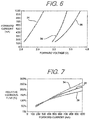
- FIG. 6 shows a graphical representation of the forward voltage versus forward current for various colors of LEDs
- FIG. 7 shows a graphical representation of the forward current versus the relative luminous flux for various colors of LEDs
- FIG. 8 shows a diagram of a lighting system in which the color temperature controllable LED lighting devices of FIGS. 1-4 may be used;
- FIG. 9 shows a lighting device having an increased power factor and reduced total harmonic distortion as contemplated by the invention.
- FIG. 10 shows a lighting device having an increased power factor and reduced total harmonic distortion as contemplated by the invention
- FIG. 11 shows a lighting device having an increased power factor and reduced total harmonic distortion as contemplated by the invention
- FIG. 12 shows a lighting device having an increased power factor and reduced total harmonic distortion as contemplated by the invention
- FIG. 13 shows a lighting device having an increased power factor and reduced total harmonic distortion as contemplated by the invention
- FIG. 14 shows a lighting device having multiple power connection leads for increasing power factor and reducing total harmonic distortion as contemplated by the invention
- FIG. 15 shows a driver for driving to the device of FIG. 13 ;
- FIG. 16 shows a lighting device having multiple power connection leads for increasing power factor and reducing total harmonic distortion as contemplated by the invention
- FIG. 17 shows a lighting device having multiple power connection leads for increasing power factor and reducing total harmonic distortion as contemplated by the invention
- FIG. 18 shows a graphical representation of an applied voltage and forward current in a known LED lighting device
- FIG. 19 shows a graphical representation of an applied voltage and forward current in an LED lighting device having an increased power factor and reduced total harmonic distortion as contemplated by the invention.
- a lighting device may include any device capable of emitting light no matter the intention. Examples of lighting devices which are contemplated by this invention include, but are not limited to, LED chips, LED packages, LED chip on board assemblies, LED assemblies or LED modules. The devices may also include any required power connections or leads or contacts, or drivers, required to provide power to the circuits and allow the circuits within the device to emit light.
- a lighting system may include multiple such devices, and some or all of the required parts to drive such a device or multiple devices, including but not limited to, power supplies, transformers, inverters, rectifiers, sensors or light emitting circuitry discussed herein.
- a lighting device may be incorporated into a lighting system or into a lamp or light bulb, it is contemplated that any required light emitting elements may be included within the system directly, whether in the form of a device as a chip or package, or as circuits within the system.
- the purposes of the devices described herein are twofold, and may be accomplished independent of each other.
- One intention of the devices described herein is to provide an LED lighting device capable of efficiently and economically emitting light having a selectable color temperature or a warm-on-dim feature when driven with AC power.
- the second intention of the devices described herein is to provide LED lighting devices which have an improved power factor and a reduced total harmonic distortion when powered with AC power.
- each LED lighting device regardless of whether the device is designed to allow color temperature control, increase power factor while reducing THD, or both.
- any known current limiting device which sets a substantially upper limit on the current which is allowed to flow through a circuit may be used with any of the circuits or devices described herein, the devices in the present application will primarily discuss using a constant current regulator (CCR), like for example those sold by ON Semiconductor or operating having the internal structures as shown in the block diagram of FIG. 1 , and a current limiting or current controlled diode (CLD).
- CCR constant current regulator
- CLD current limiting or current controlled diode
- Both CCRs and CLDs actively limit the current flowing through a particular circuit or device by substantially limiting the current to, and maintaining the current at, a threshold level once the current in a connected circuit or device has reached or exceeded a particular value.
- Using such devices is advantageous over using current limiting resistors insofar as CCRs and CLDs both cap the total current which is allowed to flow through a connected circuit or device, while the resistor only acts to reduce any every climbing current.
- the current With a current limiting resistor, as the input voltage to the circuit continues to increase, the current will likewise continue to increase without limit, albeit it at a lower value than without the resistor.
- a CCR or a CLD With a CCR or a CLD, once the current reaches a threshold maximum, the current will remain substantially constant until the input voltage is reduced, even if the input voltage continues to climb. As will be described herein, in some cases the combination of a CCR or CLD and a current limiting resistor may be beneficial or required.
- CCRs and CLDs may be used interchangeably to accomplish the goals of the devices described herein, there are differences between the devices.
- the primary difference between the devices is that CCRs, like those sold by ON Semiconductor, typically have internal transistor based control circuits and have little or no turn on voltage.
- CLDs are a form of a diode which are based in part on a JFET having a gate shorted to the power source and have a measurable turn on voltage. While the CLDs may be utilized with any of the devices described herein, it may be advantageous to use a CCR when possible in order to avoid the additional turn on voltage requirements of the CLD. However, CCRs and CLDs may be used interchangeably to accomplish the goals of the invention.
- FIGS. 2-5 show exemplary LED lighting devices capable of emitting color temperature controlled light.
- lighting device 10 includes at least two LED circuits 12 , 14 which are connected in parallel.
- Each LED circuit 12 , 14 includes one or more LEDs 16 , 18 respectively.
- Each LED circuit 12 , 14 has a different forward operating voltage and is capable of emitting light having one or more of a different color or a different wavelength than the other circuit.
- LED circuit 12 may emit amber or yellow light, while LED circuit 14 emits white or blue light.
- an active current limiting device such as a CCR or CLD, shown as CCR 20 connected in series with at least one LED 16 in first circuit 12 , may be provided.
- LED device 10 may further include connection leads 24 , 26 for connecting the device to an AC power source, like for example mains power or a switch or dimmer connected to mains power.
- AC power source like for example mains power or a switch or dimmer connected to mains power.
- device 10 and/or circuits 12 , 14 should be configured such that each circuit 12 , 14 is capable of emitting light during both a positive and negative phase of the provided AC voltage.
- a series string of LEDs 16 , 18 respectively in order to insure each circuit emits light during both the positive and negative phase of the provided AC power device 10 may include bridge rectifier 28 .
- the electrical inputs of bridge rectifier 28 may connect directly to leads 24 , 26 , while the output and return of the bridge rectifier connects to parallel circuits 12 , 14 , providing rectified AC power to each circuit. Providing the rectified power insures that each circuit is capable of emitting light during both the positive and negative when device 10 is electrically connected to an AC power source.
- connecting an LED circuit across the output of a bridge rectifier refers to connecting the LED circuit to both the output and return of the bridge rectifier, such that the circuit receives power from the output of the bridge rectifier at one end and has a return path to the return of the bridge rectifier, effectively creating a closed loop between the LED circuit and the bridge rectifier.
- While single LEDs or series strings like LED circuits 12 , 14 may require device 10 to include a bridge rectifier to utilize both phases of connected AC power, one or more of circuits 12 , 14 may be modified to use direct AC power without the requirement of rectification.
- device 10 ′ may include LED circuits 12 ′, 14 ′ where each circuit includes at least one LED 16 ′, 18 ′ respectively, connected in an antiparallel configuration.
- LED circuits 12 ′, 14 ′ are capable of emitting light during both phases of AC power without the need for rectification as each circuit has one or more LEDs configured to use both the positive and negative phase of a connected AC power source.
- circuits 12 ′, 14 ′ may be directly connected to leads 24 ′, 26 ′ as shown in FIGS. 3A and 3B without an intervening rectifier.
- more than one active current limiting device may be required. For example, as seen in FIG.
- each anti-parallel branch in circuit 12 ′ may include an active current limiting device, which may be either a CCR or CLDs 30 ′.
- an active current limiting device which may be either a CCR or CLDs 30 ′.
- back-to-back CLDs or CCRs may be attached at one end of the circuit, between circuit 12 ′ and either lead 24 ′ or 26 ′ as seen in FIG. 3B .
- both CLDs and CCRs have very low reverse breakdown characteristics, it is possible to connect CLDs or CCRs in a back-to-back fashion and realize the current protecting features of the forward-biased CLD or CCR.
- LED lighting device 10 may include circuits 12 ′′, 14 ′′ which each include at least five diodes, at least four of the diodes being LEDs 16 ′′, 18 ′′ respectively.
- LEDs 16 ′′, 18 ′′ may be configured in a bridge rectifier configuration with a fifth diode, which may be a standard diode, LED 32 ′′ as shown in circuit 12 ′′, or CLD 30 ′′ as shown in circuit 14 ′′.
- Configuring circuit 10 ′′ in a bridge configuration with a diode, LED, or active current limiting device across the output of the rectifier allows for AC power to be used during both the positive and negative phase when provided to device 10 ′′.
- circuits 12 ′′, 14 ′′ may be directly connected to connection leads 24 ′′, 26 ′′ without an intervening bridge rectifier. As seen in each circuit, unlike the circuits shown in FIG.
- a single active current limiting device may be used to protect each of circuit 12 ′′, 14 ′′ if it is located across the output of each rectifier circuit. Inasmuch as current will flow through the at least fifth diode during both the positive and negative phases, placing the active current limiting device in series with the at least fifth diode (or making the at least fifth diode the active current limiting device) will insure that current during both phases of provided AC power flows through the current limiting device, effectively limiting the current for each LED within the circuit.
- each circuit in the LED lighting device may be configured in an imbalanced bridge configuration.
- device 10 ′′′ may include circuits 12 ′′′, 14 ′′′ which each include at least diodes, at least six of which are LEDs connected in an imbalanced bridge configuration.
- the imbalanced bridge configuration will act substantially similar to, and have substantially the same characteristics as the circuits described in FIG. 4 with the added benefit of reverse breakdown protection for the LEDs forming the bridge.
- At least one additional LED is placed in series with one input LED (shown as the left branch of circuits 12 ′′′, 14 ′′′) than the other input LED, and at least one additional LED is placed in series with the opposing output LED (output LED during the opposite phase) than the aligned output LED.
- Configuring the LEDs forming the bridge in this manner helps reduce reverse breakdown of any of the LEDs in the circuit.
- the cross-connecting branch across the output of the imbalanced bridge may be a standard diode, LED 32 ′′′, CLD 30 ′′′, or some combination thereof.
- FIGS. 2-5 show each of the aforementioned circuits in pairs, it is contemplated that the circuits disclosed in each FIG. may be mixed and matched within a single device as desired.
- an LED lighting device may be made using circuits 12 , 14 ′′ or 12 ′, 14 ′′′.
- Additional circuits may further be connected in parallel within a single device, the additional circuits having a different forward operating voltage than the other connected circuits, and each additional circuit being capable of emitting light of a different color than the other connected LED circuits within the device.
- the additional circuits may be configured in any manner shown in FIGS. 2-5 and connected to or include any rectifiers or connection leads as needed to receive power and emit light during both phases of any provided AC power.
- any circuits forming an LED lighting device, along with the at least one active current limiting device, the connection leads and any required rectifiers or additional current limiting devices may be integrated on a single substrate 33 ( FIGS. 2A, 2B ), 33 ′ ( FIGS. 3A, 3B ), 33 ′′ ( FIG. 4 ), or 33 ′′′( FIG. 5 ).
- the single substrate may then be directly incorporated into a lighting system or fixture, or a lamp or light bulb as desired.
- the first method by which the light emitted by each circuit may be made different is by using a different phosphor coating on each circuit.
- the color of the LEDs used in each circuit for example LEDs 16 , 18 in FIG. 2A
- the device and circuits of FIG. 2A will be used for examples herein, it should be appreciated that the devices and circuits of FIG. 2B-5 , or any combination of circuits as discussed above, may be used in substantially the same manner to achieve substantially the same effect.
- a first circuit like circuit 12 in FIG. 2A , may include five blue LEDs and be coated in yellow or amber phosphor, while circuit 14 may include 10 blue LEDs and be coated in white phosphor. Since the first circuit includes fewer LEDs, it will begin operating first as it will have a lower turn on voltage, causing the emission of light by device 10 substantially equal to the color of the phosphor coating on circuit 12 , or yellow or amber. As the voltage provided to device 10 increases, the current flowing through circuit 12 will increase, causing the yellow or amber light to more brightly emit.
- the current flowing through circuit 12 will continue to increase until the current threshold of the at least one active current limiting device (CCR 20 ) connected in series therewith is reached. It should be noted that when only a single active current limiting device is used, it is important that the current limiting device be connected to the circuit having the lower turn on voltage in order to protect and prevent the LEDs of the circuit from overdriving as the voltage is increased to turn on and intensify the LEDs of the LED circuit having the higher turn on voltage.
- each blue LED has a turn on voltage of approximately 2.2V and will reach a nominal operating current at approximately 3.2V.
- the total turn on voltage for circuit 12 having five blue LEDs would therefore be approximately 11V (2.2V time five LEDs) while the nominal current would reached at approximately 16V.
- the turn on voltage for circuit 14 would be approximately 22V with the nominal current being reached at approximately 32V.
- LEDs 16 of circuit 12 will begin to emit light, which will be yellow or amber as a result of the phosphor coating applied to the circuit.
- the brightness of the light emitted by device 10 and circuit 12 will increase until the current flowing through circuit 12 reaches the maximum threshold of CCR 20 . If the maximum threshold current of CCR 20 is matched to nominal current of LEDs 16 , this means that the current will be capped once 16V input is reached, which is well below the turn on or voltage for nominal current in circuit 14 . Having the CCR connected in series with circuit 12 will prevent the overdrive of LEDs 16 , protecting them from early burnout resulting from overdrive or overheating as the voltage increases to turn on circuit 14 .
- LEDs 18 of circuit 14 will begin emitting white light as a result of the white phosphor coating.
- circuit 14 begins emitting white light
- the combination of yellow or amber and white light will be emitted by device 10 , causing the color temperature to begin moving towards the cooler end of the color spectrum.
- the amount of white light mixed in with the already fully emitted yellow or amber light will continue to increase as the current in circuit 14 increases, causing the color temperature to become cooler and cooler.
- an additional or second active current limiting device may be included in device 10 , CCR 22 , which may limit the current within circuit 14 to the nominal current which will be reached at approximately 32V.
- the maximum light output of device 10 will be reached at 32V along with the coolest possible temperature color. If the provided voltage increases over 32V, substantially no additional current will flow through either circuit, setting the uppermost light output of each circuit.
- circuit 14 will begin emitting less white colored light as the current will drop below nominal level. As the current in circuit 14 decreases and circuit 14 dims, the light emitted by device 10 will both dim and become warmer as the yellow or amber component will become a larger percentage of the light emitted.
- circuit 14 will turn off and the only light emitted by device 10 will come from circuit 12 , providing less light and creating a warmer yellow or amber light than when both circuit 12 and 14 were emitting light.
- the amount of each color of light emitted by the device may be controlled by controlling the input voltage, and the color temperature change and light intensity characteristics can be known and tailored to a desired output.
- the second method by which the color of the light emitted by the circuits may be made different is by using different colored LEDs in each circuit.
- the different colored LEDs will emit light of different colors, thereby causing each circuit to emit light of different colors.
- the turn on voltage characteristics of the different colored LEDs may utilized to create the difference depending on the colors of the LEDs in the circuits.
- there are two common turn on voltages for LEDs emitting colored light The first turn on voltage is approximately 1.5V for InP diodes which are typically red, amber and yellow LEDs which each reach their nominal operating current at about 2.2V.
- the second turn on voltage is approximately 2.2V for GaN diodes which are typically green or blue which reach their nominal operating current at about 3.2V.
- circuit 12 may include five LEDs 16 which emit amber light while circuit 14 may include five LEDs 18 which emit blue light and are coated in white phosphor.
- circuit 12 will begin emitting light at approximately 7.5V (again, if a CCR is connected in series, and at a higher voltage if a CLD is used) and reach nominal current at approximately 11V.
- Circuit 14 will begin emitting light at 11V but will not reach nominal current until approximately 16V.
- a low level of amber light will be emitted by device 10 until the current value of the series active current limiting device is reached.
- the active current limiting device connected in series with the LEDs of circuit 12 may be set to prevent the current from rising higher than the nominal current value for the circuit, effectively fixing the intensity of light emitted by circuit 12 while protecting the one or more LEDs therein from overdrive as the voltage increases.
- circuit 14 will begin emitting white light, cooling the color temperature of the light emitted by device 10 . The cooling will continue until either the voltage stops rising, or an active current limiting device connected in series with circuit 14 prevents the current flowing through circuit 14 from rising higher.
- circuit 14 As the voltage is decreased, the current and intensity of light emitted by circuit 14 will fall, causing the light to both dim and become warmer as the amount of light emitted from the amber LEDs will provide a greater percentage of the light emitted, creating a warmer color temperature colored light. At approximately 11V circuit 14 will turn off, and only circuit 12 and the amber LEDs will continue to emit light, creating a warmer and dimmer light as only the amber colored LEDs will be emitting light at this voltage. As the voltage continues to drop towards 7.5V, the amber LEDs will become dimmer and eventually turn off.
- FIGS. 6 and 7 show the forward operating voltage and current characteristics for red (lines indicated by 34 ), blue (lines indicated by 36 ), and green (lines indicated by 38 ) LEDs.
- These graphical representations of the forward voltage for each LED vs. the forward operating current for each LED and the forward operating current for each LED vs. the luminous flux of each LED show the operating characteristics of different colored LEDs and the importance of connecting an active current limiting device in series with at least the lowest turn on voltage in the, device. As seen in FIG. 7 , each LED color reaches approximately 100% relative luminous flux, i.e. nominal flux, at around 350 mA.
- FIG. 5 shows that red LEDs typically reach 350 mA around 2.2V (which is substantially similar for yellow or amber LEDs), blue LEDs around 3.1V, and green LEDs around 3.3V.
- red LEDs typically reach 350 mA around 2.2V (which is substantially similar for yellow or amber LEDs), blue LEDs around 3.1V, and green LEDs around 3.3V.
- each amber LED will have an approximately equal amount of voltage across it, this means that each amber LED will have approximately 3.1V-3.2V like the blue LEDs. As seen in FIG. 6 , this will cause a current of greater than 1000 mA to flow through each amber LED, and as seen in FIG. 7 cause of luminous flux of greater than 200%. This places the amber LEDs at significant risk for overheating and overdriving, causing potential premature failure of the LEDs.
- the active current limiting device By placing the active current limiting device in series with circuit 12 , the current is effectively limited at the selected value, i.e. the nominal value, and as the voltage applied to circuit 12 increases, the circuits are current limited and the one or more LEDs therein are protected. However, as seen in FIG. 6 , slight variations in voltage across each LED can cause significant increases in the current through each LED. Therefore, it may be advantageous to place an active current limiting device in series with each LED circuit in the device, in order to protect each circuit against increases or spikes in voltage.
- the power provided to device 10 may be adjusted and controlled using any means known in the art.
- device 10 may be integrated into a lighting system or fixture 40 having a dimmer switch providing the AC power to device 10 .
- dimmer switch 42 may be connected to AC power source 44 , which may be, for example, mains power or a dimmer switch connected to mains power, and may be used to control the voltage provided to device 10 .
- the dimmer switch may be any known in the art, like for example, a phase dimmer switch.
- the dimmer switch may be used to control the voltage to the circuit, causing more or less voltage to be applied to device 10 .
- circuit 12 which may have amber colored LEDs or be coated in amber phosphor may be turned on and increased in intensity.
- circuit 14 which may have blue LEDs or be coated in white phosphor, will turn on and add to the intensity of light emitted by device 10 .
- the intensity of the light emitted by device 10 will increase while the color temperature decreases.
- circuit 14 will begin decreasing in intensity, causing the circuit 12 to produce a greater percentage of the light emitted by device 10 , causing the light to have a warmer color temperature.
- AC LED devices may be further or alternatively enhanced by increasing the power factor and reducing the total harmonic distortion (THD) of the devices and light emitting circuits therein.
- TDD total harmonic distortion
- FIGS. 9-13 show LED lighting devices which have both an increased power factor and a reduced THD regardless of the color of the LEDs contained therein.
- device 100 includes at least one LED circuit, LED circuit I 02 , having at least two or more LEDs, LEDs 104 , 106 , 108 , connected in series. Connected in parallel with at least one of the LEDs, shown as LEDs 106 , is an active current limiting device, shown as CCR 110 .
- CCR 110 active current limiting device
- the turn on voltage of the CLD will at least somewhat lower the power factor gains and reduction of THD realized by using a CCR.
- the active current limiting device When connected in parallel with LEDs 106 (and any additional LEDs), the active current limiting device will provide a current bypass around the LEDs until the turn on voltage for the bypassed or shunted LEDs is reached. This will allow LEDs 104 , 108 in circuit 102 to turn on earlier than if all LEDs had to be turned on before any LEDs emit light when a voltage is applied to connection leads 112 , 114 , increasing the power factor of the circuit.
- the current flowing through LEDs 104 , 108 will be effectively limited and controlled.
- the controlled current will protect LEDs 104 , 108 as the voltage is increased to turn on LEDs 106 and substantially reduce the effect of any harmonic currents created by the non-linear reacting LEDs.
- the harmonic currents and current gains and non-linearity can be effectively reduced by controlling a threshold amount current flowing through the circuit until the additional LEDs are ready to turn on.
- all elements of any low THD LED lighting devices may be integrated on a single substrate 115 , not matter the configuration and elements included within the device.
- CCR 110 will help keep the current limited to a threshold value while LEDs 106 are bypassed, once the input voltage to device 100 reaches a level where LEDs 106 will turn on with LEDs 104 , 108 , the current will be allowed to increase unimpeded through circuit 102 as current will substantially flow through LEDs 104 , 106 , 108 without a limiter in place to maintain the current.
- a second active current limiting device shown in FIG. 9 as CLD 116 though it may advantageously be a CCR substantially eliminating any turn on voltage, and/or a current limiting resistor 118 (as shown in FIG.
- LED 10 may be connected in series with LEDs 104 , 106 , 108 and formed as part of circuit 102 .
- the additional current limiting device or current limiting resistor will help keep the current in the circuit down once LEDs 106 turn on, with the active current limiting device having the added benefit of creating an upper threshold of current flowing through the circuit.
- circuit 102 in FIGS. 9 and 10 are capable of being driven off of DC power, in order to connect and drive device 100 with AC power where THD and power factor present a greater problem, like for example mains power, device 100 may be integrated into a system or connected to a driver having a bridge rectifier, wherein rectified power is provided to circuit 102 through connection leads 112 , 114 .
- an additional circuit substantially identical to circuit 102 may be connected to circuit 102 in an anti-parallel configuration (like for example circuits 12 ′′ in FIG. 3A ) to utilize both the positive and negative phases of a supplied AC power.
- Each circuit may then have a connection to leads 112 , 114 to receive a provided AC power and operate during its respective phase.
- device 100 ′ may include a bridge rectifier 120 or 122 with circuit 102 connected across the output, either internally or externally.
- leads 112 , 114 may connect to the inputs of the rectifier, allowing the rectifier to receive AC power from an AC power source.
- Circuit 102 may then connect across the output of the rectifier, receiving and utilizing the rectified AC power.
- the bridge rectifier may be made using standard diodes, LEDs or some combination thereof.
- a THD lowering active current device may be utilized in devices having color changing LEDs as well.
- circuits 124 , 126 may be substantially identical and placed in parallel with each other. Like circuits 12 , 14 in FIG. 2A , for example, circuit 124 , 126 may each have a different forward operating voltage and be capable of emitting light of a different color. Circuits 124 , 126 may be incorporated into a system or driven by a driver having a bridge rectifier, or may be used to replace any of circuits 12 , 14 or 12 ′, 14 ′ in FIGS. 2-3 .
- the parallel current limiting device in each circuit will have substantially the same effect as described above, allowing some of the LEDs in the lower voltage circuit to turn on at a lower voltage than all of the LEDs, and reduce the harmonic distortion current resulting from the non-linearity of the LEDs.
- a portion of the LEDs in the higher voltage circuit may likewise turn on earlier, creating further temperature control as more intermediate levels of color may be realized as only some LEDs in the higher voltage circuit may turn on at first before all LEDs in the higher voltage circuit turn on.
- This configuration may allow for some or all LEDS in the lower voltage circuit to turn on, followed by some LEDs in the higher voltage circuit to turn on, beginning a cooling or warming of the light emitted by the device before all the LEDs are turned on. Eventually, shunted LEDs will turn on, further cooling or warming the light emitted by the device as it provided power and voltage increase.
- LED lighting device 200 may include LED circuit 202 having at least two LEDs, shown as LEDs 204 connected in series.
- Device 200 may include a first set of connection leads 206 , 208 which are connected to the input and output of circuit 202 , effectively providing a connection to all of the LEDs within the circuit.
- a second set of connection leads 210 , 212 may be provided as well. Connection leads 210 , 212 may provide a connection to the anode of one LED and a connection to the cathode of one LED respectively.
- Connection leads 210 , 212 may be configured, as seen in FIG. 14 , to provide a connection to less than all of the LEDs in circuit 202 .
- the first set of connection leads may be used to receive and return power for circuit 202
- the second set of connection leads may be used to connect a bypass or shunt, like for example an active current limiting device, to a subset or a portion of the LEDs forming circuit 202 .
- a bypass or shunt like for example an active current limiting device
- Each group of LEDs located either inside or outside the second set of connection leads may get categorized as a group, and may include additional connection leads as needed.
- group 214 may comprise a first set of LEDs
- group 216 may comprise a second group of LEDs
- group 218 may comprise a third group of LEDs.
- connection leads 210 , 212 may be moved to provide a connection to group 214 or group 218 .
- a third set of connection leads may also be provided to provide a connection to a second group, to create a further bypass or shunt if needed.
- connection leads 210 , 212 instead of a fixed active current limiting device allows for an end user to better control the current that will flow through circuit 202 when the LEDs between connection leads 210 , 212 are bypassed or shunted.
- the connection leads will allow an end user to select a driver or active current limiting bypass which will allow a particular amount of current to flow through the non bypassed LEDs to create a desired level of luminance from device 200 .
- Creating devices 200 with connection leads instead of bypasses also allows for different LED circuits to be connected to the same bypass or driver if the light needs of device 200 change.
- device 200 may initially include a circuit which includes 20 LEDs, 10 of which are bypassed, but now requires a circuit of 40 LEDs, 10 of which are bypassed, to provide more light.
- the end user would be able to purchase a new LED lighting device having connection leads capable of connecting some of the LEDs to an active current limiting device the end user already has.
- Such is particularly advantageous if the LEDs in the lighting device fail before the active current limiting device, as a cheaper LED lighting device may be purchased to replace the failed device and the still operational current limiting device may be utilized with the new LED lighting device.
- the driver or bypass or shunt active current limiting device fails, the LED lighting device may be disconnected from the failed driver or bypass and be re-used with a new driver or bypass.
- driver 220 may include bridge rectifier 222 and at least two active current limiting devices, shown as CCRs 224 , 226 .
- CCR 224 may be connected to an output of the bridge rectifier to control any current flowing from the bridge rectifier, while CCR 226 may be electrically unconnected to both the bridge rectifier and CCR 224 to effectively be able to provide a bypass or shunt for LEDs in circuit 202 .
- driver 220 may include three sets of driver connection leads.
- a first set of driver connection leads 228 , 230 may be utilized to provide a connection between the bridge rectifier and an AC power source.
- a second set of driver connection leads 232 , 234 may be used to connect the rectifier and associated CCR to the circuit.
- Connection lead 232 may, for example, extend from the output of CCR 224 and connect to connection lead 206 of device 200 to provide rectified AC power from rectifier 222 to circuit 202 .
- Connection lead 234 may, for example, extend from the return of rectifier 222 , and connect to connection lead 208 of circuit 202 to receive a return form circuit 202 to complete the circuit. Connecting leads 232 , 234 and 206 , 208 in this manner will provide power to each LED and active current limiting device in circuit 202 and enable the circuit to be driven.
- connection lead 236 may then connect to connection lead 210 while connection lead 238 connects to connection 212 to effectively provide a bypass around the LEDs connected between leads 210 , 212 in circuit 202 . Since CCR 226 is electrically unconnected to rectifier 222 and CCR 224 , it will effectively act as a bypass when connected across one or more of the LEDs in circuit 202 in a substantially identical manner as bypass CCR 110 does in FIG. 9 .
- the bypass connections may likewise be utilized in circuit 100 ′ with a first set of connection leads 210 ′, 212 ′ being connected to the inputs of the bridge rectifier and one or more of the LEDs 250 ′ connected across the output of the bridge rectifier being connected to a second set of connection leads 214 ′, 216 ′ in device 200 ′.
- Such a configuration would allow an end user to select a bypass of choice, with particular current limiting characteristics for driving any LEDs formed as part of the bridge rectifier 248 ′, and/or any LEDs 250 ′ connected across the output of the rectifier which are not bypassed by the parallel current limiting device.
- connection leads may also help keep the costs of the device down as end users will be able to purchase a separate active current limiting device and use it with multiple rectifier devices.
- the ratio of circuit efficiency is inversely proportional to the THD realized by the circuit as more or less LEDs are bypassed. For example, in a circuit having 20 LEDs, if five are bypassed the circuit may be highly efficient but realize a smaller reduction in THD. If 15 LEDs are bypassed, the circuit may be less efficient, but have a greater reduction in THD. It is therefore contemplated that the number of the two or more LEDs which are bypassed in any given circuit may be adjusted to match the desired characteristics of the end user of the lighting device.
- a device having fewer bypassed LEDs may be provided, while if lower THD is required a device having more LEDs bypassed may be provided.
- This inverse reaction to more or less LEDs being bypassed provides a further advantage to using devices having connection leads which attach to external active current limiting device bypasses, as it allows an end user to use a single active current limiting device to bypass different LED devices which may operate with greater efficiency or lower THD as is currently needed by the end user.
- FIGS. 18 and 19 show curve 240 which represents an AC input voltage to a known LED lighting device not using an active current limiting bypass and instead using a current limiting resistor, for example, and the current response curve 242 of the same device.
- FIG. 19 shows the same two curves, curve 244 showing an AC input voltage and curve 246 showing current, when a device having an identical number of LEDs to the circuit producing the curve in FIG. 18 is used with an active current limiting bypass as described herein. As seen in FIGS.
- utilizing the bypass in the present invention increases power factor, as current begins flowing through the device much closer to the voltage turn on point when a bypass is used than when it is not. This better power factor is the result of the device having the bypass circuit beginning to emit light much earlier as only enough voltage to turn on the non-bypasssed (and CLD if used instead of a CCR) is required for the device to begin emitting light. If each circuit includes 20 LEDs which each turn on at 2.2V, for example, and 10 LEDs are bypassed in a circuit and device as described herein, it will turn on once the provided AC voltage reaches 22V whereas the device not having the bypass will not turn on until provided AC voltage reaches 44V.
- the bypass allows the device to turn on much earlier, allowing light to be emitted much earlier in the provided voltage waveform, i.e. increasing the power factor.
- the current response using a bypass also has a substantially reduced THD, as the current waveform better approximates the provided AC voltage.
Abstract
Description
Claims (21)
Priority Applications (3)
| Application Number | Priority Date | Filing Date | Title |
|---|---|---|---|
| US16/440,884 US10757783B2 (en) | 2011-12-02 | 2019-06-13 | Color temperature controlled and low THD LED lighting devices and systems and methods of driving the same |
| US17/001,074 US11284491B2 (en) | 2011-12-02 | 2020-08-24 | Color temperature controlled and low THD LED lighting devices and systems and methods of driving the same |
| US17/699,873 US20220217825A1 (en) | 2011-12-02 | 2022-03-21 | Color temperature controlled and low thd led lighting devices and systems and methods of driving the same |
Applications Claiming Priority (8)
| Application Number | Priority Date | Filing Date | Title |
|---|---|---|---|
| US201161630025P | 2011-12-02 | 2011-12-02 | |
| US201161570200P | 2011-12-13 | 2011-12-13 | |
| PCT/US2012/051531 WO2013026053A1 (en) | 2011-08-18 | 2012-08-20 | Devices and systems having ac led circuits and methods of driving the same |
| PCT/US2012/067623 WO2013082609A1 (en) | 2011-12-02 | 2012-12-03 | Color temperature controlled and low thd led lighting devices and systems and methods of driving the same |
| US201414362173A | 2014-06-02 | 2014-06-02 | |
| US15/005,108 US9516716B2 (en) | 2011-12-02 | 2016-01-25 | Color temperature controlled and low THD LED lighting devices and systems and methods of driving the same |
| US15/369,218 US10349479B2 (en) | 2011-12-02 | 2016-12-05 | Color temperature controlled and low THD LED lighting devices and systems and methods of driving the same |
| US16/440,884 US10757783B2 (en) | 2011-12-02 | 2019-06-13 | Color temperature controlled and low THD LED lighting devices and systems and methods of driving the same |
Related Parent Applications (1)
| Application Number | Title | Priority Date | Filing Date |
|---|---|---|---|
| US15/369,218 Continuation US10349479B2 (en) | 2011-12-02 | 2016-12-05 | Color temperature controlled and low THD LED lighting devices and systems and methods of driving the same |
Related Child Applications (1)
| Application Number | Title | Priority Date | Filing Date |
|---|---|---|---|
| US17/001,074 Continuation US11284491B2 (en) | 2011-12-02 | 2020-08-24 | Color temperature controlled and low THD LED lighting devices and systems and methods of driving the same |
Publications (2)
| Publication Number | Publication Date |
|---|---|
| US20190297697A1 US20190297697A1 (en) | 2019-09-26 |
| US10757783B2 true US10757783B2 (en) | 2020-08-25 |
Family
ID=48536168
Family Applications (6)
| Application Number | Title | Priority Date | Filing Date |
|---|---|---|---|
| US14/362,173 Active US9247597B2 (en) | 2011-12-02 | 2012-12-03 | Color temperature controlled and low THD LED lighting devices and systems and methods of driving the same |
| US15/005,108 Active US9516716B2 (en) | 2011-12-02 | 2016-01-25 | Color temperature controlled and low THD LED lighting devices and systems and methods of driving the same |
| US15/369,218 Active US10349479B2 (en) | 2011-12-02 | 2016-12-05 | Color temperature controlled and low THD LED lighting devices and systems and methods of driving the same |
| US16/440,884 Active US10757783B2 (en) | 2011-12-02 | 2019-06-13 | Color temperature controlled and low THD LED lighting devices and systems and methods of driving the same |
| US17/001,074 Active US11284491B2 (en) | 2011-12-02 | 2020-08-24 | Color temperature controlled and low THD LED lighting devices and systems and methods of driving the same |
| US17/699,873 Pending US20220217825A1 (en) | 2011-12-02 | 2022-03-21 | Color temperature controlled and low thd led lighting devices and systems and methods of driving the same |
Family Applications Before (3)
| Application Number | Title | Priority Date | Filing Date |
|---|---|---|---|
| US14/362,173 Active US9247597B2 (en) | 2011-12-02 | 2012-12-03 | Color temperature controlled and low THD LED lighting devices and systems and methods of driving the same |
| US15/005,108 Active US9516716B2 (en) | 2011-12-02 | 2016-01-25 | Color temperature controlled and low THD LED lighting devices and systems and methods of driving the same |
| US15/369,218 Active US10349479B2 (en) | 2011-12-02 | 2016-12-05 | Color temperature controlled and low THD LED lighting devices and systems and methods of driving the same |
Family Applications After (2)
| Application Number | Title | Priority Date | Filing Date |
|---|---|---|---|
| US17/001,074 Active US11284491B2 (en) | 2011-12-02 | 2020-08-24 | Color temperature controlled and low THD LED lighting devices and systems and methods of driving the same |
| US17/699,873 Pending US20220217825A1 (en) | 2011-12-02 | 2022-03-21 | Color temperature controlled and low thd led lighting devices and systems and methods of driving the same |
Country Status (2)
| Country | Link |
|---|---|
| US (6) | US9247597B2 (en) |
| WO (1) | WO2013082609A1 (en) |
Cited By (8)
| Publication number | Priority date | Publication date | Assignee | Title |
|---|---|---|---|---|
| US11284491B2 (en) | 2011-12-02 | 2022-03-22 | Lynk Labs, Inc. | Color temperature controlled and low THD LED lighting devices and systems and methods of driving the same |
| US11297705B2 (en) | 2007-10-06 | 2022-04-05 | Lynk Labs, Inc. | Multi-voltage and multi-brightness LED lighting devices and methods of using same |
| US11317495B2 (en) | 2007-10-06 | 2022-04-26 | Lynk Labs, Inc. | LED circuits and assemblies |
| US11528792B2 (en) | 2004-02-25 | 2022-12-13 | Lynk Labs, Inc. | High frequency multi-voltage and multi-brightness LED lighting devices |
| US11566759B2 (en) | 2017-08-31 | 2023-01-31 | Lynk Labs, Inc. | LED lighting system and installation methods |
| US11638336B2 (en) | 2004-02-25 | 2023-04-25 | Lynk Labs, Inc. | AC light emitting diode and AC LED drive methods and apparatus |
| US11678420B2 (en) | 2004-02-25 | 2023-06-13 | Lynk Labs, Inc. | LED lighting system |
| US11953167B2 (en) | 2011-08-18 | 2024-04-09 | Lynk Labs, Inc. | Devices and systems having AC LED circuits and methods of driving the same |
Families Citing this family (43)
| Publication number | Priority date | Publication date | Assignee | Title |
|---|---|---|---|---|
| US10091842B2 (en) | 2004-02-25 | 2018-10-02 | Lynk Labs, Inc. | AC light emitting diode and AC LED drive methods and apparatus |
| US10154551B2 (en) | 2004-02-25 | 2018-12-11 | Lynk Labs, Inc. | AC light emitting diode and AC LED drive methods and apparatus |
| US10506674B2 (en) | 2004-02-25 | 2019-12-10 | Lynk Labs, Inc. | AC light emitting diode and AC LED drive methods and apparatus |
| US8835945B2 (en) * | 2013-01-11 | 2014-09-16 | Lighting Science Group Corporation | Serially-connected light emitting diodes, methods of forming same, and luminaires containing same |
| US8710754B2 (en) * | 2011-09-12 | 2014-04-29 | Juno Manufacturing Llc | Dimmable LED light fixture having adjustable color temperature |
| US9345112B2 (en) | 2013-03-09 | 2016-05-17 | Chia-Teh Chen | Microcontroller-based multifunctional electronic switch and lighting apparatus having the same |
| US11699994B2 (en) | 2012-10-15 | 2023-07-11 | Vaxcel International Co., Ltd. | Method of tuning light color temperature for LED lighting device and application thereof |
| US20230262854A1 (en) * | 2012-11-13 | 2023-08-17 | Lynk Labs, Inc. | Ac light emitting diode and ac led drive methods and apparatus |
| US9179511B2 (en) * | 2013-07-08 | 2015-11-03 | Panasonic Intellectual Property Management Co., Ltd. | Light-emitting device, and light source for lighting and lighting apparatus using the same |
| FR3018987A1 (en) * | 2014-03-20 | 2015-09-25 | Alpha Test | LED LIGHTING SYSTEM OF LIGHT TYPE, IN PARTICULAR. |
| KR102206282B1 (en) | 2014-09-05 | 2021-01-22 | 서울반도체 주식회사 | Led driving circuit and lighting device |
| US9763298B2 (en) * | 2015-03-24 | 2017-09-12 | Hubbell Incorporated | Voltage balancing current controlled LED circuit |
| KR102458620B1 (en) * | 2015-07-02 | 2022-10-25 | 루미리즈 홀딩 비.브이. | LED lighting device |
| KR102443035B1 (en) | 2015-09-02 | 2022-09-16 | 삼성전자주식회사 | Led driving apparatus and light apparatus including the same |
| US20170150560A1 (en) * | 2015-11-22 | 2017-05-25 | Jlj, Inc. | Colorful led light string |
| CA2951301C (en) | 2015-12-09 | 2019-03-05 | Abl Ip Holding Llc | Color mixing for solid state lighting using direct ac drives |
| US11686459B2 (en) | 2015-12-15 | 2023-06-27 | Wangs Alliance Corporation | LED lighting methods and apparatus |
| US10941924B2 (en) | 2015-12-15 | 2021-03-09 | Wangs Alliance Corporation | LED lighting methods and apparatus |
| US10330294B2 (en) | 2015-12-15 | 2019-06-25 | Wangs Alliance Corporation | LED lighting methods and apparatus |
| US9892693B1 (en) | 2016-02-19 | 2018-02-13 | Cooper Technologies Company | Configurable lighting system |
| US10117300B2 (en) | 2016-02-19 | 2018-10-30 | Cooper Technologies Company | Configurable lighting system |
| US9820350B2 (en) | 2016-02-19 | 2017-11-14 | Cooper Technologies Company | Configurable lighting system |
| US10733944B2 (en) | 2016-02-19 | 2020-08-04 | Signify Holding B.V. | Configurable modes for lighting systems |
| CN105682296A (en) * | 2016-03-21 | 2016-06-15 | 江门市蓬江区广达电器有限公司 | Forward-reverse connection type LED lamp string |
| US10136485B1 (en) * | 2016-03-30 | 2018-11-20 | Cooledge Lighting Inc. | Methods for adjusting the light output of illumination systems |
| US10667362B1 (en) * | 2016-03-30 | 2020-05-26 | Cooledge Lighting Inc. | Methods of operating lighting systems with controllable illumination |
| US9854637B2 (en) | 2016-05-18 | 2017-12-26 | Abl Ip Holding Llc | Method for controlling a tunable white fixture using a single handle |
| CN106332369B (en) * | 2016-10-10 | 2018-11-06 | 深圳迪亚士照明科技有限公司 | LED light bar light modulation toning circuit temperature |
| US10297584B2 (en) * | 2017-03-21 | 2019-05-21 | Light To Form, Llc | Chip on board LED device and method |
| KR102400151B1 (en) | 2017-05-31 | 2022-05-20 | 서울반도체 주식회사 | Led package set and led bulb including the same |
| US11812525B2 (en) * | 2017-06-27 | 2023-11-07 | Wangs Alliance Corporation | Methods and apparatus for controlling the current supplied to light emitting diodes |
| US10502404B1 (en) | 2018-06-21 | 2019-12-10 | Eaton Intelligent Power Limited | Junction box-driver assembly for direct mount luminaires |
| CN109068447A (en) * | 2018-09-05 | 2018-12-21 | 上海强凌电子有限公司 | LED filament and LED light |
| US10874006B1 (en) | 2019-03-08 | 2020-12-22 | Abl Ip Holding Llc | Lighting fixture controller for controlling color temperature and intensity |
| CN110087365A (en) * | 2019-05-24 | 2019-08-02 | 深圳迪亚士照明科技有限公司 | A kind of brightness colour temperature synchronous adjustment flexible LED lamp bar circuit and soft light bar |
| US10728979B1 (en) | 2019-09-30 | 2020-07-28 | Abl Ip Holding Llc | Lighting fixture configured to provide multiple lighting effects |
| EP3823420A1 (en) * | 2019-11-18 | 2021-05-19 | Lumileds Holding B.V. | Led lighting package |
| CN110985903B (en) | 2019-12-31 | 2020-08-14 | 江苏舒适照明有限公司 | Lamp module |
| US11598517B2 (en) | 2019-12-31 | 2023-03-07 | Lumien Enterprise, Inc. | Electronic module group |
| CN111503556B (en) | 2020-04-23 | 2020-11-27 | 江苏舒适照明有限公司 | Spotlight structure |
| US11913608B2 (en) | 2020-11-03 | 2024-02-27 | Signify Holding, B.V. | LED filament arrangement |
| US11812532B2 (en) | 2021-05-27 | 2023-11-07 | Wangs Alliance Corporation | Multiplexed segmented lighting lamina |
| US11802682B1 (en) | 2022-08-29 | 2023-10-31 | Wangs Alliance Corporation | Modular articulating lighting |
Citations (111)
| Publication number | Priority date | Publication date | Assignee | Title |
|---|---|---|---|---|
| US3869641A (en) | 1972-06-21 | 1975-03-04 | Monsanto Co | AC Responsive led pilot light circuitry |
| US4218627A (en) | 1978-09-01 | 1980-08-19 | Polaroid Corporation | Electrical mean square voltage sensor |
| US4271408A (en) | 1978-10-17 | 1981-06-02 | Stanley Electric Co., Ltd. | Colored-light emitting display |
| US4298869A (en) | 1978-06-29 | 1981-11-03 | Zaidan Hojin Handotai Kenkyu Shinkokai | Light-emitting diode display |
| US4506318A (en) | 1983-04-22 | 1985-03-19 | Nilssen Ole K | Inverter with controllable RMS output voltage magnitude |
| US4535203A (en) | 1982-12-08 | 1985-08-13 | Siliconix Limited | Bridge rectifier circuit |
| US5180952A (en) | 1983-04-22 | 1993-01-19 | Nilssen Ole K | Electronic track lighting system |
| US5442258A (en) | 1994-05-04 | 1995-08-15 | Hakuyo Denkyu Kabushiki Kaisha | LED lamp device |
| JPH08137429A (en) | 1994-11-14 | 1996-05-31 | Seibu Electric & Mach Co Ltd | Display device |
| US5699218A (en) | 1996-01-02 | 1997-12-16 | Kadah; Andrew S. | Solid state/electromechanical hybrid relay |
| US5790013A (en) | 1995-10-04 | 1998-08-04 | Hauck; Lane T. | Electronic novelty device and method of using same |
| JPH1116683A (en) | 1997-06-23 | 1999-01-22 | Masanori Minato | Light emitting display device |
| WO1999020085A1 (en) | 1997-10-10 | 1999-04-22 | Se Kang Electric Co., Ltd. | Electric lamp circuit and structure using light emitting diodes |
| JPH11330561A (en) | 1998-05-14 | 1999-11-30 | Oki Electric Ind Co Ltd | Led luminaire |
| US6107744A (en) | 1995-11-29 | 2000-08-22 | Bavaro; Joseph P. | Back-up electrical systems |
| US6157551A (en) | 1998-11-09 | 2000-12-05 | Lightech Electronics Industries Ltd. | Electronic transformer for lighting |
| US6380693B1 (en) | 1999-08-11 | 2002-04-30 | Patent-Treuhand-Gesellschaft Fuer Elektrische Gluehlampen Mbh | Apparatus for operating at least one light-emitting diode |
| US20020060526A1 (en) | 2000-02-11 | 2002-05-23 | Jos Timmermans | Light tube and power supply circuit |
| EP1215944A1 (en) | 2000-12-14 | 2002-06-19 | General Electric Company | Light emitting diode power supply |
| US6412971B1 (en) | 1998-01-02 | 2002-07-02 | General Electric Company | Light source including an array of light emitting semiconductor devices and control method |
| US20030043611A1 (en) | 2000-03-17 | 2003-03-06 | Tridonicatco Gmbh & Co. Kg | Drive for light-emitting diodes |
| US6580228B1 (en) | 2000-08-22 | 2003-06-17 | Light Sciences Corporation | Flexible substrate mounted solid-state light sources for use in line current lamp sockets |
| US20030122502A1 (en) | 2001-12-28 | 2003-07-03 | Bernd Clauberg | Light emitting diode driver |
| US20030169014A1 (en) | 2002-03-06 | 2003-09-11 | Kadah Andrew S. | Universal energy regulating controller circuit |
| US20030175004A1 (en) | 2002-02-19 | 2003-09-18 | Garito Anthony F. | Optical polymer nanocomposites |
| US20040080941A1 (en) | 2002-10-24 | 2004-04-29 | Hongxing Jiang | Light emitting diodes for high AC voltage operation and general lighting |
| US20040105264A1 (en) | 2002-07-12 | 2004-06-03 | Yechezkal Spero | Multiple Light-Source Illuminating System |
| US6781570B1 (en) | 2000-11-09 | 2004-08-24 | Logitech Europe S.A. | Wireless optical input device |
| US6781329B2 (en) * | 1997-08-26 | 2004-08-24 | Color Kinetics Incorporated | Methods and apparatus for illumination of liquids |
| US20040183380A1 (en) | 2003-03-07 | 2004-09-23 | Toko, Inc. | Switching constant-current power supply system |
| US20040189218A1 (en) | 2002-11-19 | 2004-09-30 | Leong Susan J. | Led retrofit lamp |
| US20040201988A1 (en) | 1999-02-12 | 2004-10-14 | Fiber Optic Designs, Inc. | LED light string and arrays with improved harmonics and optimized power utilization |
| US20040206970A1 (en) | 2003-04-16 | 2004-10-21 | Martin Paul S. | Alternating current light emitting device |
| US20050110426A1 (en) | 2003-11-21 | 2005-05-26 | Chiliang Shao | Structure for LED lighting chain |
| US20050173990A1 (en) | 2002-02-28 | 2005-08-11 | Andersen James N. | One wire self referencing circuits for providing power and data |
| US20050230600A1 (en) | 2004-03-30 | 2005-10-20 | Olson Steven J | LED array having array-based LED detectors |
| US20060038542A1 (en) | 2003-12-23 | 2006-02-23 | Tessera, Inc. | Solid state lighting device |
| US7019062B2 (en) | 2000-05-17 | 2006-03-28 | General Electric | High performance thermoplastic compositions with improved melt flow properties |
| US7019662B2 (en) | 2003-07-29 | 2006-03-28 | Universal Lighting Technologies, Inc. | LED drive for generating constant light output |
| US7038400B2 (en) | 2004-03-12 | 2006-05-02 | Juno Manufacturing, Inc. | Constant current Class 3 lighting system |
| US20060103913A1 (en) | 1994-12-22 | 2006-05-18 | Handschy Mark A | Optics arrangements including light source arrangements for an active matrix liquid crystal image generator |
| US7053560B1 (en) | 2003-11-17 | 2006-05-30 | Dr. Led (Holdings), Inc. | Bi-directional LED-based light |
| US20060138971A1 (en) | 2004-12-27 | 2006-06-29 | Top Union Globaltek Inc | LED driving circuit |
| US20060158130A1 (en) | 2004-12-22 | 2006-07-20 | Sony Corporation | Illumination apparatus and image display apparatus |
| US7081722B1 (en) | 2005-02-04 | 2006-07-25 | Kimlong Huynh | Light emitting diode multiphase driver circuit and method |
| US20070069663A1 (en) | 2005-05-27 | 2007-03-29 | Burdalski Robert J | Solid state LED bridge rectifier light engine |
| US7204607B2 (en) | 2003-09-16 | 2007-04-17 | Matsushita Electric Industrial Co., Ltd. | LED lamp |
| WO2007093938A1 (en) | 2006-02-14 | 2007-08-23 | Koninklijke Philips Electronics N.V. | Current driving of leds |
| US7288902B1 (en) | 2007-03-12 | 2007-10-30 | Cirrus Logic, Inc. | Color variations in a dimmable lighting device with stable color temperature light sources |
| US20070273299A1 (en) | 2004-02-25 | 2007-11-29 | Michael Miskin | AC light emitting diode and AC LED drive methods and apparatus |
| US20080094837A1 (en) | 2006-10-24 | 2008-04-24 | Ellenby Technologies, Inc. | LED Lamp Suitable as a Replacement for Fluorescent Lamp in Vending Machines |
| US20080116816A1 (en) | 2006-11-08 | 2008-05-22 | Neuman Robert C | Limited flicker light emitting diode string |
| US20080136347A1 (en) | 2005-05-13 | 2008-06-12 | Industrial Technology Research Institute | Alternating Current Light Emitting Device |
| US20080158915A1 (en) | 2006-12-30 | 2008-07-03 | Advanced Analogic Technologies, Inc. | High-efficiency DC/DC voltage converter including down inductive switching pre-regulator and capacitive switching post-converter |
| US20080203405A1 (en) | 2005-08-05 | 2008-08-28 | Johannes Otto Rooymans | Method for Preparing an Electric Circuit Comprising Multiple Leds |
| US20080203936A1 (en) | 2007-02-28 | 2008-08-28 | Mitsuru Mariyama | Led drive circuit and led light-emitting device |
| US20080211421A1 (en) | 2005-06-28 | 2008-09-04 | Seoul Opto Device Co., Ltd. | Light Emitting Device For Ac Power Operation |
| US20080218098A1 (en) | 2005-12-16 | 2008-09-11 | Seoul Opto Device Co., Ltd. | Light Emitting Device with Light Emitting Cells Arrayed |
| WO2008124701A2 (en) | 2007-04-06 | 2008-10-16 | Sunovia Energe Technologies, Inc. | Light unit with internal power failure detection |
| US20090160361A1 (en) | 2005-11-16 | 2009-06-25 | Rohm Co., Ltd. | Light emitting device |
| US20090174337A1 (en) | 2007-10-06 | 2009-07-09 | Lynk Labs, Inc. | LED circuits and assemblies |
| US20090221185A1 (en) | 2004-04-02 | 2009-09-03 | Siemens Aktiengesellschaft | Plug-In Adapter |
| US20090295300A1 (en) | 2008-02-08 | 2009-12-03 | Purespectrum, Inc | Methods and apparatus for a dimmable ballast for use with led based light sources |
| US20100039794A1 (en) | 2008-08-15 | 2010-02-18 | Lumination Llc. | Traffic led lamp with internal circuit backup system |
| US20100109558A1 (en) | 2008-11-03 | 2010-05-06 | Tong Fatt Chew | AC to DC LED illumination devices, systems and methods |
| US7748877B1 (en) | 2004-10-05 | 2010-07-06 | Colby Steven M | Multi-mode bulb |
| US20100207534A1 (en) * | 2007-10-09 | 2010-08-19 | Philips Solid-State Lighting Solutions, Inc. | Integrated led-based luminare for general lighting |
| WO2010106375A2 (en) | 2009-03-19 | 2010-09-23 | Juice Technology Limited | Electrical systems |
| US7808189B2 (en) | 2004-09-30 | 2010-10-05 | Osram Opto Semiconductors Gmbh | LED circuit arrangement having a diode rectifier |
| WO2010138211A1 (en) | 2009-05-28 | 2010-12-02 | Lynk Labs, Inc. | Multi-voltage and multi-brightness led lighting devices and methods of using same |
| US20100308743A1 (en) | 2009-06-08 | 2010-12-09 | National Cheng Kung University | Light Emitting Diode Driving Device |
| US20100308739A1 (en) | 2009-06-04 | 2010-12-09 | Exclara Inc. | Apparatus, Method and System for Providing AC Line Power to Lighting Devices |
| US20100320934A1 (en) * | 2009-06-22 | 2010-12-23 | Da Liu | Circuits and methods for driving a load with power factor correction function |
| US7859196B2 (en) | 2007-04-25 | 2010-12-28 | American Bright Lighting, Inc. | Solid state lighting apparatus |
| US20110057572A1 (en) | 2009-09-08 | 2011-03-10 | Denovo Lighting, L.L.C. | Voltage regulating devices in LED lamps with multiple power sources |
| US20110183368A1 (en) * | 2008-05-22 | 2011-07-28 | Fionia Lighting Aps | Method and apparatus for using light emitting diodes in a greenhouse setting |
| US20110260622A1 (en) | 2010-04-23 | 2011-10-27 | Teknoware Oy | Led tube and lighting fixture arrangement |
| US20110298393A1 (en) | 2008-11-03 | 2011-12-08 | Gt Biomescilt Light Limited | Ac to dc led illumination devices, systems and method |
| US20120043897A1 (en) | 2009-05-01 | 2012-02-23 | Link Labs, Inc. | Led circuits and assemblies |
| US20120049742A1 (en) | 2010-08-27 | 2012-03-01 | American Bright Lighting, Inc. | Solid state lighting driver with thdi bypass circuit |
| US20120081009A1 (en) | 2009-06-04 | 2012-04-05 | Exclara Inc. | Apparatus, Method and System for Providing AC Line Power to Lighting Devices |
| US8193730B2 (en) | 2008-06-12 | 2012-06-05 | 3M Innovative Properties Company | Dimmer and illumination apparatus with amplitude ordered illumination of multiple strings of multiple color light emitting devices |
| US8198819B2 (en) | 2008-09-17 | 2012-06-12 | Switch Bulb Company, Inc. | 3-way LED bulb |
| US20120228529A1 (en) * | 2009-11-16 | 2012-09-13 | Christopher Scott Trewin | Contactless coupling and method for use with an electrical appliance |
| US20120268008A1 (en) | 2009-10-19 | 2012-10-25 | Lynk Labs, Inc. | LED Circuits and Assemblies |
| US20120293083A1 (en) | 2004-02-25 | 2012-11-22 | Lynk Labs, Inc. | High Frequency Multi-Voltage And Multi-Brightness LED Lighting Devices And Systems And Methods Of Using Same |
| US20130002167A1 (en) * | 2011-06-28 | 2013-01-03 | Van De Ven Antony P | Variable correlated color temperature luminary constructs |
| US20130049602A1 (en) | 2011-08-25 | 2013-02-28 | Abl Ip Holding Llc | Tunable white luminaire |
| US20130069535A1 (en) | 2011-09-16 | 2013-03-21 | Cree, Inc. | Solid-state lighting apparatus and methods using energy storage |
| US20130082611A1 (en) * | 2011-08-29 | 2013-04-04 | Texas Instruments Incorporated | Feed forward controlled voltage to current source for led driver |
| US20130093325A1 (en) * | 2011-10-17 | 2013-04-18 | Eco Lumens, Llc | Light emitting diode (led) lighting systems and methods |
| US20130119896A1 (en) | 2010-06-28 | 2013-05-16 | Toshiba Lighting & Technology Corporation | Straight tube led lamp, lamp socket set, and lighting fixture |
| US8476836B2 (en) | 2010-05-07 | 2013-07-02 | Cree, Inc. | AC driven solid state lighting apparatus with LED string including switched segments |
| US8573797B2 (en) | 2008-01-25 | 2013-11-05 | Eveready Battery Company, Inc. | Lighting device |
| US8614103B2 (en) | 2006-10-27 | 2013-12-24 | Lpath, Inc. | Compositions and methods for treating sphingosine-1-phosphate (S1P) related ocular diseases and conditions |
| US8643308B2 (en) | 2009-08-14 | 2014-02-04 | Once Innovations, Inc. | Spectral shift control for dimmable AC LED lighting |
| US20140063837A1 (en) * | 2012-09-04 | 2014-03-06 | Cree, Inc. | Led based lighting system |
| US20140084801A1 (en) | 2012-09-21 | 2014-03-27 | Cree, Inc. | Active current limiting for lighting apparatus |
| US20140111091A1 (en) | 2009-08-14 | 2014-04-24 | Zdenko Grajcar | Spectral shift control for dimmable ac led lighting |
| US8710754B2 (en) | 2011-09-12 | 2014-04-29 | Juno Manufacturing Llc | Dimmable LED light fixture having adjustable color temperature |
| US20140159584A1 (en) | 2009-08-14 | 2014-06-12 | Once Innovations, Inc. | Spectral shift control and methods for dimmable ac led lighting |
| US8762562B2 (en) | 2008-06-12 | 2014-06-24 | Apple Inc. | Network-assisted remote media listening |
| US20140239809A1 (en) | 2011-08-18 | 2014-08-28 | Lynk Labs, Inc. | Devices and systems having ac led circuits and methods of driving the same |
| US20140285102A1 (en) | 2013-03-19 | 2014-09-25 | Praveen K. Jain | High power factor, electrolytic capacitor-less driver circuit for light-emitting diode lamps |
| US20140361696A1 (en) | 2012-01-20 | 2014-12-11 | Osram Sylvania Inc. | Lighting systems with uniform led brightness |
| US20150115823A1 (en) | 2013-10-31 | 2015-04-30 | Juno Manufacturing, LLC | Analog circuit for color change dimming |
| US20150216006A1 (en) | 2014-01-29 | 2015-07-30 | American Bright Lighting, Inc. | Multi-stage led lighting systems |
| US9198237B2 (en) | 2004-02-25 | 2015-11-24 | Lynk Labs, Inc. | LED lighting system |
| US9247597B2 (en) | 2011-12-02 | 2016-01-26 | Lynk Labs, Inc. | Color temperature controlled and low THD LED lighting devices and systems and methods of driving the same |
| US20160095180A1 (en) | 2004-02-25 | 2016-03-31 | Lynk Labs, Inc. | LED Lighting System |
| WO2016164928A1 (en) | 2015-04-09 | 2016-10-13 | Lynk Labs, Inc. | Low flicker ac driven led lighting system, drive method and apparatus |
Family Cites Families (282)
| Publication number | Priority date | Publication date | Assignee | Title |
|---|---|---|---|---|
| US3582932A (en) | 1968-10-11 | 1971-06-01 | Bell Inc F W | Magnetic-field-responsive proximity detector apparatus |
| US3712706A (en) | 1971-01-04 | 1973-01-23 | American Cyanamid Co | Retroreflective surface |
| US3821662A (en) | 1971-03-12 | 1974-06-28 | Bell Telephone Labor Inc | Semiconductor laser employing iii-vi compounds |
| US3981023A (en) | 1974-09-16 | 1976-09-14 | Northern Electric Company Limited | Integral lens light emitting diode |
| US4104562A (en) | 1976-11-17 | 1978-08-01 | Traffic Systems, Inc. | Traffic light dimmer system |
| DE2716143A1 (en) | 1977-04-12 | 1978-10-19 | Siemens Ag | LIGHT-EMITTING SEMI-CONDUCTOR COMPONENT |
| US4153876A (en) | 1977-04-27 | 1979-05-08 | Texas Instruments Incorporated | Charge transfer device radio system |
| US4246533A (en) | 1979-05-25 | 1981-01-20 | Bing Chiang | Proximity controlled power switching circuit |
| US4350973A (en) | 1979-07-23 | 1982-09-21 | Honeywell Information Systems Inc. | Receiver apparatus for converting optically encoded binary data to electrical signals |
| US5014052A (en) | 1983-04-21 | 1991-05-07 | Bourse Trading Company, Ltd. | Traffic signal control for emergency vehicles |
| US4563592A (en) | 1983-10-13 | 1986-01-07 | Lutron Electronics Co. Inc. | Wall box dimmer switch with plural remote control switches |
| US4654880A (en) | 1983-12-09 | 1987-03-31 | Minnesota Mining And Manufacturing Company | Signal transmission system |
| US4573766A (en) | 1983-12-19 | 1986-03-04 | Cordis Corporation | LED Staggered back lighting panel for LCD module |
| USRE33285E (en) | 1984-06-13 | 1990-07-31 | Touch controlled switch for a lamp or the like | |
| SE8406107L (en) | 1984-12-03 | 1986-06-04 | Surtevall Trading Ab | DEVICE FOR LOADING A FORMULA AGAINST A STRAP, AXLE OR SIMILAR |
| JPH0647300B2 (en) | 1984-12-13 | 1994-06-22 | 三洋電機株式会社 | Image forming device |
| US4691341A (en) | 1985-03-18 | 1987-09-01 | General Electric Company | Method of transferring digital information and street lighting control system |
| US4656398A (en) | 1985-12-02 | 1987-04-07 | Michael Anthony J | Lighting assembly |
| US4797651A (en) | 1986-04-28 | 1989-01-10 | Karel Havel | Multicolor comparator of digital signals |
| US5010459A (en) | 1986-07-17 | 1991-04-23 | Vari-Lite, Inc. | Console/lamp unit coordination and communication in lighting systems |
| GB2202414A (en) | 1987-03-10 | 1988-09-21 | Oxley Dev Co Ltd | Transmission of power and/or data |
| US4780621A (en) | 1987-06-30 | 1988-10-25 | Frank J. Bartleucci | Ornamental lighting system |
| US4816698A (en) | 1987-11-18 | 1989-03-28 | Hook Glen C | Touch control circuit for incandescent lamps and the like |
| US4962347A (en) | 1988-02-25 | 1990-10-09 | Strategic Energy, Ltd. | Flashlight with battery tester |
| JPH01166400U (en) | 1988-05-10 | 1989-11-21 | ||
| US5028859A (en) | 1989-06-05 | 1991-07-02 | Motorola, Inc. | Multiple battery, multiple rate battery charger |
| US5293494A (en) | 1989-06-23 | 1994-03-08 | Kabushiki Kaisha Toshiba | Personal computer for setting, in a software setup operation normal/reverse display, connection of an external device, and an automatic display off function |
| EP0464240B1 (en) | 1990-07-03 | 1995-09-27 | Siemens Aktiengesellschaft | Circuit for a blocking oscillator converter working in the auto-oscillation mode |
| KR0133549B1 (en) | 1990-12-18 | 1998-04-23 | 프랭크린 씨. 웨이스 | Laptop computer with pomlest and keyboard and cursor |
| US5408330A (en) | 1991-03-25 | 1995-04-18 | Crimtec Corporation | Video incident capture system |
| US5267134A (en) | 1991-09-19 | 1993-11-30 | Aziz Banayan | Voltage and frequency converter device |
| US5193539A (en) | 1991-12-18 | 1993-03-16 | Alfred E. Mann Foundation For Scientific Research | Implantable microstimulator |
| GB9204362D0 (en) | 1992-02-28 | 1992-04-08 | Kenholme Appliances Electrical | Fuel and/or flame effect |
| US5457450A (en) | 1993-04-29 | 1995-10-10 | R & M Deese Inc. | LED traffic signal light with automatic low-line voltage compensating circuit |
| US6853293B2 (en) | 1993-05-28 | 2005-02-08 | Symbol Technologies, Inc. | Wearable communication system |
| US5652609A (en) | 1993-06-09 | 1997-07-29 | J. David Scholler | Recording device using an electret transducer |
| US5519263A (en) | 1993-08-19 | 1996-05-21 | Lamson & Sessions Co., The | Three-way toggle dimmer switch |
| US5430609A (en) | 1993-09-02 | 1995-07-04 | Kikinis; Dan | Microprocessor cooling in a portable computer |
| EP0689736A1 (en) | 1994-01-20 | 1996-01-03 | SHIBATA, Tadashi | Semiconductor device |
| US5463280A (en) | 1994-03-03 | 1995-10-31 | National Service Industries, Inc. | Light emitting diode retrofit lamp |
| US5469020A (en) | 1994-03-14 | 1995-11-21 | Massachusetts Institute Of Technology | Flexible large screen display having multiple light emitting elements sandwiched between crossed electrodes |
| US5521652A (en) | 1994-04-28 | 1996-05-28 | Shalvi; Ilan | Proximity controlled safety device for a video monitor |
| US5828768A (en) | 1994-05-11 | 1998-10-27 | Noise Cancellation Technologies, Inc. | Multimedia personal computer with active noise reduction and piezo speakers |
| JP3438957B2 (en) | 1994-08-11 | 2003-08-18 | 日清紡績株式会社 | Aqueous surface treatment agent for reinforcement, reinforcement treated with the aqueous surface treatment, and composite reinforced with reinforcement |
| US5532641A (en) | 1994-10-14 | 1996-07-02 | International Business Machines Corporation | ASK demodulator implemented with digital bandpass filter |
| TW274598B (en) | 1994-11-15 | 1996-04-21 | Alps Electric Co Ltd | Coordinate input device for pen of finger tip |
| JPH08149063A (en) | 1994-11-16 | 1996-06-07 | Yasuyoshi Ochiai | Portable telephone system |
| US5562240A (en) | 1995-01-30 | 1996-10-08 | Campbell; Brian R. | Proximity sensor controller mechanism for use with a nail gun or the like |
| US20010054005A1 (en) | 1995-03-24 | 2001-12-20 | Hook Christopher D. | Programmable shelf tag and method for changing and updating shelf tag information |
| US5596567A (en) | 1995-03-31 | 1997-01-21 | Motorola, Inc. | Wireless battery charging system |
| US5657054A (en) | 1995-04-26 | 1997-08-12 | Texas Instruments Incorporated | Determination of pen location on display apparatus using piezoelectric point elements |
| JP2978433B2 (en) | 1995-06-14 | 1999-11-15 | 松下電送システム株式会社 | Modulation / demodulation device, communication device and facsimile device |
| EP0864182B1 (en) | 1995-11-28 | 2003-08-13 | International Business Machines Corporation | Organic/inorganic alloys used to improve organic electroluminescent devices |
| US5621225A (en) | 1996-01-18 | 1997-04-15 | Motorola | Light emitting diode display package |
| US5806965A (en) | 1996-01-30 | 1998-09-15 | R&M Deese, Inc. | LED beacon light |
| US5736965A (en) | 1996-02-07 | 1998-04-07 | Lutron Electronics Co. Inc. | Compact radio frequency transmitting and receiving antenna and control device employing same |
| US5785418A (en) | 1996-06-27 | 1998-07-28 | Hochstein; Peter A. | Thermally protected LED array |
| US5661645A (en) | 1996-06-27 | 1997-08-26 | Hochstein; Peter A. | Power supply for light emitting diode array |
| US5739639A (en) | 1996-07-03 | 1998-04-14 | Nsi Enterprises, Inc. | Method and apparatus for operating LED array and charging battery for emergency LED operation including DC boost circuit allowing series connection of LED array and battery |
| TW383508B (en) | 1996-07-29 | 2000-03-01 | Nichia Kagaku Kogyo Kk | Light emitting device and display |
| SE515663C2 (en) | 1996-08-23 | 2001-09-17 | Ericsson Telefon Ab L M | Touch screen and use of touch screen |
| TW346566B (en) | 1996-08-29 | 1998-12-01 | Showa Aluminiun Co Ltd | Radiator for portable electronic apparatus |
| US5874803A (en) | 1997-09-09 | 1999-02-23 | The Trustees Of Princeton University | Light emitting device with stack of OLEDS and phosphor downconverter |
| US5973677A (en) | 1997-01-07 | 1999-10-26 | Telxon Corporation | Rechargeable, untethered electronic stylus for computer with interactive display screen |
| US6300725B1 (en) | 1997-06-16 | 2001-10-09 | Lightech Electronics Industries Ltd. | Power supply for hybrid illumination system |
| US5847507A (en) | 1997-07-14 | 1998-12-08 | Hewlett-Packard Company | Fluorescent dye added to epoxy of light emitting diode lens |
| US6078418A (en) | 1997-08-12 | 2000-06-20 | Lucent Technologies Inc. | Wavelength locking of variable dispersive elements |
| US6292901B1 (en) | 1997-08-26 | 2001-09-18 | Color Kinetics Incorporated | Power/data protocol |
| US6548967B1 (en) | 1997-08-26 | 2003-04-15 | Color Kinetics, Inc. | Universal lighting network methods and systems |
| US7014336B1 (en) | 1999-11-18 | 2006-03-21 | Color Kinetics Incorporated | Systems and methods for generating and modulating illumination conditions |
| US7064498B2 (en) | 1997-08-26 | 2006-06-20 | Color Kinetics Incorporated | Light-emitting diode based products |
| US6806659B1 (en) | 1997-08-26 | 2004-10-19 | Color Kinetics, Incorporated | Multicolored LED lighting method and apparatus |
| US6211626B1 (en) | 1997-08-26 | 2001-04-03 | Color Kinetics, Incorporated | Illumination components |
| US6965205B2 (en) | 1997-08-26 | 2005-11-15 | Color Kinetics Incorporated | Light emitting diode based products |
| US7482764B2 (en) | 1997-08-26 | 2009-01-27 | Philips Solid-State Lighting Solutions, Inc. | Light sources for illumination of liquids |
| US6016038A (en) | 1997-08-26 | 2000-01-18 | Color Kinetics, Inc. | Multicolored LED lighting method and apparatus |
| US5965907A (en) | 1997-09-29 | 1999-10-12 | Motorola, Inc. | Full color organic light emitting backlight device for liquid crystal display applications |
| US6303238B1 (en) | 1997-12-01 | 2001-10-16 | The Trustees Of Princeton University | OLEDs doped with phosphorescent compounds |
| US6054849A (en) | 1997-10-17 | 2000-04-25 | Collier; Stephen D. | Electrical testing device |
| GB9722766D0 (en) | 1997-10-28 | 1997-12-24 | British Telecomm | Portable computers |
| DE69732776T2 (en) | 1997-11-17 | 2006-04-06 | Molex Inc., Lisle | Electroluminescent lamp and method of manufacture |
| IL136235A0 (en) | 1997-11-17 | 2001-05-20 | Lifestyle Technologies | Universal power supply |
| US6633120B2 (en) | 1998-11-19 | 2003-10-14 | Unisplay S.A. | LED lamps |
| US5923239A (en) | 1997-12-02 | 1999-07-13 | Littelfuse, Inc. | Printed circuit board assembly having an integrated fusible link |
| IL123123A (en) | 1998-01-29 | 2004-03-28 | Ledi Lite Ltd | Illuminated sign system |
| US6019493A (en) | 1998-03-13 | 2000-02-01 | Kuo; Jeffrey | High efficiency light for use in a traffic signal light, using LED's |
| US6396801B1 (en) | 1998-03-17 | 2002-05-28 | Trw Inc. | Arbitrary waveform modem |
| KR100307554B1 (en) | 1998-06-30 | 2001-11-15 | 박종섭 | Semiconductor device with ESD element |
| US5963012A (en) | 1998-07-13 | 1999-10-05 | Motorola, Inc. | Wireless battery charging system having adaptive parameter sensing |
| JP3767181B2 (en) | 1998-07-15 | 2006-04-19 | 松下電工株式会社 | Lighting device |
| US6689626B2 (en) | 1998-07-20 | 2004-02-10 | Koninklijke Philips Electronics N.V. | Flexible substrate |
| JP2000050512A (en) | 1998-07-31 | 2000-02-18 | Tokuden Cosmo Kk | Charger for portable telephone |
| US6461019B1 (en) | 1998-08-28 | 2002-10-08 | Fiber Optic Designs, Inc. | Preferred embodiment to LED light string |
| US6078148A (en) | 1998-10-09 | 2000-06-20 | Relume Corporation | Transformer tap switching power supply for LED traffic signal |
| US6361886B2 (en) | 1998-12-09 | 2002-03-26 | Eastman Kodak Company | Electroluminescent device with improved hole transport layer |
| US6380696B1 (en) | 1998-12-24 | 2002-04-30 | Lutron Electronics Co., Inc. | Multi-scene preset lighting controller |
| US6246862B1 (en) | 1999-02-03 | 2001-06-12 | Motorola, Inc. | Sensor controlled user interface for portable communication device |
| DE60030424D1 (en) | 1999-03-23 | 2006-10-12 | Advanced Energy Ind Inc | DC-POWERED COMPUTER SYSTEM WITH A HIGH-FREQUENCY SWITCHING POWER SUPPLY |
| JP2000278383A (en) | 1999-03-23 | 2000-10-06 | Nec Saitama Ltd | Display lighting structure and method for portable equipment |
| US6439731B1 (en) | 1999-04-05 | 2002-08-27 | Honeywell International, Inc. | Flat panel liquid crystal display |
| JP3829552B2 (en) | 1999-04-26 | 2006-10-04 | 株式会社日立製作所 | Information processing apparatus with battery pack and battery pack |
| US6722771B1 (en) | 1999-05-18 | 2004-04-20 | Eugene Stephens | Hand held traffic control light |
| US6440334B2 (en) | 1999-06-11 | 2002-08-27 | 3M Innovative Properties Company | Method of making a retroreflective article |
| JP4290282B2 (en) | 1999-06-23 | 2009-07-01 | 株式会社日立メディコ | Oxide phosphor, radiation detector using the same, and X-ray CT apparatus |
| AU4850099A (en) | 1999-06-29 | 2001-01-31 | Welles Reymond | Ac powered led circuits for traffic signal displays |
| JP2001053341A (en) | 1999-08-09 | 2001-02-23 | Kazuo Kobayashi | Surface-emitting indicator |
| US6265984B1 (en) | 1999-08-09 | 2001-07-24 | Carl Joseph Molinaroli | Light emitting diode display device |
| US6061259A (en) | 1999-08-30 | 2000-05-09 | Demichele; Glenn | Protected transformerless AC to DC power converter |
| US6227679B1 (en) | 1999-09-16 | 2001-05-08 | Mule Lighting Inc | Led light bulb |
| US6618042B1 (en) | 1999-10-28 | 2003-09-09 | Gateway, Inc. | Display brightness control method and apparatus for conserving battery power |
| US6466198B1 (en) | 1999-11-05 | 2002-10-15 | Innoventions, Inc. | View navigation and magnification of a hand-held device with a display |
| JP3999424B2 (en) | 1999-11-16 | 2007-10-31 | ローム株式会社 | Terminal board, battery pack provided with terminal board, and method of manufacturing terminal board |
| US20020176259A1 (en) | 1999-11-18 | 2002-11-28 | Ducharme Alfred D. | Systems and methods for converting illumination |
| US6184628B1 (en) | 1999-11-30 | 2001-02-06 | Douglas Ruthenberg | Multicolor led lamp bulb for underwater pool lights |
| AU1889201A (en) | 1999-12-14 | 2001-06-25 | Takion Co., Ltd. | Power supply and led lamp device |
| JP3177234B1 (en) | 1999-12-15 | 2001-06-18 | 株式会社山陽ハイテック | Lighting equipment |
| JP4495814B2 (en) | 1999-12-28 | 2010-07-07 | アビックス株式会社 | Dimmable LED lighting fixture |
| JP2001284065A (en) | 2000-03-31 | 2001-10-12 | Matsushita Electric Works Ltd | Illuminator |
| US6643336B1 (en) | 2000-04-18 | 2003-11-04 | Widcomm, Inc. | DC offset and bit timing system and method for use with a wireless transceiver |
| PT1422975E (en) | 2000-04-24 | 2010-07-09 | Philips Solid State Lighting | Light-emitting diode based product |
| US20020021573A1 (en) | 2000-05-03 | 2002-02-21 | Zhang Evan Y. W. | Lighting devices using LEDs |
| US6515310B2 (en) | 2000-05-06 | 2003-02-04 | Semiconductor Energy Laboratory Co., Ltd. | Light-emitting device and electric apparatus |
| US6501100B1 (en) | 2000-05-15 | 2002-12-31 | General Electric Company | White light emitting phosphor blend for LED devices |
| US6577073B2 (en) | 2000-05-31 | 2003-06-10 | Matsushita Electric Industrial Co., Ltd. | Led lamp |
| US6324082B1 (en) | 2000-06-06 | 2001-11-27 | Thomson Licensing, S.A. | Mains frequency synchronous burst mode power supply |
| US7202613B2 (en) | 2001-05-30 | 2007-04-10 | Color Kinetics Incorporated | Controlled lighting methods and apparatus |
| JP4024994B2 (en) | 2000-06-30 | 2007-12-19 | 株式会社東芝 | Semiconductor light emitting device |
| US6300748B1 (en) | 2000-07-13 | 2001-10-09 | Tyco Electronics Corporation | Transformerless power supply circuit with a switchable capacitive element |
| US8120625B2 (en) | 2000-07-17 | 2012-02-21 | Microsoft Corporation | Method and apparatus using multiple sensors in a device with a display |
| JP2002050798A (en) | 2000-08-04 | 2002-02-15 | Stanley Electric Co Ltd | While led lamp |
| TW456058B (en) | 2000-08-10 | 2001-09-21 | United Epitaxy Co Ltd | Light emitting diode and the manufacturing method thereof |
| KR100426643B1 (en) | 2000-08-16 | 2004-04-08 | (주) 잉카 시스템스 | Apparatus for charging a battery |
| CN2435876Y (en) | 2000-08-17 | 2001-06-20 | 伊博电源(杭州)有限公司 | Multiple input adapter power supply |
| US6759966B1 (en) | 2000-09-01 | 2004-07-06 | Linsong Weng | Wireless remote control bulb device |
| US6614103B1 (en) | 2000-09-01 | 2003-09-02 | General Electric Company | Plastic packaging of LED arrays |
| US6636003B2 (en) | 2000-09-06 | 2003-10-21 | Spectrum Kinetics | Apparatus and method for adjusting the color temperature of white semiconduct or light emitters |
| AU2001224412A1 (en) | 2000-09-08 | 2002-03-22 | Nielsen Media Research, Inc. | System and method for measuring the usage of wireless devices |
| US7064355B2 (en) | 2000-09-12 | 2006-06-20 | Lumileds Lighting U.S., Llc | Light emitting diodes with improved light extraction efficiency |
| AU2001291008A1 (en) | 2000-09-15 | 2002-03-26 | Teledyne Lighting And Display Products, Inc. | Power supply for light emitting diodes |
| US6882128B1 (en) | 2000-09-27 | 2005-04-19 | Science Applications International Corporation | Method and system for energy reclamation and reuse |
| ATE314822T1 (en) | 2000-10-10 | 2006-02-15 | Microchips Inc | MICROCHIP RESERVOIR DEVICES WITH WIRELESS TRANSMISSION OF ENERGY AND DATA |
| WO2002031406A1 (en) | 2000-10-13 | 2002-04-18 | Flat White Lighting Pty Ltd | Lighting system |
| ATE325462T1 (en) | 2000-11-01 | 2006-06-15 | Koninkl Philips Electronics Nv | SWITCHING POWER SUPPLY |
| US20020081982A1 (en) | 2000-11-03 | 2002-06-27 | Lobeman Group, Llc | Portable ear devices |
| US6489724B1 (en) | 2000-11-27 | 2002-12-03 | Carling Technologies, Inc. | Dimmer switch with electronic control |
| JP3833890B2 (en) | 2000-11-30 | 2006-10-18 | 株式会社リコー | Optical disc apparatus, recording operation control method thereof, and information processing apparatus |
| US6441558B1 (en) | 2000-12-07 | 2002-08-27 | Koninklijke Philips Electronics N.V. | White LED luminary light control system |
| US20020072395A1 (en) | 2000-12-08 | 2002-06-13 | Ivan Miramontes | Telephone with fold out keyboard |
| DE20021027U1 (en) | 2000-12-12 | 2001-05-17 | Inventec Appliances Corp | Personal digital assistant with multifunctional hinged lid |
| US6888529B2 (en) | 2000-12-12 | 2005-05-03 | Koninklijke Philips Electronics N.V. | Control and drive circuit arrangement for illumination performance enhancement with LED light sources |
| US6362789B1 (en) | 2000-12-22 | 2002-03-26 | Rangestar Wireless, Inc. | Dual band wideband adjustable antenna assembly |
| US20020080010A1 (en) | 2000-12-22 | 2002-06-27 | George Zhang | Power line communications network device for DC powered computer |
| JP4427704B2 (en) | 2001-01-12 | 2010-03-10 | 東芝ライテック株式会社 | Solid-state light source device |
| ES2287266T3 (en) | 2001-01-23 | 2007-12-16 | Donnelly Corporation | IMPROVED VEHICLE LIGHTING SYSTEM. |
| US6891200B2 (en) | 2001-01-25 | 2005-05-10 | Matsushita Electric Industrial Co., Ltd. | Light-emitting unit, light-emitting unit assembly, and lighting apparatus produced using a plurality of light-emitting units |
| GB2372644B (en) | 2001-02-16 | 2005-02-23 | Mitel Semiconductor Ab | MOS circuit for lowering forward voltage of diodes |
| US6541800B2 (en) | 2001-02-22 | 2003-04-01 | Weldon Technologies, Inc. | High power LED |
| US6936936B2 (en) | 2001-03-01 | 2005-08-30 | Research In Motion Limited | Multifunctional charger system and method |
| US7038399B2 (en) | 2001-03-13 | 2006-05-02 | Color Kinetics Incorporated | Methods and apparatus for providing power to lighting devices |
| US6510995B2 (en) | 2001-03-16 | 2003-01-28 | Koninklijke Philips Electronics N.V. | RGB LED based light driver using microprocessor controlled AC distributed power system |
| US6832729B1 (en) | 2001-03-23 | 2004-12-21 | Zih Corp. | Portable data collection device for reading fluorescent indicia |
| US6507159B2 (en) | 2001-03-29 | 2003-01-14 | Koninklijke Philips Electronics N.V. | Controlling method and system for RGB based LED luminary |
| US6814642B2 (en) | 2001-04-04 | 2004-11-09 | Eastman Kodak Company | Touch screen display and method of manufacture |
| US20020145392A1 (en) | 2001-04-09 | 2002-10-10 | Hair James M. | Led lighting string |
| US6819316B2 (en) | 2001-04-17 | 2004-11-16 | 3M Innovative Properties Company | Flexible capacitive touch sensor |
| US6949771B2 (en) | 2001-04-25 | 2005-09-27 | Agilent Technologies, Inc. | Light source |
| JP4507445B2 (en) | 2001-04-25 | 2010-07-21 | パナソニック株式会社 | Surface mount antenna and electronic device using the same |
| CN1462354A (en) | 2001-05-08 | 2003-12-17 | 荷兰鲁米勒德斯照明有限公司 | Illumination system and display device |
| US20020187675A1 (en) | 2001-05-09 | 2002-12-12 | Mcmullin Faris W. | Integrated cord take-up assembly |
| US7730401B2 (en) | 2001-05-16 | 2010-06-01 | Synaptics Incorporated | Touch screen with user interface enhancement |
| US6646491B2 (en) | 2001-05-18 | 2003-11-11 | Eugene Robert Worley, Sr. | LED lamp package for packaging an LED driver with an LED |
| US6400336B1 (en) | 2001-05-23 | 2002-06-04 | Sierra Wireless, Inc. | Tunable dual band antenna system |
| JP3940596B2 (en) | 2001-05-24 | 2007-07-04 | 松下電器産業株式会社 | Illumination light source |
| US6943771B2 (en) | 2001-05-26 | 2005-09-13 | Garmin Ltd. | Computer program, method, and device for controlling the brightness of a display |
| US6456481B1 (en) | 2001-05-31 | 2002-09-24 | Greatbatch-Sierra, Inc. | Integrated EMI filter-DC blocking capacitor |
| JP4383852B2 (en) | 2001-06-22 | 2009-12-16 | 統寶光電股▲ふん▼有限公司 | OLED pixel circuit driving method |
| US7263388B2 (en) | 2001-06-29 | 2007-08-28 | Nokia Corporation | Charging system for portable equipment |
| KR100418707B1 (en) | 2001-07-13 | 2004-02-11 | 삼성전자주식회사 | Notebook computer |
| JP3671881B2 (en) | 2001-07-18 | 2005-07-13 | ソニー株式会社 | COMMUNICATION SYSTEM AND METHOD, INFORMATION PROCESSING DEVICE AND METHOD, COMMUNICATION TERMINAL AND METHOD, EXPANSION DEVICE, AND PROGRAM |
| JP2003047177A (en) | 2001-07-31 | 2003-02-14 | Hitachi Kokusai Electric Inc | Wireless communication system, mobile terminal, wireless base station, and wireless communication method |
| WO2003016782A1 (en) | 2001-08-09 | 2003-02-27 | Matsushita Electric Industrial Co., Ltd. | Led illuminator and card type led illuminating light source |
| US20030035075A1 (en) | 2001-08-20 | 2003-02-20 | Butler Michelle A. | Method and system for providing improved user input capability for interactive television |
| US7224001B2 (en) | 2001-08-24 | 2007-05-29 | Densen Cao | Semiconductor light source |
| US6529126B1 (en) | 2001-09-07 | 2003-03-04 | John Junior Henry | Safety helmet system |
| EP1428415B1 (en) | 2001-09-17 | 2012-07-18 | Philips Solid-State Lighting Solutions, Inc. | Light emitting diode based products |
| CN1286175C (en) | 2001-09-29 | 2006-11-22 | 杭州富阳新颖电子有限公司 | Light-emitting device of high-power light-emitting diode |
| US6609804B2 (en) | 2001-10-15 | 2003-08-26 | Steven T. Nolan | LED interior light fixture |
| US7046230B2 (en) | 2001-10-22 | 2006-05-16 | Apple Computer, Inc. | Touch pad handheld device |
| US6636005B2 (en) | 2001-11-14 | 2003-10-21 | Koninklijke Philips Eletronics N.V. | Architecture of ballast with integrated RF interface |
| US6907089B2 (en) | 2001-11-14 | 2005-06-14 | Broadcom, Corp. | Digital demodulation and applications thereof |
| US6936968B2 (en) | 2001-11-30 | 2005-08-30 | Mule Lighting, Inc. | Retrofit light emitting diode tube |
| KR100425477B1 (en) | 2001-12-07 | 2004-03-30 | 삼성전자주식회사 | Circuit for protecting lighting element |
| US7050835B2 (en) | 2001-12-12 | 2006-05-23 | Universal Display Corporation | Intelligent multi-media display communication system |
| JP4511784B2 (en) | 2001-12-20 | 2010-07-28 | オスラム オプト セミコンダクターズ ゲゼルシャフト ミット ベシュレンクテル ハフツング | LED array and LED module |
| US7036025B2 (en) | 2002-02-07 | 2006-04-25 | Intel Corporation | Method and apparatus to reduce power consumption of a computer system display screen |
| KR100481045B1 (en) | 2002-03-13 | 2005-04-07 | 전남대학교산학협력단 | Colored light variable type many purposes lighting apparatus |
| US6796698B2 (en) | 2002-04-01 | 2004-09-28 | Gelcore, Llc | Light emitting diode-based signal light |
| US6664744B2 (en) | 2002-04-03 | 2003-12-16 | Mitsubishi Electric Research Laboratories, Inc. | Automatic backlight for handheld devices |
| PT1502483E (en) | 2002-05-09 | 2009-03-10 | Philips Solid State Lighting | Led dimming controller |
| US6850169B2 (en) | 2002-05-17 | 2005-02-01 | Payam Manavi | Emergency traffic signal device |
| US7260424B2 (en) | 2002-05-24 | 2007-08-21 | Schmidt Dominik J | Dynamically configured antenna for multiple frequencies and bandwidths |
| US20030230934A1 (en) | 2002-06-17 | 2003-12-18 | Cordelli Gary Gerard | Modular power supply with multiple and interchangeable output units for AC- and DC-powered equipment |
| US20030231168A1 (en) | 2002-06-18 | 2003-12-18 | Jory Bell | Component for use as a portable computing device and pointing device in a modular computing system |
| US6683419B2 (en) | 2002-06-24 | 2004-01-27 | Dialight Corporation | Electrical control for an LED light source, including dimming control |
| US7800121B2 (en) | 2002-08-30 | 2010-09-21 | Lumination Llc | Light emitting diode component |
| US20040041620A1 (en) | 2002-09-03 | 2004-03-04 | D'angelo Kevin P. | LED driver with increased efficiency |
| US7161590B2 (en) | 2002-09-04 | 2007-01-09 | John James Daniels | Thin, lightweight, flexible, bright, wireless display |
| US7264378B2 (en) | 2002-09-04 | 2007-09-04 | Cree, Inc. | Power surface mount light emitting die package |
| KR100367215B1 (en) | 2002-09-06 | 2003-01-14 | Nuriplan Co Ltd | Light emitting diode lighting apparatus and control method thereof |
| JP4081665B2 (en) | 2002-09-13 | 2008-04-30 | 三菱電機株式会社 | LED lighting device and lighting fixture |
| US6988053B2 (en) | 2002-09-18 | 2006-01-17 | Spx Corporation | Combined off-board device and starter/charging/battery system tester |
| CN1200338C (en) | 2002-09-19 | 2005-05-04 | 联想(北京)有限公司 | Wireless person-computer interactive equipment for personal computer |
| US7300192B2 (en) | 2002-10-03 | 2007-11-27 | Color Kinetics Incorporated | Methods and apparatus for illuminating environments |
| US7131748B2 (en) | 2002-10-03 | 2006-11-07 | Year-Round Creations, Llc | Decorative lights with addressable color-controllable LED nodes and control circuitry, and method |
| US6717353B1 (en) | 2002-10-14 | 2004-04-06 | Lumileds Lighting U.S., Llc | Phosphor converted light emitting device |
| EP1860800A1 (en) | 2002-10-24 | 2007-11-28 | Nakagawa Laboratories, Inc. | Illumination light communication device |
| US6879319B2 (en) | 2002-10-25 | 2005-04-12 | Eastman Kodak Company | Integrated OLED display and touch screen |
| US7352355B2 (en) | 2002-10-28 | 2008-04-01 | Delphi Technologies, Inc. | Transparent overlay input device |
| US6762562B2 (en) | 2002-11-19 | 2004-07-13 | Denovo Lighting, Llc | Tubular housing with light emitting diodes |
| JP4072632B2 (en) | 2002-11-29 | 2008-04-09 | 豊田合成株式会社 | Light emitting device and light emitting method |
| TWI225599B (en) | 2002-12-10 | 2004-12-21 | Quanta Comp Inc | Personal digital assistant |
| GB0229141D0 (en) | 2002-12-16 | 2003-01-15 | Splashpower Ltd | Improvements relating to contact-less power transfer |
| FI2964000T3 (en) | 2002-12-19 | 2023-01-13 | Led driver | |
| US6774582B1 (en) | 2003-01-17 | 2004-08-10 | Regal King Manufacturing Limited | Light dimming control method and apparatus |
| TW200414824A (en) | 2003-01-21 | 2004-08-01 | Au Optronics Corp | Organic light emitting diode flat display with an insulating layer for shielding |
| US7348957B2 (en) | 2003-02-14 | 2008-03-25 | Intel Corporation | Real-time dynamic design of liquid crystal display (LCD) panel power management through brightness control |
| US6980067B2 (en) | 2003-04-16 | 2005-12-27 | Kyocera Wireless Corp. | Triplexer systems and methods for use in wireless communications device |
| DE10318909A1 (en) | 2003-04-26 | 2004-11-18 | Braun Gmbh | Process for printing on a surface |
| EP1620676A4 (en) | 2003-05-05 | 2011-03-23 | Philips Solid State Lighting | Lighting methods and systems |
| US7044627B2 (en) | 2003-05-30 | 2006-05-16 | Mertz John C | Display retainer and backlight |
| US7453219B2 (en) | 2003-06-27 | 2008-11-18 | Motorola, Inc. | Method and apparatus for controlling illumination of a display in a portable wireless communication device |
| TW575268U (en) | 2003-06-30 | 2004-02-01 | First Int Computer Inc | Telephone control device integrated with bluetooth communication |
| DE602004028824D1 (en) | 2003-06-30 | 2010-10-07 | Dainippon Ink & Chemicals | CHROMANDERIVATE AND LIQUID CRYSTALINE COMPOSITION CONTAINING IT |
| US7777430B2 (en) | 2003-09-12 | 2010-08-17 | Terralux, Inc. | Light emitting diode replacement lamp |
| US6905788B2 (en) | 2003-09-12 | 2005-06-14 | Eastman Kodak Company | Stabilized OLED device |
| US6856103B1 (en) | 2003-09-17 | 2005-02-15 | Varon Lighting, Inc. | Voltage regulator for line powered linear and switching power supply |
| US7176902B2 (en) | 2003-10-10 | 2007-02-13 | 3M Innovative Properties Company | Wake-on-touch for vibration sensing touch input devices |
| US7144135B2 (en) | 2003-11-26 | 2006-12-05 | Philips Lumileds Lighting Company, Llc | LED lamp heat sink |
| US20050116235A1 (en) | 2003-12-02 | 2005-06-02 | Schultz John C. | Illumination assembly |
| EP1704752A4 (en) | 2003-12-11 | 2009-09-23 | Philips Solid State Lighting | Thermal management methods and apparatus for lighting devices |
| US7271568B2 (en) | 2004-02-11 | 2007-09-18 | Research In Motion Limited | Battery charger for portable devices and related methods |
| US10506674B2 (en) | 2004-02-25 | 2019-12-10 | Lynk Labs, Inc. | AC light emitting diode and AC LED drive methods and apparatus |
| US10575376B2 (en) | 2004-02-25 | 2020-02-25 | Lynk Labs, Inc. | AC light emitting diode and AC LED drive methods and apparatus |
| US10154551B2 (en) | 2004-02-25 | 2018-12-11 | Lynk Labs, Inc. | AC light emitting diode and AC LED drive methods and apparatus |
| US10091842B2 (en) | 2004-02-25 | 2018-10-02 | Lynk Labs, Inc. | AC light emitting diode and AC LED drive methods and apparatus |
| EP3223587A3 (en) | 2004-03-15 | 2017-11-08 | Philips Lighting North America Corporation | Power control methods and apparatus |
| US7646029B2 (en) | 2004-07-08 | 2010-01-12 | Philips Solid-State Lighting Solutions, Inc. | LED package methods and systems |
| WO2006019897A2 (en) | 2004-08-04 | 2006-02-23 | Ng James K | Led lighting system |
| US7772609B2 (en) | 2004-10-29 | 2010-08-10 | Ledengin, Inc. (Cayman) | LED package with structure and materials for high heat dissipation |
| US20060125420A1 (en) * | 2004-12-06 | 2006-06-15 | Michael Boone | Candle emulation device |
| US7221044B2 (en) | 2005-01-21 | 2007-05-22 | Ac Led Lighting, L.L.C. | Heterogeneous integrated high voltage DC/AC light emitter |
| US7375476B2 (en) | 2005-04-08 | 2008-05-20 | S.C. Johnson & Son, Inc. | Lighting device having a circuit including a plurality of light emitting diodes, and methods of controlling and calibrating lighting devices |
| WO2007016373A2 (en) | 2005-07-28 | 2007-02-08 | Synditec, Inc. | Pulsed current averaging controller with amplitude modulation and time division multiplexing for arrays of independent pluralities of light emitting diodes |
| US7621653B2 (en) * | 2005-11-22 | 2009-11-24 | Xenopus Electronix, Llc | Multi-function illumination device |
| US7213940B1 (en) | 2005-12-21 | 2007-05-08 | Led Lighting Fixtures, Inc. | Lighting device and lighting method |
| EP1977630A4 (en) | 2006-01-25 | 2012-02-15 | Cree Inc | Circuit for lighting device, and method of lighting |
| EP1868284B1 (en) | 2006-06-15 | 2013-07-24 | OSRAM GmbH | Driver arrangement for LED lamps |
| US20080218995A1 (en) | 2007-02-27 | 2008-09-11 | Drew Edward Gilkey | Variable color aquarium lighting |
| US20090017433A1 (en) | 2007-07-10 | 2009-01-15 | Jeffrey Belsky | Computerized method of monitoring and modifying student performance |
| US8491148B2 (en) * | 2007-10-27 | 2013-07-23 | Osram Sylvania Inc. | Chambered waterproof lamp assembly having a transparent cover switch activator |
| IL188348A0 (en) | 2007-12-24 | 2008-11-03 | Lightech Electronics Ind Ltd | Controller and method for controlling an intensity of a light emitting diode (led) using a conventional ac dimmer |
| US7888882B2 (en) | 2008-01-30 | 2011-02-15 | Alliance Optotek Co., Ltd. | LED lamp and driving apparatus for the same |
| WO2010016002A1 (en) | 2008-08-06 | 2010-02-11 | Nxp B.V. | Dimming lighting devices |
| CN101686587B (en) | 2008-09-25 | 2015-01-28 | 皇家飞利浦电子股份有限公司 | Drive for providing variable power for LED array |
| US8203276B2 (en) | 2008-11-28 | 2012-06-19 | Lightech Electronic Industries Ltd. | Phase controlled dimming LED driver system and method thereof |
| US8692481B2 (en) | 2008-12-10 | 2014-04-08 | Linear Technology Corporation | Dimmer-controlled LEDs using flyback converter with high power factor |
| US8299722B2 (en) * | 2008-12-12 | 2012-10-30 | Cirrus Logic, Inc. | Time division light output sensing and brightness adjustment for different spectra of light emitting diodes |
| US8324642B2 (en) * | 2009-02-13 | 2012-12-04 | Once Innovations, Inc. | Light emitting diode assembly and methods |
| US8866401B2 (en) * | 2009-03-06 | 2014-10-21 | Lutron Electronics Co., Inc. | Multi-stage power supply for a load control device having a low-power mode |
| ES2427280T3 (en) | 2009-03-12 | 2013-10-29 | Koninklijke Philips N.V. | LED lighting with incandescent lamp color temperature behavior |
| JP2010282839A (en) * | 2009-06-04 | 2010-12-16 | Sharp Corp | Lighting device |
| WO2010140136A1 (en) | 2009-06-05 | 2010-12-09 | Koninklijke Philips Electronics N.V. | Lighting device with built-in rf antenna |
| JP5471330B2 (en) | 2009-07-14 | 2014-04-16 | 日亜化学工業株式会社 | Light emitting diode drive circuit and light emitting diode lighting control method |
| US8373363B2 (en) | 2009-08-14 | 2013-02-12 | Once Innovations, Inc. | Reduction of harmonic distortion for LED loads |
| US8492987B2 (en) * | 2009-10-07 | 2013-07-23 | Lutron Electronics Co., Inc. | Load control device for a light-emitting diode light source |
| WO2011084525A1 (en) * | 2009-12-16 | 2011-07-14 | Exclara, Inc. | Adaptive current regulation for solid state lighting |
| JP2011159495A (en) | 2010-02-01 | 2011-08-18 | Kaga Electronics Co Ltd | Lighting system |
| BR112012028254A2 (en) | 2010-05-04 | 2017-08-15 | Xicato Inc | LED-BASED LIGHTING DEVICE, ELECTRICAL INTERFACE METHOD AND APPLIANCE |
| US8476837B2 (en) * | 2010-07-02 | 2013-07-02 | 3M Innovative Properties Company | Transistor ladder network for driving a light emitting diode series string |
| US8890414B2 (en) * | 2011-04-01 | 2014-11-18 | Cree, Inc. | Lighting module |
| CN102954366B (en) * | 2011-08-16 | 2016-06-22 | 惠州元晖光电股份有限公司 | There is the photo engine of light switching array |
| US10089307B2 (en) | 2014-12-31 | 2018-10-02 | International Business Machines Corporation | Scalable distributed data store |
-
2012
- 2012-12-03 WO PCT/US2012/067623 patent/WO2013082609A1/en active Application Filing
- 2012-12-03 US US14/362,173 patent/US9247597B2/en active Active
-
2016
- 2016-01-25 US US15/005,108 patent/US9516716B2/en active Active
- 2016-12-05 US US15/369,218 patent/US10349479B2/en active Active
-
2019
- 2019-06-13 US US16/440,884 patent/US10757783B2/en active Active
-
2020
- 2020-08-24 US US17/001,074 patent/US11284491B2/en active Active
-
2022
- 2022-03-21 US US17/699,873 patent/US20220217825A1/en active Pending
Patent Citations (122)
| Publication number | Priority date | Publication date | Assignee | Title |
|---|---|---|---|---|
| US3869641A (en) | 1972-06-21 | 1975-03-04 | Monsanto Co | AC Responsive led pilot light circuitry |
| US4298869A (en) | 1978-06-29 | 1981-11-03 | Zaidan Hojin Handotai Kenkyu Shinkokai | Light-emitting diode display |
| US4218627A (en) | 1978-09-01 | 1980-08-19 | Polaroid Corporation | Electrical mean square voltage sensor |
| US4271408A (en) | 1978-10-17 | 1981-06-02 | Stanley Electric Co., Ltd. | Colored-light emitting display |
| US4535203A (en) | 1982-12-08 | 1985-08-13 | Siliconix Limited | Bridge rectifier circuit |
| US4506318A (en) | 1983-04-22 | 1985-03-19 | Nilssen Ole K | Inverter with controllable RMS output voltage magnitude |
| US5180952A (en) | 1983-04-22 | 1993-01-19 | Nilssen Ole K | Electronic track lighting system |
| US5442258A (en) | 1994-05-04 | 1995-08-15 | Hakuyo Denkyu Kabushiki Kaisha | LED lamp device |
| JPH08137429A (en) | 1994-11-14 | 1996-05-31 | Seibu Electric & Mach Co Ltd | Display device |
| US20060103913A1 (en) | 1994-12-22 | 2006-05-18 | Handschy Mark A | Optics arrangements including light source arrangements for an active matrix liquid crystal image generator |
| US5790013A (en) | 1995-10-04 | 1998-08-04 | Hauck; Lane T. | Electronic novelty device and method of using same |
| US6107744A (en) | 1995-11-29 | 2000-08-22 | Bavaro; Joseph P. | Back-up electrical systems |
| US5699218A (en) | 1996-01-02 | 1997-12-16 | Kadah; Andrew S. | Solid state/electromechanical hybrid relay |
| JPH1116683A (en) | 1997-06-23 | 1999-01-22 | Masanori Minato | Light emitting display device |
| US6781329B2 (en) * | 1997-08-26 | 2004-08-24 | Color Kinetics Incorporated | Methods and apparatus for illumination of liquids |
| WO1999020085A1 (en) | 1997-10-10 | 1999-04-22 | Se Kang Electric Co., Ltd. | Electric lamp circuit and structure using light emitting diodes |
| US6412971B1 (en) | 1998-01-02 | 2002-07-02 | General Electric Company | Light source including an array of light emitting semiconductor devices and control method |
| JPH11330561A (en) | 1998-05-14 | 1999-11-30 | Oki Electric Ind Co Ltd | Led luminaire |
| US6157551A (en) | 1998-11-09 | 2000-12-05 | Lightech Electronics Industries Ltd. | Electronic transformer for lighting |
| US20040201988A1 (en) | 1999-02-12 | 2004-10-14 | Fiber Optic Designs, Inc. | LED light string and arrays with improved harmonics and optimized power utilization |
| US6380693B1 (en) | 1999-08-11 | 2002-04-30 | Patent-Treuhand-Gesellschaft Fuer Elektrische Gluehlampen Mbh | Apparatus for operating at least one light-emitting diode |
| US20020060526A1 (en) | 2000-02-11 | 2002-05-23 | Jos Timmermans | Light tube and power supply circuit |
| US20030043611A1 (en) | 2000-03-17 | 2003-03-06 | Tridonicatco Gmbh & Co. Kg | Drive for light-emitting diodes |
| US7019062B2 (en) | 2000-05-17 | 2006-03-28 | General Electric | High performance thermoplastic compositions with improved melt flow properties |
| US6580228B1 (en) | 2000-08-22 | 2003-06-17 | Light Sciences Corporation | Flexible substrate mounted solid-state light sources for use in line current lamp sockets |
| US6781570B1 (en) | 2000-11-09 | 2004-08-24 | Logitech Europe S.A. | Wireless optical input device |
| EP1215944A1 (en) | 2000-12-14 | 2002-06-19 | General Electric Company | Light emitting diode power supply |
| US20030122502A1 (en) | 2001-12-28 | 2003-07-03 | Bernd Clauberg | Light emitting diode driver |
| US20030175004A1 (en) | 2002-02-19 | 2003-09-18 | Garito Anthony F. | Optical polymer nanocomposites |
| US20050173990A1 (en) | 2002-02-28 | 2005-08-11 | Andersen James N. | One wire self referencing circuits for providing power and data |
| US20030169014A1 (en) | 2002-03-06 | 2003-09-11 | Kadah Andrew S. | Universal energy regulating controller circuit |
| US20040105264A1 (en) | 2002-07-12 | 2004-06-03 | Yechezkal Spero | Multiple Light-Source Illuminating System |
| US20040080941A1 (en) | 2002-10-24 | 2004-04-29 | Hongxing Jiang | Light emitting diodes for high AC voltage operation and general lighting |
| US20040189218A1 (en) | 2002-11-19 | 2004-09-30 | Leong Susan J. | Led retrofit lamp |
| US20040183380A1 (en) | 2003-03-07 | 2004-09-23 | Toko, Inc. | Switching constant-current power supply system |
| US20040206970A1 (en) | 2003-04-16 | 2004-10-21 | Martin Paul S. | Alternating current light emitting device |
| US7019662B2 (en) | 2003-07-29 | 2006-03-28 | Universal Lighting Technologies, Inc. | LED drive for generating constant light output |
| US7204607B2 (en) | 2003-09-16 | 2007-04-17 | Matsushita Electric Industrial Co., Ltd. | LED lamp |
| US7053560B1 (en) | 2003-11-17 | 2006-05-30 | Dr. Led (Holdings), Inc. | Bi-directional LED-based light |
| US20050110426A1 (en) | 2003-11-21 | 2005-05-26 | Chiliang Shao | Structure for LED lighting chain |
| US20060038542A1 (en) | 2003-12-23 | 2006-02-23 | Tessera, Inc. | Solid state lighting device |
| US8148905B2 (en) | 2004-02-25 | 2012-04-03 | Lynk Labs, Inc. | AC light emitting diode and AC LED drive methods and apparatus |
| US20070273299A1 (en) | 2004-02-25 | 2007-11-29 | Michael Miskin | AC light emitting diode and AC LED drive methods and apparatus |
| US7489086B2 (en) | 2004-02-25 | 2009-02-10 | Lynk Labs, Inc. | AC light emitting diode and AC LED drive methods and apparatus |
| US20120293083A1 (en) | 2004-02-25 | 2012-11-22 | Lynk Labs, Inc. | High Frequency Multi-Voltage And Multi-Brightness LED Lighting Devices And Systems And Methods Of Using Same |
| US8531118B2 (en) | 2004-02-25 | 2013-09-10 | Lynk Labs, Inc. | AC light emitting diode and AC LED drive methods and apparatus |
| US20160095180A1 (en) | 2004-02-25 | 2016-03-31 | Lynk Labs, Inc. | LED Lighting System |
| US9198237B2 (en) | 2004-02-25 | 2015-11-24 | Lynk Labs, Inc. | LED lighting system |
| US7038400B2 (en) | 2004-03-12 | 2006-05-02 | Juno Manufacturing, Inc. | Constant current Class 3 lighting system |
| US20050230600A1 (en) | 2004-03-30 | 2005-10-20 | Olson Steven J | LED array having array-based LED detectors |
| US20090221185A1 (en) | 2004-04-02 | 2009-09-03 | Siemens Aktiengesellschaft | Plug-In Adapter |
| US7808189B2 (en) | 2004-09-30 | 2010-10-05 | Osram Opto Semiconductors Gmbh | LED circuit arrangement having a diode rectifier |
| US7748877B1 (en) | 2004-10-05 | 2010-07-06 | Colby Steven M | Multi-mode bulb |
| US20060158130A1 (en) | 2004-12-22 | 2006-07-20 | Sony Corporation | Illumination apparatus and image display apparatus |
| US20060138971A1 (en) | 2004-12-27 | 2006-06-29 | Top Union Globaltek Inc | LED driving circuit |
| US7081722B1 (en) | 2005-02-04 | 2006-07-25 | Kimlong Huynh | Light emitting diode multiphase driver circuit and method |
| US20080136347A1 (en) | 2005-05-13 | 2008-06-12 | Industrial Technology Research Institute | Alternating Current Light Emitting Device |
| US20070069663A1 (en) | 2005-05-27 | 2007-03-29 | Burdalski Robert J | Solid state LED bridge rectifier light engine |
| US20080211421A1 (en) | 2005-06-28 | 2008-09-04 | Seoul Opto Device Co., Ltd. | Light Emitting Device For Ac Power Operation |
| US20080203405A1 (en) | 2005-08-05 | 2008-08-28 | Johannes Otto Rooymans | Method for Preparing an Electric Circuit Comprising Multiple Leds |
| US20090160361A1 (en) | 2005-11-16 | 2009-06-25 | Rohm Co., Ltd. | Light emitting device |
| US20080218098A1 (en) | 2005-12-16 | 2008-09-11 | Seoul Opto Device Co., Ltd. | Light Emitting Device with Light Emitting Cells Arrayed |
| WO2007093938A1 (en) | 2006-02-14 | 2007-08-23 | Koninklijke Philips Electronics N.V. | Current driving of leds |
| US20080094837A1 (en) | 2006-10-24 | 2008-04-24 | Ellenby Technologies, Inc. | LED Lamp Suitable as a Replacement for Fluorescent Lamp in Vending Machines |
| US8614103B2 (en) | 2006-10-27 | 2013-12-24 | Lpath, Inc. | Compositions and methods for treating sphingosine-1-phosphate (S1P) related ocular diseases and conditions |
| US20080116816A1 (en) | 2006-11-08 | 2008-05-22 | Neuman Robert C | Limited flicker light emitting diode string |
| US20080158915A1 (en) | 2006-12-30 | 2008-07-03 | Advanced Analogic Technologies, Inc. | High-efficiency DC/DC voltage converter including down inductive switching pre-regulator and capacitive switching post-converter |
| US20080203936A1 (en) | 2007-02-28 | 2008-08-28 | Mitsuru Mariyama | Led drive circuit and led light-emitting device |
| US7288902B1 (en) | 2007-03-12 | 2007-10-30 | Cirrus Logic, Inc. | Color variations in a dimmable lighting device with stable color temperature light sources |
| WO2008124701A2 (en) | 2007-04-06 | 2008-10-16 | Sunovia Energe Technologies, Inc. | Light unit with internal power failure detection |
| US7859196B2 (en) | 2007-04-25 | 2010-12-28 | American Bright Lighting, Inc. | Solid state lighting apparatus |
| US8179055B2 (en) | 2007-10-06 | 2012-05-15 | Lynk Labs, Inc. | LED circuits and assemblies |
| US20090174337A1 (en) | 2007-10-06 | 2009-07-09 | Lynk Labs, Inc. | LED circuits and assemblies |
| US8841855B2 (en) | 2007-10-06 | 2014-09-23 | Lynk Labs, Inc. | LED circuits and assemblies |
| US8648539B2 (en) | 2007-10-06 | 2014-02-11 | Lynk Labs, Inc. | Multi-voltage and multi-brightness LED lighting devices and methods of using same |
| US20100207534A1 (en) * | 2007-10-09 | 2010-08-19 | Philips Solid-State Lighting Solutions, Inc. | Integrated led-based luminare for general lighting |
| US8573797B2 (en) | 2008-01-25 | 2013-11-05 | Eveready Battery Company, Inc. | Lighting device |
| US20090295300A1 (en) | 2008-02-08 | 2009-12-03 | Purespectrum, Inc | Methods and apparatus for a dimmable ballast for use with led based light sources |
| US20110183368A1 (en) * | 2008-05-22 | 2011-07-28 | Fionia Lighting Aps | Method and apparatus for using light emitting diodes in a greenhouse setting |
| US8762562B2 (en) | 2008-06-12 | 2014-06-24 | Apple Inc. | Network-assisted remote media listening |
| US8193730B2 (en) | 2008-06-12 | 2012-06-05 | 3M Innovative Properties Company | Dimmer and illumination apparatus with amplitude ordered illumination of multiple strings of multiple color light emitting devices |
| US20100039794A1 (en) | 2008-08-15 | 2010-02-18 | Lumination Llc. | Traffic led lamp with internal circuit backup system |
| US8198819B2 (en) | 2008-09-17 | 2012-06-12 | Switch Bulb Company, Inc. | 3-way LED bulb |
| US20140153232A1 (en) | 2008-10-06 | 2014-06-05 | Lynk Labs, Inc. | Multi-voltage and multi-brightness led lighting devices and methods of using same |
| US20110298393A1 (en) | 2008-11-03 | 2011-12-08 | Gt Biomescilt Light Limited | Ac to dc led illumination devices, systems and method |
| US8766548B2 (en) | 2008-11-03 | 2014-07-01 | Gt Biomescilt Light Limited | AC to DC LED illumination devices, systems and method |
| US20100109558A1 (en) | 2008-11-03 | 2010-05-06 | Tong Fatt Chew | AC to DC LED illumination devices, systems and methods |
| WO2010106375A2 (en) | 2009-03-19 | 2010-09-23 | Juice Technology Limited | Electrical systems |
| US20120043897A1 (en) | 2009-05-01 | 2012-02-23 | Link Labs, Inc. | Led circuits and assemblies |
| WO2010138211A1 (en) | 2009-05-28 | 2010-12-02 | Lynk Labs, Inc. | Multi-voltage and multi-brightness led lighting devices and methods of using same |
| US20120081009A1 (en) | 2009-06-04 | 2012-04-05 | Exclara Inc. | Apparatus, Method and System for Providing AC Line Power to Lighting Devices |
| US20100308739A1 (en) | 2009-06-04 | 2010-12-09 | Exclara Inc. | Apparatus, Method and System for Providing AC Line Power to Lighting Devices |
| US20100308743A1 (en) | 2009-06-08 | 2010-12-09 | National Cheng Kung University | Light Emitting Diode Driving Device |
| US20100320934A1 (en) * | 2009-06-22 | 2010-12-23 | Da Liu | Circuits and methods for driving a load with power factor correction function |
| US9380665B2 (en) | 2009-08-14 | 2016-06-28 | Once Innovations, Inc. | Spectral shift control for dimmable AC LED lighting |
| US20140159584A1 (en) | 2009-08-14 | 2014-06-12 | Once Innovations, Inc. | Spectral shift control and methods for dimmable ac led lighting |
| US20140111091A1 (en) | 2009-08-14 | 2014-04-24 | Zdenko Grajcar | Spectral shift control for dimmable ac led lighting |
| US8643308B2 (en) | 2009-08-14 | 2014-02-04 | Once Innovations, Inc. | Spectral shift control for dimmable AC LED lighting |
| US20110057572A1 (en) | 2009-09-08 | 2011-03-10 | Denovo Lighting, L.L.C. | Voltage regulating devices in LED lamps with multiple power sources |
| US20120268008A1 (en) | 2009-10-19 | 2012-10-25 | Lynk Labs, Inc. | LED Circuits and Assemblies |
| US20120228529A1 (en) * | 2009-11-16 | 2012-09-13 | Christopher Scott Trewin | Contactless coupling and method for use with an electrical appliance |
| US20110260622A1 (en) | 2010-04-23 | 2011-10-27 | Teknoware Oy | Led tube and lighting fixture arrangement |
| US8476836B2 (en) | 2010-05-07 | 2013-07-02 | Cree, Inc. | AC driven solid state lighting apparatus with LED string including switched segments |
| US20130119896A1 (en) | 2010-06-28 | 2013-05-16 | Toshiba Lighting & Technology Corporation | Straight tube led lamp, lamp socket set, and lighting fixture |
| US20120049742A1 (en) | 2010-08-27 | 2012-03-01 | American Bright Lighting, Inc. | Solid state lighting driver with thdi bypass circuit |
| US20130002167A1 (en) * | 2011-06-28 | 2013-01-03 | Van De Ven Antony P | Variable correlated color temperature luminary constructs |
| US20140239809A1 (en) | 2011-08-18 | 2014-08-28 | Lynk Labs, Inc. | Devices and systems having ac led circuits and methods of driving the same |
| US20130049602A1 (en) | 2011-08-25 | 2013-02-28 | Abl Ip Holding Llc | Tunable white luminaire |
| US20130082611A1 (en) * | 2011-08-29 | 2013-04-04 | Texas Instruments Incorporated | Feed forward controlled voltage to current source for led driver |
| US8710754B2 (en) | 2011-09-12 | 2014-04-29 | Juno Manufacturing Llc | Dimmable LED light fixture having adjustable color temperature |
| US20130069535A1 (en) | 2011-09-16 | 2013-03-21 | Cree, Inc. | Solid-state lighting apparatus and methods using energy storage |
| US20130093325A1 (en) * | 2011-10-17 | 2013-04-18 | Eco Lumens, Llc | Light emitting diode (led) lighting systems and methods |
| US9247597B2 (en) | 2011-12-02 | 2016-01-26 | Lynk Labs, Inc. | Color temperature controlled and low THD LED lighting devices and systems and methods of driving the same |
| US9516716B2 (en) | 2011-12-02 | 2016-12-06 | Lynk Labs, Inc. | Color temperature controlled and low THD LED lighting devices and systems and methods of driving the same |
| US20140361696A1 (en) | 2012-01-20 | 2014-12-11 | Osram Sylvania Inc. | Lighting systems with uniform led brightness |
| US20140063837A1 (en) * | 2012-09-04 | 2014-03-06 | Cree, Inc. | Led based lighting system |
| US20140084801A1 (en) | 2012-09-21 | 2014-03-27 | Cree, Inc. | Active current limiting for lighting apparatus |
| US20140285102A1 (en) | 2013-03-19 | 2014-09-25 | Praveen K. Jain | High power factor, electrolytic capacitor-less driver circuit for light-emitting diode lamps |
| US20150115823A1 (en) | 2013-10-31 | 2015-04-30 | Juno Manufacturing, LLC | Analog circuit for color change dimming |
| US20150216006A1 (en) | 2014-01-29 | 2015-07-30 | American Bright Lighting, Inc. | Multi-stage led lighting systems |
| US9426855B2 (en) | 2014-01-29 | 2016-08-23 | American Bright Lighting, Inc. | Multi-stage LED lighting systems |
| WO2016164928A1 (en) | 2015-04-09 | 2016-10-13 | Lynk Labs, Inc. | Low flicker ac driven led lighting system, drive method and apparatus |
Non-Patent Citations (7)
| Title |
|---|
| Citizen Electronics Co., Ltd.'s datasheet for CL-820-U1N CITILEDs dated Aug. 6, 2007. |
| Fairchild Semiconductor Corporation's "Surface Mount LED Lamp Super Bright 0805" datasheet dated Aug. 30, 2001. |
| M. Rico-Secades, et al., "Driver for high efficiency LED based on flyback stage with current mode control for emergency lighting system," Industry Applications Conference, Oct. 2004, pp. 1655-1659. |
| Master Thesis of Srinivasa M. Baddela titled "High Frequency AC Operation of LEDs to Resolve the Current Sharing Problem When Connected in Parallel." |
| Robert W. Erickson & Dragen Maksimovic, "Fundamentals of Power Electronics" (Kluwer Academic Publishers, 2nd ed.), p. 576. |
| Srinivasa M. Baddela and Donald S. Zinger, "Parallel Connected LEDs Operated at High Frequency to Improve Current Sharing," IAS 2004, pp. 1677-1681. |
| Written Opinion and International Search Report for International App. No. PCT/US2012/067623, 18 pages. |
Cited By (9)
| Publication number | Priority date | Publication date | Assignee | Title |
|---|---|---|---|---|
| US11528792B2 (en) | 2004-02-25 | 2022-12-13 | Lynk Labs, Inc. | High frequency multi-voltage and multi-brightness LED lighting devices |
| US11638336B2 (en) | 2004-02-25 | 2023-04-25 | Lynk Labs, Inc. | AC light emitting diode and AC LED drive methods and apparatus |
| US11678420B2 (en) | 2004-02-25 | 2023-06-13 | Lynk Labs, Inc. | LED lighting system |
| US11297705B2 (en) | 2007-10-06 | 2022-04-05 | Lynk Labs, Inc. | Multi-voltage and multi-brightness LED lighting devices and methods of using same |
| US11317495B2 (en) | 2007-10-06 | 2022-04-26 | Lynk Labs, Inc. | LED circuits and assemblies |
| US11729884B2 (en) | 2007-10-06 | 2023-08-15 | Lynk Labs, Inc. | LED circuits and assemblies |
| US11953167B2 (en) | 2011-08-18 | 2024-04-09 | Lynk Labs, Inc. | Devices and systems having AC LED circuits and methods of driving the same |
| US11284491B2 (en) | 2011-12-02 | 2022-03-22 | Lynk Labs, Inc. | Color temperature controlled and low THD LED lighting devices and systems and methods of driving the same |
| US11566759B2 (en) | 2017-08-31 | 2023-01-31 | Lynk Labs, Inc. | LED lighting system and installation methods |
Also Published As
| Publication number | Publication date |
|---|---|
| US20170188426A1 (en) | 2017-06-29 |
| US20200389960A1 (en) | 2020-12-10 |
| WO2013082609A1 (en) | 2013-06-06 |
| US20160143097A1 (en) | 2016-05-19 |
| US20140361697A1 (en) | 2014-12-11 |
| US9516716B2 (en) | 2016-12-06 |
| US20220217825A1 (en) | 2022-07-07 |
| US10349479B2 (en) | 2019-07-09 |
| US11284491B2 (en) | 2022-03-22 |
| US20190297697A1 (en) | 2019-09-26 |
| US9247597B2 (en) | 2016-01-26 |
Similar Documents
| Publication | Publication Date | Title |
|---|---|---|
| US11284491B2 (en) | Color temperature controlled and low THD LED lighting devices and systems and methods of driving the same | |
| US9775212B2 (en) | Spectral shift control for dimmable AC LED lighting | |
| US9867243B2 (en) | Reduction of harmonic distortion for LED loads | |
| US8531136B2 (en) | Architecture for high power factor and low harmonic distortion LED lighting | |
| US8643308B2 (en) | Spectral shift control for dimmable AC LED lighting | |
| EP2465174B1 (en) | Reduction of harmonic distortion for led loads | |
| US20140159584A1 (en) | Spectral shift control and methods for dimmable ac led lighting | |
| US9232590B2 (en) | Driving circuitry for LED lighting with reduced total harmonic distortion | |
| CA2867826C (en) | Driver circuit for solid state light sources | |
| KR20130129178A (en) | System and method for driving light emitting diodes | |
| WO2015002665A1 (en) | Spectral shift control for dimmable ac led lighting | |
| US20220095426A1 (en) | Ac led circuit with standard dimmer compatibility |
Legal Events
| Date | Code | Title | Description |
|---|---|---|---|
| AS | Assignment |
Owner name: LYNK LABS, INC., ILLINOIS Free format text: ASSIGNMENT OF ASSIGNORS INTEREST;ASSIGNORS:MISKIN, MICHAEL;KOTTRITSCH, ROBERT L.;REEL/FRAME:049465/0125 Effective date: 20140609 |
|
| FEPP | Fee payment procedure |
Free format text: ENTITY STATUS SET TO UNDISCOUNTED (ORIGINAL EVENT CODE: BIG.); ENTITY STATUS OF PATENT OWNER: LARGE ENTITY |
|
| STPP | Information on status: patent application and granting procedure in general |
Free format text: FINAL REJECTION MAILED |
|
| STPP | Information on status: patent application and granting procedure in general |
Free format text: DOCKETED NEW CASE - READY FOR EXAMINATION |
|
| STPP | Information on status: patent application and granting procedure in general |
Free format text: NON FINAL ACTION MAILED |
|
| STPP | Information on status: patent application and granting procedure in general |
Free format text: RESPONSE TO NON-FINAL OFFICE ACTION ENTERED AND FORWARDED TO EXAMINER |
|
| STPP | Information on status: patent application and granting procedure in general |
Free format text: PUBLICATIONS -- ISSUE FEE PAYMENT VERIFIED |
|
| STCF | Information on status: patent grant |
Free format text: PATENTED CASE |
|
| IPR | Aia trial proceeding filed before the patent and appeal board: inter partes review |
Free format text: TRIAL NO: IPR2021-01368 Opponent name: HOME DEPOT USA, INC. Effective date: 20210818 |
|
| DC | Disclaimer filed |
Free format text: DISCLAIM THE FOLLOWING COMPLETE CLAIM 17 OF SAID PATENT Effective date: 20211129 |
|
| IPRC | Trial and appeal board: inter partes review certificate |
Kind code of ref document: K1 Free format text: INTER PARTES REVIEW CERTIFICATE; TRIAL NO. IPR2021-01368, AUG. 18, 2021 INTER PARTES REVIEW CERTIFICATE FOR PATENT 10,757,783, ISSUED AUG. 25, 2020, APPL. NO. 16/440,884, JUN. 13, 2019 INTER PARTES REVIEW CERTIFICATE ISSUED JUN. 22, 2023 Effective date: 20230622 |
|
| MAFP | Maintenance fee payment |
Free format text: PAYMENT OF MAINTENANCE FEE, 4TH YEAR, LARGE ENTITY (ORIGINAL EVENT CODE: M1551); ENTITY STATUS OF PATENT OWNER: LARGE ENTITY Year of fee payment: 4 |