US10751665B2 - Personal oxygen enhanced breathing system - Google Patents
Personal oxygen enhanced breathing system Download PDFInfo
- Publication number
- US10751665B2 US10751665B2 US15/881,848 US201815881848A US10751665B2 US 10751665 B2 US10751665 B2 US 10751665B2 US 201815881848 A US201815881848 A US 201815881848A US 10751665 B2 US10751665 B2 US 10751665B2
- Authority
- US
- United States
- Prior art keywords
- oxygen concentration
- gas separation
- enhancement unit
- airflow
- air
- Prior art date
- Legal status (The legal status is an assumption and is not a legal conclusion. Google has not performed a legal analysis and makes no representation as to the accuracy of the status listed.)
- Active, expires
Links
- QVGXLLKOCUKJST-UHFFFAOYSA-N atomic oxygen Chemical compound [O] QVGXLLKOCUKJST-UHFFFAOYSA-N 0.000 title claims abstract description 259
- 239000001301 oxygen Substances 0.000 title claims abstract description 259
- 229910052760 oxygen Inorganic materials 0.000 title claims abstract description 259
- 230000029058 respiratory gaseous exchange Effects 0.000 title description 2
- 238000004891 communication Methods 0.000 claims abstract description 39
- 238000000034 method Methods 0.000 claims abstract description 23
- 238000000926 separation method Methods 0.000 claims description 111
- 239000007789 gas Substances 0.000 claims description 109
- 239000012080 ambient air Substances 0.000 claims description 98
- 239000003570 air Substances 0.000 claims description 92
- 230000001965 increasing effect Effects 0.000 claims description 13
- 239000002352 surface water Substances 0.000 claims description 6
- 239000012528 membrane Substances 0.000 abstract description 8
- IJGRMHOSHXDMSA-UHFFFAOYSA-N Atomic nitrogen Chemical compound N#N IJGRMHOSHXDMSA-UHFFFAOYSA-N 0.000 description 12
- 229910052757 nitrogen Inorganic materials 0.000 description 6
- 238000010586 diagram Methods 0.000 description 4
- 230000002708 enhancing effect Effects 0.000 description 4
- 230000008569 process Effects 0.000 description 3
- XKRFYHLGVUSROY-UHFFFAOYSA-N Argon Chemical compound [Ar] XKRFYHLGVUSROY-UHFFFAOYSA-N 0.000 description 2
- CURLTUGMZLYLDI-UHFFFAOYSA-N Carbon dioxide Chemical compound O=C=O CURLTUGMZLYLDI-UHFFFAOYSA-N 0.000 description 2
- 230000009471 action Effects 0.000 description 2
- 230000000052 comparative effect Effects 0.000 description 2
- 230000006835 compression Effects 0.000 description 2
- 238000007906 compression Methods 0.000 description 2
- 230000000694 effects Effects 0.000 description 2
- 210000003128 head Anatomy 0.000 description 2
- 230000007246 mechanism Effects 0.000 description 2
- 239000000203 mixture Substances 0.000 description 2
- 210000000214 mouth Anatomy 0.000 description 2
- 210000003928 nasal cavity Anatomy 0.000 description 2
- 230000002250 progressing effect Effects 0.000 description 2
- 208000019888 Circadian rhythm sleep disease Diseases 0.000 description 1
- 208000001456 Jet Lag Syndrome Diseases 0.000 description 1
- 230000002411 adverse Effects 0.000 description 1
- 238000013459 approach Methods 0.000 description 1
- 229910052786 argon Inorganic materials 0.000 description 1
- 239000001569 carbon dioxide Substances 0.000 description 1
- 229910002092 carbon dioxide Inorganic materials 0.000 description 1
- 238000004590 computer program Methods 0.000 description 1
- 239000012141 concentrate Substances 0.000 description 1
- 230000001143 conditioned effect Effects 0.000 description 1
- 238000013461 design Methods 0.000 description 1
- 238000005516 engineering process Methods 0.000 description 1
- 230000010006 flight Effects 0.000 description 1
- 208000033915 jet lag type circadian rhythm sleep disease Diseases 0.000 description 1
- 238000005192 partition Methods 0.000 description 1
- 230000037361 pathway Effects 0.000 description 1
- 238000012545 processing Methods 0.000 description 1
- 238000005086 pumping Methods 0.000 description 1
- 230000004044 response Effects 0.000 description 1
- 230000035945 sensitivity Effects 0.000 description 1
- 230000001360 synchronised effect Effects 0.000 description 1
Images


Classifications
-
- F—MECHANICAL ENGINEERING; LIGHTING; HEATING; WEAPONS; BLASTING
- F04—POSITIVE - DISPLACEMENT MACHINES FOR LIQUIDS; PUMPS FOR LIQUIDS OR ELASTIC FLUIDS
- F04B—POSITIVE-DISPLACEMENT MACHINES FOR LIQUIDS; PUMPS
- F04B39/00—Component parts, details, or accessories, of pumps or pumping systems specially adapted for elastic fluids, not otherwise provided for in, or of interest apart from, groups F04B25/00 - F04B37/00
- F04B39/16—Filtration; Moisture separation
-
- A—HUMAN NECESSITIES
- A62—LIFE-SAVING; FIRE-FIGHTING
- A62B—DEVICES, APPARATUS OR METHODS FOR LIFE-SAVING
- A62B7/00—Respiratory apparatus
- A62B7/10—Respiratory apparatus with filter elements
-
- B—PERFORMING OPERATIONS; TRANSPORTING
- B01—PHYSICAL OR CHEMICAL PROCESSES OR APPARATUS IN GENERAL
- B01D—SEPARATION
- B01D53/00—Separation of gases or vapours; Recovering vapours of volatile solvents from gases; Chemical or biological purification of waste gases, e.g. engine exhaust gases, smoke, fumes, flue gases, aerosols
- B01D53/22—Separation of gases or vapours; Recovering vapours of volatile solvents from gases; Chemical or biological purification of waste gases, e.g. engine exhaust gases, smoke, fumes, flue gases, aerosols by diffusion
- B01D53/225—Multiple stage diffusion
- B01D53/226—Multiple stage diffusion in serial connexion
-
- B—PERFORMING OPERATIONS; TRANSPORTING
- B01—PHYSICAL OR CHEMICAL PROCESSES OR APPARATUS IN GENERAL
- B01D—SEPARATION
- B01D53/00—Separation of gases or vapours; Recovering vapours of volatile solvents from gases; Chemical or biological purification of waste gases, e.g. engine exhaust gases, smoke, fumes, flue gases, aerosols
- B01D53/22—Separation of gases or vapours; Recovering vapours of volatile solvents from gases; Chemical or biological purification of waste gases, e.g. engine exhaust gases, smoke, fumes, flue gases, aerosols by diffusion
- B01D53/225—Multiple stage diffusion
- B01D53/227—Multiple stage diffusion in parallel connexion
-
- B—PERFORMING OPERATIONS; TRANSPORTING
- B01—PHYSICAL OR CHEMICAL PROCESSES OR APPARATUS IN GENERAL
- B01D—SEPARATION
- B01D63/00—Apparatus in general for separation processes using semi-permeable membranes
- B01D63/10—Spiral-wound membrane modules
- B01D63/12—Spiral-wound membrane modules comprising multiple spiral-wound assemblies
-
- B—PERFORMING OPERATIONS; TRANSPORTING
- B64—AIRCRAFT; AVIATION; COSMONAUTICS
- B64D—EQUIPMENT FOR FITTING IN OR TO AIRCRAFT; FLIGHT SUITS; PARACHUTES; ARRANGEMENTS OR MOUNTING OF POWER PLANTS OR PROPULSION TRANSMISSIONS IN AIRCRAFT
- B64D11/00—Passenger or crew accommodation; Flight-deck installations not otherwise provided for
- B64D11/06—Arrangements of seats, or adaptations or details specially adapted for aircraft seats
- B64D11/0624—Arrangements of electrical connectors, e.g. for earphone, internet or electric supply
-
- B—PERFORMING OPERATIONS; TRANSPORTING
- B64—AIRCRAFT; AVIATION; COSMONAUTICS
- B64D—EQUIPMENT FOR FITTING IN OR TO AIRCRAFT; FLIGHT SUITS; PARACHUTES; ARRANGEMENTS OR MOUNTING OF POWER PLANTS OR PROPULSION TRANSMISSIONS IN AIRCRAFT
- B64D11/00—Passenger or crew accommodation; Flight-deck installations not otherwise provided for
- B64D11/06—Arrangements of seats, or adaptations or details specially adapted for aircraft seats
- B64D11/0627—Seats combined with storage means
- B64D11/0629—Seats combined with storage means the storage means being specially adapted for emergency equipment
- B64D11/0632—Seats combined with storage means the storage means being specially adapted for emergency equipment for breathing apparatus
-
- F—MECHANICAL ENGINEERING; LIGHTING; HEATING; WEAPONS; BLASTING
- F04—POSITIVE - DISPLACEMENT MACHINES FOR LIQUIDS; PUMPS FOR LIQUIDS OR ELASTIC FLUIDS
- F04B—POSITIVE-DISPLACEMENT MACHINES FOR LIQUIDS; PUMPS
- F04B41/00—Pumping installations or systems specially adapted for elastic fluids
- F04B41/06—Combinations of two or more pumps
-
- F—MECHANICAL ENGINEERING; LIGHTING; HEATING; WEAPONS; BLASTING
- F04—POSITIVE - DISPLACEMENT MACHINES FOR LIQUIDS; PUMPS FOR LIQUIDS OR ELASTIC FLUIDS
- F04B—POSITIVE-DISPLACEMENT MACHINES FOR LIQUIDS; PUMPS
- F04B45/00—Pumps or pumping installations having flexible working members and specially adapted for elastic fluids
- F04B45/04—Pumps or pumping installations having flexible working members and specially adapted for elastic fluids having plate-like flexible members, e.g. diaphragms
- F04B45/043—Pumps or pumping installations having flexible working members and specially adapted for elastic fluids having plate-like flexible members, e.g. diaphragms two or more plate-like pumping flexible members in parallel
-
- F—MECHANICAL ENGINEERING; LIGHTING; HEATING; WEAPONS; BLASTING
- F04—POSITIVE - DISPLACEMENT MACHINES FOR LIQUIDS; PUMPS FOR LIQUIDS OR ELASTIC FLUIDS
- F04B—POSITIVE-DISPLACEMENT MACHINES FOR LIQUIDS; PUMPS
- F04B45/00—Pumps or pumping installations having flexible working members and specially adapted for elastic fluids
- F04B45/04—Pumps or pumping installations having flexible working members and specially adapted for elastic fluids having plate-like flexible members, e.g. diaphragms
- F04B45/047—Pumps having electric drive
-
- F—MECHANICAL ENGINEERING; LIGHTING; HEATING; WEAPONS; BLASTING
- F04—POSITIVE - DISPLACEMENT MACHINES FOR LIQUIDS; PUMPS FOR LIQUIDS OR ELASTIC FLUIDS
- F04B—POSITIVE-DISPLACEMENT MACHINES FOR LIQUIDS; PUMPS
- F04B53/00—Component parts, details or accessories not provided for in, or of interest apart from, groups F04B1/00 - F04B23/00 or F04B39/00 - F04B47/00
- F04B53/20—Filtering
-
- B—PERFORMING OPERATIONS; TRANSPORTING
- B01—PHYSICAL OR CHEMICAL PROCESSES OR APPARATUS IN GENERAL
- B01D—SEPARATION
- B01D2256/00—Main component in the product gas stream after treatment
- B01D2256/12—Oxygen
-
- B—PERFORMING OPERATIONS; TRANSPORTING
- B01—PHYSICAL OR CHEMICAL PROCESSES OR APPARATUS IN GENERAL
- B01D—SEPARATION
- B01D2257/00—Components to be removed
- B01D2257/10—Single element gases other than halogens
- B01D2257/102—Nitrogen
-
- B—PERFORMING OPERATIONS; TRANSPORTING
- B01—PHYSICAL OR CHEMICAL PROCESSES OR APPARATUS IN GENERAL
- B01D—SEPARATION
- B01D2259/00—Type of treatment
- B01D2259/45—Gas separation or purification devices adapted for specific applications
- B01D2259/4541—Gas separation or purification devices adapted for specific applications for portable use, e.g. gas masks
-
- B—PERFORMING OPERATIONS; TRANSPORTING
- B01—PHYSICAL OR CHEMICAL PROCESSES OR APPARATUS IN GENERAL
- B01D—SEPARATION
- B01D2259/00—Type of treatment
- B01D2259/45—Gas separation or purification devices adapted for specific applications
- B01D2259/4566—Gas separation or purification devices adapted for specific applications for use in transportation means
- B01D2259/4575—Gas separation or purification devices adapted for specific applications for use in transportation means in aeroplanes or space ships
-
- B—PERFORMING OPERATIONS; TRANSPORTING
- B01—PHYSICAL OR CHEMICAL PROCESSES OR APPARATUS IN GENERAL
- B01D—SEPARATION
- B01D2313/00—Details relating to membrane modules or apparatus
- B01D2313/24—Specific pressurizing or depressurizing means
- B01D2313/243—Pumps
-
- B—PERFORMING OPERATIONS; TRANSPORTING
- B64—AIRCRAFT; AVIATION; COSMONAUTICS
- B64D—EQUIPMENT FOR FITTING IN OR TO AIRCRAFT; FLIGHT SUITS; PARACHUTES; ARRANGEMENTS OR MOUNTING OF POWER PLANTS OR PROPULSION TRANSMISSIONS IN AIRCRAFT
- B64D2231/00—Emergency oxygen systems
- B64D2231/02—Supply or distribution systems
-
- F—MECHANICAL ENGINEERING; LIGHTING; HEATING; WEAPONS; BLASTING
- F04—POSITIVE - DISPLACEMENT MACHINES FOR LIQUIDS; PUMPS FOR LIQUIDS OR ELASTIC FLUIDS
- F04B—POSITIVE-DISPLACEMENT MACHINES FOR LIQUIDS; PUMPS
- F04B53/00—Component parts, details or accessories not provided for in, or of interest apart from, groups F04B1/00 - F04B23/00 or F04B39/00 - F04B47/00
- F04B53/10—Valves; Arrangement of valves
Definitions
- the present disclosure relates generally to gas separation. More particularly, the present disclosure relates to devices, systems, and methods for increasing oxygen concentration and directing an increased oxygen concentration to a user or a zone inhabited by a user.
- the oxygen content in ambient air is altered just enough to have a perceptible effect on a human.
- performance levels during physical exertion or even when a body is at rest may be impacted by a drop in oxygen concentration in ambient air of even less than 1 percent.
- minor fluctuations in oxygen content can occur in enclosed spaces where air is conditioned and circulated, including, buses, trains, buildings, etc.
- cabin pressurization and ambient air circulation is optimized to deliver oxygen content to passengers approaching or substantially approximating oxygen levels on land.
- such minor variations in air component composition and, in particular, oxygen concentration are not noticed by, or otherwise do not adversely impact, air passengers.
- the present disclosure includes apparatuses, systems and methods for increasing oxygen concentration of ambient air, and delivering air with an enhanced oxygen concentration to a user and/or a zone inhabited by a user.
- an apparatus comprising an inlet, a gas separation filter in communication with the inlet and in communication with an ambient airflow, with the ambient airflow comprising an ambient oxygen concentration, a piezoelectric pump in communication with the gas separation filter, and an outlet configured to emit an enhanced oxygen concentration airflow from the oxygen enhancement unit.
- the oxygen concentration in the enhanced oxygen concentration airflow is greater than the ambient oxygen concentration.
- Another aspect is directed to a system for enriching oxygen comprising an oxygen concentration enhancement unit comprising an inlet, a gas separation filter, a piezoelectric pump in communication with the gas separation filter, and an outlet for emitting an enhanced oxygen concentration airflow.
- the system further comprises a delivery device in communication with the outlet and a power source in communication with system for powering the piezoelectric pump.
- a further aspect is directed to a method comprising delivering an amount of ambient air to an inlet of an oxygen concentration enhancement unit.
- the unit comprises a gas separation filter and a piezoelectric pump in communication with the gas separation filter.
- the method further comprises engaging the piezoelectric pump to direct an airflow through the gas separation filter and directing ambient air into the gas separation filter to form an enhanced oxygen concentration airflow.
- the method comprises increasing an oxygen concentration of the ambient air delivered to the unit to an oxygen concentration exceeding the ambient oxygen concentration in the ambient air.
- FIG. 1 is a perspective view of an apparatus according to an aspect of the present disclosure incorporated into a system also according to an aspect of the present disclosure;
- FIG. 2 is a perspective view of an oxygen enhancement device used in the apparatuses, systems, and methods according to an aspect of the present disclosure
- FIG. 3 is a cross-sectional representative view of oxygen enhancement device shown in FIG. 2 , and according to an aspect of the present disclosure
- FIG. 4 is a cross-sectional representative view of oxygen enhancement device shown in FIG. 2 , and according to an aspect of the present disclosure
- FIG. 5 is a representative diagram of a system according to an aspect of the present disclosure.
- FIG. 6 is a graph oxygen showing oxygen enrichment achieved as nitrogen is removed from ambient air
- FIG. 7 is a perspective view of an aircraft
- FIG. 8 is a cutaway view of the aircraft shown in FIG. 7 taken along line I-I, showing the cabin of the aircraft shown in FIG. 7 ;
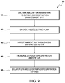
- FIG. 9 is a flowchart showing methods according to aspects of the present disclosure.
- the present disclosure is directed to apparatuses, systems, and methods for producing and delivering to a user air having an oxygen concentration that is higher than the ambient oxygen concentration in ambient air in an environment.
- the apparatuses, systems, and methods disclosed herein include at least one piezoelectric pump operable to direct ambient air through at least one gas separation filter, and then direct the oxygen-enriched air to a user, proximate to a user, or to a zone inhabited by a user.
- at least one piezoelectric pump is configured to also direct ambient air at a positive pressure to apparatuses and systems (e.g., apparatuses and systems comprising the gas separation filter(s)) disclosed herein.
- FIG. 1 is a representative view of an oxygen concentration enhancement system 10 according to an aspect of the present disclosure.
- an oxygen separation unit 12 (referred to herein as unit 12 ) includes an inlet 12 a , with unit 12 further being in communication with a power source (shown in FIG. 7 ) via a power cord 14 having a plug 15 (with plug 15 shown in FIG. 1 in non-limiting fashion as a Universal Serial Bus (USB) port plug) suitable for engagement with a power source (not shown in FIG. 1 , but represented in non-limiting fashion in FIG. 7 as feature 68 ).
- Unit 12 includes an outlet 12 b in communication with a tube 16 that is configured to direct an oxygen-enhanced airflow from unit 12 to enhanced oxygen directing device 19 .
- enhanced oxygen directing device 19 is configured in non-limiting fashion as a headset to fit onto the head 18 of a user 17 .
- Enhanced oxygen directing device 19 comprises an enhanced oxygen directing device outlet 19 a , configured to direct an oxygen enhanced airflow to the head 18 of user 17 .
- the power cord plug 15 may be any plug type that facilitates a connection of the oxygen concentration enhancement unit 12 to a power source (not shown in FIG.
- DC direct current
- the enhanced oxygen directing device 19 is shown in FIG. 1 to be a headset, aspects of the present disclosure further contemplate any device that can direct, re-direct, concentrate, or otherwise impact the direction and/or rate of an airflow having an enhanced oxygen concentration to the immediate vicinity of user, referred to herein as a zone inhabited by a user. That is, according to aspects of the present disclosure, the headset configuration for the enhanced oxygen directing device 19 , as shown in FIG. 1 , releases and directs an airflow containing an enhanced oxygen concentration proximate to oral and nasal cavities of a user to facilitate inhalation of air having an enhanced oxygen concentration as compared to the oxygen concentration of ambient air.
- enhanced oxygen directing devices are contemplated where airflow is released (e.g., at a positive pressure) to an inhalation area or “zone” inhabited by users that can be more indirect and potentially less cumbersome than a headset.
- the present disclosure further contemplates an enhanced oxygen concentration directing device emanating directly from unit 12 , and/or that can be manipulated to direct an outflow of oxygen in any desired direction.
- the directing device may be contained within the unit, such that the unit itself can be positioned proximate to a user (e.g., held by a user in a position such that an oxygen enriched airflow emitted by the unit itself can be inhaled by the user).
- FIG. 2 is an enlarged perspective view of the unit 12 shown in FIG. 1 . While shown as being cylindrical in shape, unit 12 can be of any shape, or housed in a housing 22 of any desirable shape (e.g., circular, rectangular, etc.). Unit 12 , as shown in FIG. 2 , includes an inlet end 12 a and an outlet end 12 b , with outlet stem 26 passing through end seal 24 . The presence of a connector such as the outlet stem 26 can be obviated making the stem 26 optional, so long as the outlet of the unit is in communication with a means for directing (e.g. the tube 16 shown in FIG. 1 ) a treated airflow having an enhanced oxygen concentration away from the unit and to a device for directing the treated airflow to a user or a zone inhabited by a user.
- a means for directing e.g. the tube 16 shown in FIG. 1
- a treated airflow having an enhanced oxygen concentration away from the unit and to a device for directing the treated airflow to a user or
- gas separation filters located within unit 12 separate and isolate components of the admitted ambient air, with the result being an increased concentration of oxygen (as compared to the oxygen concentration present in the ambient air introduced to the unit 12 ) in the air that is released from and otherwise directed from unit 12 as outflow via an outflow pathway 28 bounded by stem 26 .
- ambient air is directed into the unit 12 , for example, by any suitable means for directing air at a positive pressure (e.g., pump, blower, etc.).
- a positive pressure e.g., pump, blower, etc.
- Such means for directing air into or out of the unit 12 can be positioned within or proximate to the unit 12 .
- Positive pressure refers to an air pressure value that is greater than ambient air pressure. Ambient air pressure at sea level has an accepted value of 14.7 psi. In operation, a pressure gradient is formed to facilitate entry of ambient air into the unit 12 .
- a negative pressure e.g., a vacuum
- present aspects of this disclosure contemplate the positive pressure created via the process of ambient air introduction into unit 12 exclusively or in part due to the action of one or more piezoelectric pumps located within unit 12 .
- FIG. 3 is a schematic diagram according to aspects of the present disclosure showing a cross-sectional perspective view of the oxygen concentration enhancement system 30 that can be incorporated into the oxygen concentration enhancement system 10 shown in FIG. 1 , and further incorporating the oxygen concentration enhancement unit 12 shown in FIGS. 1 and 2 .
- unit 12 is in communication with blower 31 that is further in communication with an ambient air delivery line 32 that is, in turn, in communication with a plurality of piezoelectric pumps also referred to equivalently as piezoelectric drive pumps, and piezoelectric diaphragm pumps, with the understanding that a piezoelectric drive works in concert with, and drives, a pump mechanism (hereinafter “pumps”) 34 a , 34 b and 34 c .
- a pump mechanism hereinafter “pumps”) 34 a , 34 b and 34 c .
- the pumps include a corresponding pump inlet line 33 a , 33 b and 33 c .
- Each of the pumps 34 a , 34 b , 34 c and 34 d shown in FIG. 3 are positioned proximate to gas separation filters 35 a , 35 b and 35 c respectively (hereinafter “filters”).
- the plurality of gas separation filters can be equivalently referred to as gas separation membranes. Examples of the piezoelectric pumps, or drives used to power the pumps as well as examples of gas separation filters are described in greater detail below.
- ambient air is introduced to the system 30 via the blower 31 .
- the blower 31 can include positive pressure blowers or other devices (not shown) for the purpose of creating a pressure gradient that directs ambient air into the system 30 .
- the positive pressure generator 31 that can be in the form of a blower (hereinafter “blower” 31 ) is but one example of a presently contemplated positive pressure generator able to direct ambient air into the system 30 .
- Ambient air has an ambient oxygen concentration.
- Ambient oxygen concentration refers to an amount of oxygen in the ambient air as compared to the amount of other gases present in the ambient air.
- the average composition of ambient air at sea level comprises comparative concentrations of about 78 mol fraction % nitrogen, and about 21 mol fraction % oxygen, with the remaining 1 mol fraction % comprising mostly argon and carbon dioxide.
- the presently disclosed apparatuses, systems, and methods increase, or “enhance” the oxygen concentration in ambient air by about 28% to an oxygen enriched concentration in the treated air of about 26.88 mol fraction %.
- a user located at, or proximate to, such point of release that inhales such oxygen enhanced air will be inhaling air having an oxygen concentration that is enhanced by up to about 28% as compared to the ambient oxygen concentration in the ambient air otherwise present for breathing.
- each gas separation filter treats an amount of ambient air introduced to the system 30 “in parallel” to increase the oxygen concentration initially present in the ambient air (e.g., the ambient oxygen concentration of the ambient air introduced to the system 30 ). That is, an amount of ambient air having an ambient oxygen concentration is directed from the ambient air delivery line into the system 30 , into unit 12 , and directed to one of a plurality of piezoelectric pumps 34 a , 34 b , or 34 c . via the ambient air delivery line 32 . As shown in FIG. 3 , each of the piezoelectric pumps comprises or is otherwise driven by a piezoelectric pump drive. The pumps are engaged to an operating mode and air is directed by the action of the piezoelectric pumps into and through the gas separation filters 35 a , 35 b , 35 c , and delivered from the system via the enhanced oxygen directing device 19 .
- air having an enhanced oxygen concentration leaves each filter 35 a , 35 b and 35 c respectively through gas separation filter outlet lines 36 b , 36 c , and 36 d .
- the gas separation filter outlet lines 36 b , 36 c , and 36 d are in communication with (and direct the air having an enhanced concentration to) an enhanced oxygen concentration airflow line 38 .
- the air leaving the outlet lines, and that is combined in the enhanced concentration airflow line 38 has an enhanced oxygen concentration as compared to the ambient oxygen concentration in the ambient air.
- the filters in unit 12 are said to be arranged “in parallel”. That is, the oxygen concentration value of the air leaving each gas separation filter is substantially equivalent relative to one another.
- the ambient air As the ambient air enters the system 30 it is directed into the ambient air delivery line 32 that then branches off as needed along the unit 12 to introduce ambient air from the ambient air delivery line 32 respectively to a piezoelectric pumps 34 a , 34 b , 34 c via gas separation filter inlets 33 a , 33 b and 33 c .
- the piezoelectric pumps 34 a , 34 b , and 34 c respectively direct air through system 12 and into gas separation filters 35 a , 35 b and 35 c .
- Treated air that now contains an enhanced oxygen concentration exits gas separation filters 35 a , 35 b , and 35 c respectively via gas separation outlet lines 36 b , 36 c , and 36 d .
- the gas separation outlet lines are each in communication with enhanced concentration airflow line 38 that is, in turn, in communication with the enhanced oxygen directing device 19 .
- Power for the oxygen concentration enhancement system 30 is directed from a power source (not shown in FIG. 3 ) to power a series of piezoelectric flow control valves.
- the valves controlling air input into a pump are labelled as “Vi”.
- Valves controlling air output from the pump into the filters and from the pump to gas separation filter outlet lines 36 b , 36 c , and 36 d are labelled as “Vo”.
- the valves are therefore positioned across piezoelectric diaphragm pump inlets and outlets throughout the oxygen concentration enhancement system 30 .
- the piezoelectric pumps and valves can be operably controlled and configured to at least control the rate and amount of: 1) air introduced into and directed out of the blower 31 by pump 34 a; 2) ambient air directed (e.g., pumped) into the system and into the first gas separation filter by pump 44 a; 3) the progressively enhanced oxygen concentrated air directed (e.g., pumped) into second and third gas separation filters by pumps 34 b , 34 c ; and 4) the enhanced oxygen concentrated air directed (e.g. pumped) out of the system 30 by pump 34 d and to the enhanced oxygen directing device 19 . While such valves and pumps shown for simplicity in FIG. 3 are located outside of the unit 12 , according to further aspects of the present disclosure, the piezoelectric pumps and valves can be dimensioned such that they are contained within a single unit housing as shown in FIGS. 1 and 2 .
- pumps 34 a , 34 b , 34 c , 34 d are powered and controlled to sustain alternating or pulsating phases or “strokes” (e.g., controlled suction and controlled compression strokes, etc.) to direct air through the unit 12 and system 30 .
- the air moving through the unit 12 generally follows the direction of the arrows shown in FIG. 3 .
- Unit 12 and system 30 can further comprise a number of pump inlet lines and/or outlet from unit 12 in excess of the number shown in FIG. 3 .
- any number of gas separation filters can be present in the unit 12 , and any number of units 12 can be present and incorporated into the oxygen concentration enhancement system 30 .
- aspects of the present disclosure further contemplate housing the entire system 30 within one or more housings.
- a blower or other means for directing ambient air into the system and the ambient air intake resides within a housing.
- an enhanced oxygen concentration airflow line and an enhanced oxygen directing device will also reside within a system's housing.
- the piezoelectric pumps in concert with the piezoelectric pump valves are responsible for directing airflow into, through and out of the unit 12 and across system 30 . That is, the piezoelectric pumps are configured to at least control the rate and amount of: 1) the ambient air introduced into the system 30 (e.g., by the blower 31 , etc.); 2) the amount and rate of ambient air pumped by pump 34 a from pump inlet line 33 a ; pump 34 b from pump inlet line 33 b ; pump 34 c from pump inlet line 33 c , etc.; 3) the amount and rate ambient air introduced and pumped into gas separation filters 35 a , 35 b and 35 c to form air having an enhanced oxygen concentration; and 4) the rate and amount of oxygen concentration enhanced air directed out of the gas separation filters and into the enhanced oxygen concentration airflow line 38 and to the enhanced oxygen directing device 19 and out of the system 30 .
- the air will engage a series of valves and pumps directing the ambient air into the gas separation filters for the purpose of enriching the oxygen concentration of the ambient air.
- Such oxygen concentration enhancement occurs, not by introducing any additional oxygen to the oxygen concentration enhancement system 30 , but by separating an amount of non-oxygen components from ambient air that is treated in the oxygen concentration enhancement system 30 .
- Such treatment of the ambient air in the gas separation filters forms an enhanced oxygen concentration in the airflow. This treatment results in an increase in the relative oxygen concentration in the air treated in the oxygen concentration enhancement system 30 (e.g., as compared to the oxygen concentration in the ambient air outside of the oxygen concentration enhancement system 30 ).
- the operation of the gas separation filters will be more fully discussed below.
- the gas separation filters may be one continuous gas separation device, or a series of thin and substantially flat or planar gas separation devices configured to be rolled onto itself, or themselves, and/or about a single axis. In this rolled configuration, the gas separation device, or devices would progressively treat the air introduced into the gas separation device(s) to progressively enhance and increase the oxygen concentration of the air progressing through the gas separation device(s), as non-oxygen components from the air are removed from the air in the gas separation device(s).
- ambient air having an ambient oxygen concentration is introduced into the unit 12 is directed to gas separation filter inlets 33 a , 33 b , and 33 c for treatment to remove an amount of non-oxygen-containing components in the ambient air, thus increasing or enhancing the oxygen concentration in the treated air.
- the air that has been treated and has had its oxygen concentration enhanced by the gas separation filters 35 a , 35 b , and 35 c is directed to gas separation filter outlets 36 b , 36 c , and 36 d .
- the outlets 36 b , 36 c and 36 d direct the enhanced oxygen concentration air flow to enhanced oxygen concentration air flow line 38 .
- the enhanced oxygen concentration air flow line 38 is in communication with the enhanced oxygen directing device 19 that is responsible for and configured to direct the air having an enhanced oxygen concentration to a user or zone inhabited by a user.
- FIG. 4 is a schematic diagram showing a cross-sectional perspective view of a “serial” oxygen concentration enhancement system 40 comprising an oxygen concentration enhancement unit 13 (hereinafter referred to as “unit 13 ”) that can be incorporated into the oxygen concentration enhancement systems shown in FIG. 1 , and that features oxygen concentration enhancement filters arranged “in series” as opposed to and in contrast with the parallel system shown in FIG. 3 . That is, an essential difference between unit 12 and unit 13 is the addition of manifolds or other connections in the unit 13 that direct an airflow containing air having a progressively enriched oxygen concentration through the system 40 from one gas separation filter to the next, (e.g., oxygen concentration is enriched “in series” rather than a parallel filter orientation as shown in FIG. 3 ).
- unit 13 oxygen concentration enhancement unit 13
- ambient air is directed to a first gas separation filter that treats the ambient air and increases the oxygen concentration of the ambient air.
- the “once-treated” air is directed from a first gas separation filter outlet to a second gas separation filter inlet of a second gas separation filter.
- the once-treated air is converted to “twice-treated air” in the second gas separation filter.
- the twice-treated air has a higher oxygen concentration than the first-treated air, and as the air is progressively treated, the air leaving each successive filter has a higher oxygen concentration.
- the process is continued progressively as into a third gas separation filter, although a different number of gas separation filters other than the three shown in FIG. 4 are also contemplated according to aspects of the present invention. Such a “series” orientation is described in detail below.
- unit 13 is in communication with blower 31 that is further in communication with an ambient air delivery line 42 that is in turn in communication with a piezoelectric pump (hereinafter “pump” or “pumps”) 44 a .
- pump a piezoelectric pump
- ambient air is introduced to the system 40 via the blower 31 .
- the blower 31 is but one example of a positive pressure generator able to create a pressure gradient, and the blower 31 can include or be replaced by any device able to create a pressure gradient that directs ambient air into, or facilitates the introduction of ambient air into the system 40 .
- the ambient air introduced to the system 40 has an ambient oxygen concentration.
- ambient oxygen concentration refers to an amount of oxygen in the ambient air as compared to amount of other gases present in the ambient air.
- the first gas separation filter 45 a treats an amount of ambient air introduced to the system 40 to form a “once-treated” amount of ambient air.
- Each successive gas separation filter 45 b , 45 c increases the oxygen concentration in the ambient air originally introduced into the system 40 to an oxygen concentration that is enhanced to a predetermined percentage beyond the percentage of oxygen present in the previous gas separation filter. That is, an amount of ambient air having an ambient oxygen concentration is directed from the ambient air delivery line 42 to a first gas separation filter 45 a to form an amount of “once-treated” air.
- the once-treated air is directed by pumps 44 b , 44 c from the first gas separation filter 45 a to the second gas separation filter 45 b via first manifold 46 a to form an amount of “twice-treated” air.
- the twice-treated air is then directed by pumps 44 d , 44 e from the second gas separation filter 45 b to the third gas separation filter 45 c via second manifold 46 b to form an amount of that has been treated three times.
- each gas separation filter As shown in FIG. 4 , air is driven through the gas separation filters sequentially by piezoelectric pump drives (e.g. “pumps”) associated with and in communication with each gas separation filter. That is, air having a progressively enhanced oxygen concentration leaves each filter 45 a , 45 b and 45 c .
- Gas separation filter partition seals 47 are shown positioned throughout unit 13 .
- the gas separation filter outlet line 46 c leaving the third gas separation filter 45 c directs the now three-times enhanced oxygen concentration air flow to the enhanced oxygen directing device 19 that is responsible for and configured to direct the air having an enhanced oxygen concentration to a user or zone inhabited by a user.
- the filters in unit 13 are said to be arranged “in series”. That is, the oxygen concentration value (e.g., oxygen percentage in the air) of the air leaving each filter is progressively increased by treatment in a subsequent gas separation filter.
- Power for the oxygen concentration enhancement system 40 is directed from a power source (not shown in FIG. 4 ) to power a series of piezoelectric flow control valves.
- the valves controlling air input into a pump is shown as valves labelled “Vi”.
- Valves controlling air output from the pump and into the sequential gas separation filters oriented in series 45 a , 45 b , 45 c and from the filters to the manifolds 46 a , 46 b and to the enhanced oxygen directing device 19 are shown as valves labelled “Vo”.
- the piezoelectric flow control valves Vo, Vi are therefore positioned across piezoelectric diaphragm pump inlets and outlets throughout the oxygen concentration enhancement system 30 , 40 .
- the piezoelectric drives including the pumps and valves are shown residing within a housing 41 . While the first and second manifolds 46 a , 46 b are shown extending beyond the boundary of the housing 41 , aspects of the present disclosure further contemplate such manifolds residing within the boundary of the housing 41 , such that the system 40 is contained within housing 41 , with the exception of the ambient air delivery line 42 and the enhanced oxygen concentration airflow line 48 and the enhanced oxygen directing device 19 that are shown to reside outside of the housing. Though not shown in FIG. 4 , aspects of the present disclosure further contemplate housing the entire system within one or more housings.
- a blower or other means for directing ambient air into the system and the ambient air intake resides within a housing.
- both an enhanced oxygen concentration airflow line and an enhanced oxygen directing device will also reside within a system's housing.
- the piezoelectric pumps 44 a , 44 b , 44 c , 44 d , 44 e , 44 f are operably synchronized or otherwise controlled in concert with one another and are responsible for directing airflow into, through and out of the unit 13 and across system 40 .
- the piezoelectric pumps and valves Vi, Vo can be operably controlled and configured to at least control the rate and amount of: 1) air introduced into and directed out of the blower 31 by pump 44 a; 2) ambient air directed (e.g., pumped) into the system and into the first gas separation filter by pump 44 a; 3) the progressively enhanced oxygen concentrated air directed (e.g., pumped) into second and third gas separation filters by pumps 44 b , 44 c , 44 d and 44 e ; and 4) the enhanced oxygen concentrated air directed (e.g. pumped) out of the system 40 by pump 44 f and to the enhanced oxygen directing device 19 and out of the system 40 .
- such oxygen concentration enhancement occurs, not by introducing any additional oxygen to the oxygen concentration enhancement system 40 , but by separating an amount of non-oxygen components from ambient air that is then treated in the oxygen concentration enhancement system 40 , resulting in an increase in the relative oxygen concentration in the air treated in the oxygen concentration enhancement system 40 as compared to the oxygen concentration in the ambient air outside of the oxygen concentration enhancement system 40 .
- the operation of the gas separation filters in system 40 will be more fully discussed below.
- pumps 44 a , 44 b , 44 c , 44 d , 44 e , and 44 f are powered and controlled to sustain alternating or pulsating phases or “strokes” (e.g., controlled suction and controlled compression strokes, etc.) to direct air through the unit 13 and system 40 .
- the air moving through the unit 13 generally follows the direction of the arrows shown in FIG. 4 .
- FIG. 4 further shows unit 13 and system 40 comprising a single pump inlet line and a single outlet to a directing device. While not shown in FIG. 4 , unit 13 and system 40 can further comprise a number of pump inlet lines and/or outlet from unit 13 in excess of the number shown in FIG. 4 .
- any number of gas separation filters can be present in the unit 13 , and any number of units 13 can be present and incorporated into the oxygen concentration enhancement system 40 .
- the gas separation filters present in system 40 can be one continuous gas separation device, or a series of thin and substantially flat or planar gas separation devices configured to be rolled onto itself, or themselves, and/or about a single axis. In this rolled configuration, the gas separation device, or devices would progressively treat the air introduced into the gas separation device(s) to progressively enhance and increase the oxygen concentration of the air progressing through the gas separation device(s), as non-oxygen components from the air are removed from the air in the gas separation device(s).
- ambient air having an ambient oxygen concentration is introduced into the unit 13 is progressively directed to a plurality of gas separation filters (e.g., in series) for treatment to remove an amount of non-oxygen-containing components in the ambient air, thus progressively increasing or enhancing the oxygen concentration in the treated air that is finally directed from the unit 13 and system 40 to an enhanced oxygen directing device 19 that is responsible for and configured to direct the air having an enhanced oxygen concentration to a user or to a zone or region inhabited by a user located proximate to the unit 13 .
- gas separation filters e.g., in series
- aspects of the present disclosure further contemplate that an enhanced oxygen concentration directing device emanating directly from unit 12 and 13 , and/or that can be manipulated to direct an outflow of oxygen in any desired direction.
- the directing device may be contained within the unit, such that the unit itself can be positioned proximate to a user (e.g., held by a user in a position such that an oxygen enriched airflow emitted by the unit itself can be inhaled by the user).
- FIG. 5 is a schematic diagram further outlining aspects of the present disclosure.
- an oxygen concentration enhancement system 50 comprises an oxygen concentration enhancement unit 51 (hereinafter “unit 51 ”) in communication with a power source 52 via a power cord 54 .
- the oxygen concentration enhancement unit 51 may be either system 30 or 40 shown in FIGS. 3 and 4 , respectively.
- System 50 can incorporate the systems and apparatuses outlined in FIGS. 1-4 .
- Ambient airflow “AA” is directed into the unit 51 in the direction of the arrow at an oxygen concentration enhancement unit intake 56 .
- the oxygen concentration is enhanced within the unit 51 according to mechanisms described above that take place within the unit 51 .
- the oxygen concentration enhancement unit outlet 58 is then directed from the oxygen concentration enhancement unit outlet 58 in the direction of the arrow to the immediate, or proximate vicinity of a user 55 , or to a zone inhabited by a user 55 .
- the user 55 inhabits a space in an aircraft passenger cabin 57 that is set within an aircraft 57 b .
- a passenger cabin air conditioner 59 conditions air from within the passenger cabin 57 or from an area 57 a between the passenger cabin 57 and an aircraft fuselage 57 a .
- the overall oxygen content in the aircraft passenger cabin 57 is not affected by the air having an enhanced oxygen concentration that is released by the unit 51 .
- oxygen already in an environment such as an aircraft
- has its concentration temporarily altered at isolated locations to allow a user to receive air having an enhanced oxygen concentration in the aspirated air that is consistent with or that exceeds oxygen concentrations experienced by a user on land, for example, at sea level.
- gas separation devices e.g. gas separation filters, etc.
- gas separation filters that can enhance oxygen concentration by: 1) separating oxygen; 2) separating nitrogen; and/or 3 ) separating both nitrogen and oxygen from ambient air
- FIG. 6 is a graph showing the comparative ratio of nitrogen to air in ambient air and showing that, as nitrogen is removed from ambient air (e.g., by a gas separation filter of the type disclosed herein, the overall oxygen concentration in the air treated and released by units comprising such gas separation filters will increase, thus enriching or enhancing the oxygen concentration of the ambient air initially introduced into the units. That is, the air released by the units of the present disclosure, to an immediate vicinity of a user will have a desired and predetermined enhanced oxygen concentration.
- the oxygen concentration enhancement units described herein can comprise a type of oxygen separation membrane technology that uses a spiral type gas separation membrane module where a flat film gas separation membrane is wound around, for example, a core tube. Air is preferably delivered to the separation membrane via a blower, or by creating a vacuum to induce a required airflow into the gas separation device.
- Useful gas separation devices include, without limitation, for example, gas separation cartridges manufactured by Ube Industries, Ltd., (Yamaguchi, Japan), although any gas separation device able to produce the desired oxygen concentration enhancement, and that can be used by achieving adequate pressure gradients via micro-pumps powered by piezoelectric devices are contemplated by the present disclosure.
- the systems and apparatuses of the present disclosure are thought to be particularly useful as personal devices that can be portable. Such presently contemplated devices and systems include those systems comprising component miniaturization, or at least comprising components scaled in size and dimension to facilitate assembly of a device and for personal use. Therefore the overall useful weight of an assembled oxygen concentration enhancement device according to further non-limiting aspects of the present disclosure can usefully range from about 0.5 pounds to about 5 pounds in weight, more preferably ranging from about 1 pound to about 3 pounds in weight.
- the portability of the systems and apparatuses according to aspects of the present disclosure further contemplate incorporating a desired number of suitable piezoelectric-driven pumps and valves as well as power and control systems that generate enough energy to operate and control the pumps and valves used to generate adequate airflow through the apparatuses and systems of the present disclosure.
- Such piezoelectric pumps include, without limitation, for example, diaphragm micro-pumps manufactured by TFS (Takasago Fluidic Systems—Westborough, Mass.); Servoflo (Lexington, Mass.); Such diaphragm micro-pumps driven by piezoelectric elements according to further non-limiting aspects of the present disclosure individually can achieve a standard oxygen flow rate ranging from about 10 to about 100 ml O 2 /min, and more preferably ranging from about 20 to about 40 ml O 2 /min. through a 1 mm thick membrane at ambient pressure and operating at ambient temperature.
- a plurality of micro-pumps and gas separation filters can also be oriented in series or in parallel as described above to achieve desired and predetermined flow rate ranges.
- the presently contemplated diaphragm micro-pumps driven by piezoelectric elements can further individually achieve a maximum pumping pressure ranging from about 26 kPa to about 45 kPa, or can be oriented in series or in parallel to achieve desired and predetermined pressure ranges.
- the overall dimension of such diaphragm micro-pumps driven by piezoelectric elements can range from about 25 ⁇ 25 ⁇ 4.8 mm to about 33 ⁇ 33 ⁇ 9 mm (length ⁇ width ⁇ height).
- Suitable piezoelectric drive pumps and controllers are further contemplated for use with the above-identified components.
- contemplated diaphragm micro-pumps can have drivers and controllers incorporated into the units and systems such that airflow rates and pressures can be preset, can be adjustable, or can be set by an external control signal that can be remotely generated.
- the drives contemplated for use in the present disclosure include those that can send or receive signals to a remote controller, including a wireless controller, that is in communication with, for example, an automated computer program, or that can be controlled in response to manual commands.
- aspects of the present disclosure further include various methods and processes implemented using various hardware configured in ways that can vary as desired.
- one or more processing functionality can be implemented using dedicated hardware, rather than a microprocessor configured with program instructions, depending on, e.g., the design and cost tradeoffs for the various approaches, and/or system-level requirements.
- the disclosed oxygen concentration enhancement devices and systems when constructed and dimensioned to be useful as personal and portable devices, self-containment into a single unit is contemplated.
- the contemplated oxygen concentration enhancement devices, units and systems can be powered with, for example, self-contained DC/battery power that is preferably rechargeable and can be integrated into the units, or powered by AC such that the unit can be engaged via suitable cord or wire to a power source.
- FIGS. 1-5 may be configured for use in an enclosed space, such as in a passenger aircraft.
- FIG. 7 shows an aircraft 60 .
- FIG. 8 is a cross-sectional view of aircraft 60 taken along line I-I in FIG. 7 .
- an aircraft fuselage 62 separates the exterior of the aircraft from an aircraft interior 64 .
- Seats 66 are shown with power sources 68 oriented beneath seats 66 and into which the systems and apparatuses of the present disclosure can be engaged to power such systems and apparatuses.
- FIG. 9 is flowchart outlining a contemplated method 80 comprising delivering an amount of ambient air 92 to an inlet of an oxygen concentration enhancement unit, with the oxygen concentration enhancement unit comprising at least one piezoelectric pump in communication with at least one gas separation filter and engaging 94 the piezoelectric pump.
- An amount of ambient air is directed 95 through the gas separation filter, and increasing 96 the ambient oxygen concentration in the ambient air introduced into the unit to form an amount of enhanced oxygen concentration airflow in the oxygen separation device, and delivering 98 air having an enhanced oxygen concentration as compared to the oxygen concentration in ambient air from the unit, for example, to a user.
- aspects of the present disclosure find use in a variety of potential applications, particularly in the transportation industry including, for example, aerospace, marine, automotive applications and other application where purified oxygen or air having an enhanced oxygen concentration exceeding the oxygen concentration in ambient air is desired.
- the oxygen is delivered at an enhanced concentration that is beyond the oxygen concentration found in ambient air also may be usefully employed in enclosed or partially enclosed spaces including, for example vehicles, including manned and unmanned aircraft, manned and unmanned spacecraft, manned and unmanned rotorcraft, manned and unmanned terrestrial vehicles, manned and unmanned surface water borne vehicles, manned and unmanned sub-surface water borne vehicles, satellites, etc.
Abstract
Description
Claims (20)
Priority Applications (1)
| Application Number | Priority Date | Filing Date | Title |
|---|---|---|---|
| US15/881,848 US10751665B2 (en) | 2018-01-29 | 2018-01-29 | Personal oxygen enhanced breathing system |
Applications Claiming Priority (1)
| Application Number | Priority Date | Filing Date | Title |
|---|---|---|---|
| US15/881,848 US10751665B2 (en) | 2018-01-29 | 2018-01-29 | Personal oxygen enhanced breathing system |
Publications (2)
| Publication Number | Publication Date |
|---|---|
| US20190232217A1 US20190232217A1 (en) | 2019-08-01 |
| US10751665B2 true US10751665B2 (en) | 2020-08-25 |
Family
ID=67391759
Family Applications (1)
| Application Number | Title | Priority Date | Filing Date |
|---|---|---|---|
| US15/881,848 Active 2038-07-30 US10751665B2 (en) | 2018-01-29 | 2018-01-29 | Personal oxygen enhanced breathing system |
Country Status (1)
| Country | Link |
|---|---|
| US (1) | US10751665B2 (en) |
Families Citing this family (1)
| Publication number | Priority date | Publication date | Assignee | Title |
|---|---|---|---|---|
| US11707592B2 (en) * | 2019-09-30 | 2023-07-25 | Worldwide Health Innovations, LLC | Device and method of generating an enriched gas within a nasal vestibule |
Citations (5)
| Publication number | Priority date | Publication date | Assignee | Title |
|---|---|---|---|---|
| US6165431A (en) | 1993-12-08 | 2000-12-26 | Eltron Research, Inc. | Methods for separating oxygen from oxygen-containing gases |
| US7682422B2 (en) | 2004-02-19 | 2010-03-23 | Ube Industries, Ltd. | Method for separating/recovering oxygen-rich air from air, its apparatus and gas separation membrane module |
| US20130233169A1 (en) * | 2012-03-09 | 2013-09-12 | William J. Daniels, JR. | System and method for concentrating gas |
| US8658089B2 (en) | 2005-08-04 | 2014-02-25 | Saban Ventures Pty Limited | Membrane concentrator |
| US20150367275A1 (en) * | 2013-01-30 | 2015-12-24 | Koninklijke Philips N.V. | Oxygen separation system and method of generating a flow of oxygen enriched gas |
-
2018
- 2018-01-29 US US15/881,848 patent/US10751665B2/en active Active
Patent Citations (5)
| Publication number | Priority date | Publication date | Assignee | Title |
|---|---|---|---|---|
| US6165431A (en) | 1993-12-08 | 2000-12-26 | Eltron Research, Inc. | Methods for separating oxygen from oxygen-containing gases |
| US7682422B2 (en) | 2004-02-19 | 2010-03-23 | Ube Industries, Ltd. | Method for separating/recovering oxygen-rich air from air, its apparatus and gas separation membrane module |
| US8658089B2 (en) | 2005-08-04 | 2014-02-25 | Saban Ventures Pty Limited | Membrane concentrator |
| US20130233169A1 (en) * | 2012-03-09 | 2013-09-12 | William J. Daniels, JR. | System and method for concentrating gas |
| US20150367275A1 (en) * | 2013-01-30 | 2015-12-24 | Koninklijke Philips N.V. | Oxygen separation system and method of generating a flow of oxygen enriched gas |
Non-Patent Citations (1)
| Title |
|---|
| Kerns, J. "Making Piezoelectronics Work for You," Machine Design, Mar. 1, 2016, Informa USA, Inc., pp. 36-41. |
Also Published As
| Publication number | Publication date |
|---|---|
| US20190232217A1 (en) | 2019-08-01 |
Similar Documents
| Publication | Publication Date | Title |
|---|---|---|
| US7694674B2 (en) | Oxygen generator with storage and conservation modes | |
| CN104540736A (en) | On-board generation of oxygen for aircraft passengers | |
| US8763712B2 (en) | Hypoxic aircraft fire prevention system with advanced hypoxic generator | |
| JP4396971B2 (en) | Life support system for aircraft | |
| US8141649B2 (en) | Hypoxic fire suppression system for aerospace applications | |
| EP2247340B1 (en) | Aircraft breathing system using obogs | |
| US20070062371A1 (en) | System and method for enriching aircraft cabin air with oxygen from a nitrogen generation system | |
| US10137275B2 (en) | Oxygen concentrator for high pressure oxygen delivery with oxygen circulation loop and improved portability | |
| US11628393B2 (en) | Vacuum assisted air separation module operation | |
| US4950315A (en) | Multiple head pumping | |
| US10751665B2 (en) | Personal oxygen enhanced breathing system | |
| EP0196157A1 (en) | Flueric partial pressure sensor | |
| JP4329998B2 (en) | Respiratory gas supply system | |
| CN101618246A (en) | Respirator system | |
| US20200246749A1 (en) | Air purifying system | |
| US7442238B2 (en) | Means for air fractionization | |
| JP2554832B2 (en) | Injection mechanism with filter for chemical and bacterial warfare | |
| US20180290757A1 (en) | Closed or semi-closed loop onboard ceramic oxygen generation system | |
| WO2021094323A1 (en) | Ventilation apparatus for aircraft | |
| RU2790084C1 (en) | Method for creating excess pressure in the under-mask space | |
| RU137785U1 (en) | PORTABLE OXYGEN MEMBRANE GENERATOR | |
| JP4243861B2 (en) | Air conditioner for aircraft | |
| RU2390357C1 (en) | Oxygen respiratory apparatus for hypoxia protection | |
| KR200302537Y1 (en) | oxygen supplier for automobile | |
| CN117284060A (en) | Method and system for regulating and controlling state of oxygen-enriched air in vehicle space, oxygen-enriched cabin and motor home |
Legal Events
| Date | Code | Title | Description |
|---|---|---|---|
| AS | Assignment |
Owner name: THE BOEING COMPANY, ILLINOIS Free format text: ASSIGNMENT OF ASSIGNORS INTEREST;ASSIGNOR:KIRKBRIDE, DAVID W;REEL/FRAME:044751/0685 Effective date: 20180126 |
|
| FEPP | Fee payment procedure |
Free format text: ENTITY STATUS SET TO UNDISCOUNTED (ORIGINAL EVENT CODE: BIG.); ENTITY STATUS OF PATENT OWNER: LARGE ENTITY |
|
| STPP | Information on status: patent application and granting procedure in general |
Free format text: NON FINAL ACTION MAILED |
|
| STPP | Information on status: patent application and granting procedure in general |
Free format text: NON FINAL ACTION MAILED |
|
| STPP | Information on status: patent application and granting procedure in general |
Free format text: RESPONSE TO NON-FINAL OFFICE ACTION ENTERED AND FORWARDED TO EXAMINER |
|
| STPP | Information on status: patent application and granting procedure in general |
Free format text: FINAL REJECTION MAILED |
|
| STPP | Information on status: patent application and granting procedure in general |
Free format text: NOTICE OF ALLOWANCE MAILED -- APPLICATION RECEIVED IN OFFICE OF PUBLICATIONS |
|
| STPP | Information on status: patent application and granting procedure in general |
Free format text: PUBLICATIONS -- ISSUE FEE PAYMENT VERIFIED |
|
| STCF | Information on status: patent grant |
Free format text: PATENTED CASE |
|
| MAFP | Maintenance fee payment |
Free format text: PAYMENT OF MAINTENANCE FEE, 4TH YEAR, LARGE ENTITY (ORIGINAL EVENT CODE: M1551); ENTITY STATUS OF PATENT OWNER: LARGE ENTITY Year of fee payment: 4 |