US10749401B2 - Rotor cap for electric generators - Google Patents
Rotor cap for electric generators Download PDFInfo
- Publication number
- US10749401B2 US10749401B2 US15/300,608 US201515300608A US10749401B2 US 10749401 B2 US10749401 B2 US 10749401B2 US 201515300608 A US201515300608 A US 201515300608A US 10749401 B2 US10749401 B2 US 10749401B2
- Authority
- US
- United States
- Prior art keywords
- rotor cap
- fiber
- reinforced plastic
- fibers
- rotor
- Prior art date
- Legal status (The legal status is an assumption and is not a legal conclusion. Google has not performed a legal analysis and makes no representation as to the accuracy of the status listed.)
- Active, expires
Links
- 239000012809 cooling fluid Substances 0.000 claims abstract description 46
- 229920002430 Fibre-reinforced plastic Polymers 0.000 claims abstract description 41
- 239000011151 fibre-reinforced plastic Substances 0.000 claims abstract description 41
- 239000000835 fiber Substances 0.000 claims description 45
- 238000009423 ventilation Methods 0.000 claims description 23
- 229910052751 metal Inorganic materials 0.000 claims description 15
- 239000002184 metal Substances 0.000 claims description 15
- 239000000919 ceramic Substances 0.000 claims description 8
- 239000011159 matrix material Substances 0.000 claims description 7
- 125000006850 spacer group Chemical group 0.000 claims description 7
- 229920000049 Carbon (fiber) Polymers 0.000 claims description 6
- 239000004917 carbon fiber Substances 0.000 claims description 6
- 229920005989 resin Polymers 0.000 claims description 4
- 239000011347 resin Substances 0.000 claims description 4
- ZOXJGFHDIHLPTG-UHFFFAOYSA-N Boron Chemical compound [B] ZOXJGFHDIHLPTG-UHFFFAOYSA-N 0.000 claims description 3
- 229910052796 boron Inorganic materials 0.000 claims description 3
- TWNQGVIAIRXVLR-UHFFFAOYSA-N oxo(oxoalumanyloxy)alumane Chemical compound O=[Al]O[Al]=O TWNQGVIAIRXVLR-UHFFFAOYSA-N 0.000 claims description 3
- 238000004519 manufacturing process Methods 0.000 abstract description 13
- 239000000463 material Substances 0.000 abstract description 5
- 238000001816 cooling Methods 0.000 description 22
- 238000004804 winding Methods 0.000 description 18
- 238000013461 design Methods 0.000 description 13
- 239000012530 fluid Substances 0.000 description 11
- 239000004918 carbon fiber reinforced polymer Substances 0.000 description 8
- 239000002131 composite material Substances 0.000 description 7
- 229920003023 plastic Polymers 0.000 description 6
- 239000004033 plastic Substances 0.000 description 6
- 229910000831 Steel Inorganic materials 0.000 description 5
- 239000007789 gas Substances 0.000 description 5
- 239000010959 steel Substances 0.000 description 5
- BQCADISMDOOEFD-UHFFFAOYSA-N Silver Chemical compound [Ag] BQCADISMDOOEFD-UHFFFAOYSA-N 0.000 description 4
- 238000011161 development Methods 0.000 description 4
- 239000003822 epoxy resin Substances 0.000 description 4
- 238000003475 lamination Methods 0.000 description 4
- 229920000647 polyepoxide Polymers 0.000 description 4
- 229910052709 silver Inorganic materials 0.000 description 4
- 239000004332 silver Substances 0.000 description 4
- UFHFLCQGNIYNRP-UHFFFAOYSA-N Hydrogen Chemical compound [H][H] UFHFLCQGNIYNRP-UHFFFAOYSA-N 0.000 description 3
- 238000010438 heat treatment Methods 0.000 description 3
- 229910052739 hydrogen Inorganic materials 0.000 description 3
- 239000001257 hydrogen Substances 0.000 description 3
- 238000001228 spectrum Methods 0.000 description 3
- RYGMFSIKBFXOCR-UHFFFAOYSA-N Copper Chemical compound [Cu] RYGMFSIKBFXOCR-UHFFFAOYSA-N 0.000 description 2
- VYPSYNLAJGMNEJ-UHFFFAOYSA-N Silicium dioxide Chemical compound O=[Si]=O VYPSYNLAJGMNEJ-UHFFFAOYSA-N 0.000 description 2
- 239000000956 alloy Substances 0.000 description 2
- 229910045601 alloy Inorganic materials 0.000 description 2
- 239000004760 aramid Substances 0.000 description 2
- 229920006231 aramid fiber Polymers 0.000 description 2
- 239000004020 conductor Substances 0.000 description 2
- 239000002826 coolant Substances 0.000 description 2
- 229910052802 copper Inorganic materials 0.000 description 2
- 239000010949 copper Substances 0.000 description 2
- 230000005611 electricity Effects 0.000 description 2
- 229920002239 polyacrylonitrile Polymers 0.000 description 2
- 230000000284 resting effect Effects 0.000 description 2
- 229910052582 BN Inorganic materials 0.000 description 1
- PZNSFCLAULLKQX-UHFFFAOYSA-N Boron nitride Chemical compound N#B PZNSFCLAULLKQX-UHFFFAOYSA-N 0.000 description 1
- OKTJSMMVPCPJKN-UHFFFAOYSA-N Carbon Chemical compound [C] OKTJSMMVPCPJKN-UHFFFAOYSA-N 0.000 description 1
- 102100040287 GTP cyclohydrolase 1 feedback regulatory protein Human genes 0.000 description 1
- 101710185324 GTP cyclohydrolase 1 feedback regulatory protein Proteins 0.000 description 1
- 238000010521 absorption reaction Methods 0.000 description 1
- 239000002253 acid Substances 0.000 description 1
- 150000007513 acids Chemical class 0.000 description 1
- 229910052782 aluminium Inorganic materials 0.000 description 1
- XAGFODPZIPBFFR-UHFFFAOYSA-N aluminium Chemical compound [Al] XAGFODPZIPBFFR-UHFFFAOYSA-N 0.000 description 1
- 238000013459 approach Methods 0.000 description 1
- 230000015572 biosynthetic process Effects 0.000 description 1
- 229910052810 boron oxide Inorganic materials 0.000 description 1
- 235000019577 caloric intake Nutrition 0.000 description 1
- 239000011248 coating agent Substances 0.000 description 1
- 238000000576 coating method Methods 0.000 description 1
- 230000006835 compression Effects 0.000 description 1
- 238000007906 compression Methods 0.000 description 1
- 238000010276 construction Methods 0.000 description 1
- 230000006378 damage Effects 0.000 description 1
- 238000013016 damping Methods 0.000 description 1
- 239000012799 electrically-conductive coating Substances 0.000 description 1
- 238000005516 engineering process Methods 0.000 description 1
- 239000004744 fabric Substances 0.000 description 1
- 238000009730 filament winding Methods 0.000 description 1
- 230000009970 fire resistant effect Effects 0.000 description 1
- 229910002804 graphite Inorganic materials 0.000 description 1
- 239000010439 graphite Substances 0.000 description 1
- 238000003780 insertion Methods 0.000 description 1
- 230000037431 insertion Effects 0.000 description 1
- 150000002736 metal compounds Chemical class 0.000 description 1
- 239000002923 metal particle Substances 0.000 description 1
- 238000000034 method Methods 0.000 description 1
- 238000003801 milling Methods 0.000 description 1
- -1 nitrides Chemical class 0.000 description 1
- 150000004767 nitrides Chemical class 0.000 description 1
- 230000010355 oscillation Effects 0.000 description 1
- 239000002245 particle Substances 0.000 description 1
- 229920000642 polymer Polymers 0.000 description 1
- 230000035939 shock Effects 0.000 description 1
- HBMJWWWQQXIZIP-UHFFFAOYSA-N silicon carbide Chemical compound [Si+]#[C-] HBMJWWWQQXIZIP-UHFFFAOYSA-N 0.000 description 1
- 229910010271 silicon carbide Inorganic materials 0.000 description 1
- 239000000377 silicon dioxide Substances 0.000 description 1
- 235000012239 silicon dioxide Nutrition 0.000 description 1
- 239000007787 solid Substances 0.000 description 1
- 239000000126 substance Substances 0.000 description 1
- 229920001187 thermosetting polymer Polymers 0.000 description 1
- 238000001721 transfer moulding Methods 0.000 description 1
- 239000002759 woven fabric Substances 0.000 description 1
Images


Classifications
-
- H—ELECTRICITY
- H02—GENERATION; CONVERSION OR DISTRIBUTION OF ELECTRIC POWER
- H02K—DYNAMO-ELECTRIC MACHINES
- H02K3/00—Details of windings
- H02K3/46—Fastening of windings on the stator or rotor structure
- H02K3/50—Fastening of winding heads, equalising connectors, or connections thereto
- H02K3/51—Fastening of winding heads, equalising connectors, or connections thereto applicable to rotors only
-
- H—ELECTRICITY
- H02—GENERATION; CONVERSION OR DISTRIBUTION OF ELECTRIC POWER
- H02K—DYNAMO-ELECTRIC MACHINES
- H02K15/00—Methods or apparatus specially adapted for manufacturing, assembling, maintaining or repairing of dynamo-electric machines
- H02K15/0025—Shaping or compacting conductors or winding heads after the installation of the winding in the core or machine ; Applying fastening means on winding heads
- H02K15/0037—Shaping or compacting winding heads
-
- H—ELECTRICITY
- H02—GENERATION; CONVERSION OR DISTRIBUTION OF ELECTRIC POWER
- H02K—DYNAMO-ELECTRIC MACHINES
- H02K5/00—Casings; Enclosures; Supports
- H02K5/02—Casings or enclosures characterised by the material thereof
-
- H—ELECTRICITY
- H02—GENERATION; CONVERSION OR DISTRIBUTION OF ELECTRIC POWER
- H02K—DYNAMO-ELECTRIC MACHINES
- H02K5/00—Casings; Enclosures; Supports
- H02K5/04—Casings or enclosures characterised by the shape, form or construction thereof
- H02K5/20—Casings or enclosures characterised by the shape, form or construction thereof with channels or ducts for flow of cooling medium
- H02K5/207—Casings or enclosures characterised by the shape, form or construction thereof with channels or ducts for flow of cooling medium with openings in the casing specially adapted for ambient air
-
- H—ELECTRICITY
- H02—GENERATION; CONVERSION OR DISTRIBUTION OF ELECTRIC POWER
- H02K—DYNAMO-ELECTRIC MACHINES
- H02K7/00—Arrangements for handling mechanical energy structurally associated with dynamo-electric machines, e.g. structural association with mechanical driving motors or auxiliary dynamo-electric machines
- H02K7/18—Structural association of electric generators with mechanical driving motors, e.g. with turbines
- H02K7/1807—Rotary generators
- H02K7/1823—Rotary generators structurally associated with turbines or similar engines
Definitions
- the invention relates to a rotor cap for an electric generator, and to a production method therefor.
- the invention furthermore relates to such a generator.
- the invention is in particular advantageously applicable in high speed turbogenerators.
- the rotor cap in contrast to the rotor itself, is generally made of a high-alloyed non-magnetizable steel and, together with the slot wedges at the surface of the rotor, forms an electrically conductive cage which is known as the damper winding.
- the damper winding serves to reduce shock loads (pole wheel oscillations) and the heating of the rotor in the case of a load imbalance. In the case of symmetrical load, no alternating fields and thus also no eddy currents occur in the rotor, which is forged from solid steel.
- a magnetic rotating field occurs in the steel core of the rotor, and this can result in eddy currents and in impermissible heating and, in extreme cases, in the destruction of the turbogenerator. This needs to be ruled out for the projected service life.
- These functions are taken on by the rotor caps. They are the most highly loaded components of the turbogenerator. The rotor caps are in most cases shrunk in an overhung manner onto the body ends and are secured against rotational and axial movements by a kind of bayonet connection, for example. On the side remote from the bodies, a support ring is in many cases shrunk into the rotor cap, said support ring absorbing the forces of the end windings that act in the longitudinal direction.
- the cooling fluid is conducted in ducts from the main fan to the cooler. From there, the cooling medium flows without heating up as a result of fan losses and compression to the machine parts to be cooled, in particular also to the rotor coils.
- axial fans are generally used for cost reasons both in pressure ventilation and in suction ventilation in the case of air cooling.
- radial fans and multistage axial fans are also used.
- the rotor caps have generally been produced from metal or an alloy.
- EP 1628382 B1 discloses a structure in which the rotor caps or cap rings (both of these terms are used synonymously in the present document) are made of alloyed metal. Although optimum mechanical properties are realized in this case, both production times and production costs are very high and there is no design for cooling.
- One embodiment provides a rotor cap for an electric generator, wherein the rotor cap consists at least partially of fiber-reinforced plastic into which cooling fluid passages are incorporated.
- the fibers have at least one preferred direction which comprises in particular at least substantially a circumferential direction of the rotor cap.
- the fibers comprise carbon fibers.
- the fibers comprise ceramic fibers, in particular aluminum oxide fibers.
- the fibers comprise boron fibers.
- the fibers are embedded in a matrix of resin, in particular epoxy resin.
- cooling fluid passages are gas passages.
- cooling fluid passages are holes or slots.
- edges of the cooling fluid passages are formed in a fluidic manner.
- Another embodiment provides a method for producing a rotor cap by lamination, wherein, during the lamination of the fiber composite plastic, the cooling fluid passages are formed in an axial direction by the use of inserts, e.g., cylindrical inserts.
- Another embodiment provides an electric generator, e.g., a turbogenerator, having at least one rotor cap, wherein the at least one rotor cap is a rotor cap as disclosed above.
- FIG. 1 shows a table which lists turbogenerators, sorted in accordance with output spectrum, and specifies the cooling systems that are predominantly used therein.
- FIG. 2 shows a conventional generator cooling system.
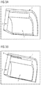
- FIG. 3A shows a conventional rotor cap made of metal.
- FIG. 3B shows a rotor cap at least partially made of fiber-reinforced plastic, according to one embodiment.
- FIGS. 4A-4C show example embodiments of cooling fluid passages, e.g., in the fiber-reinforced plastic of a rotor cap.
- FIG. 4A shows a first embodiment with ventilation holes that serve as a cooling fluid passage
- FIG. 4B shows a second embodiment with ventilation slots that extend obliquely to a main load direction
- FIG. 4C shows a third embodiment with ventilation slots that extend along a main load direction.
- FIGS. 5A-5E show example designs of the edges of cooling fluid passages a rotor cap.
- FIG. 5A shows a conventional simple edge design
- FIG. 5B shows an edge design with humped profiles
- FIG. 5 c shows an edge design with humped profiles with a golf ball dimple at the inlet
- FIG. 5D shows an edge design with a golf ball profile
- FIG. 5E shows an example embodiment of the cooling fluid passages with beveled edges.
- FIG. 6 shows an example generator cooling system, which may provide fluid flows via a rotor cap, according to one embodiment.
- Embodiments of the present invention provide a rotor cap for an electric generator, by way of which the disadvantages of the prior art, in particular in the area of cooling the rotor end winding, are at least partially overcome.
- a general finding of the invention is that the production of rotor caps from metal and/or alloyed metal with maximum mechanical properties is possible only in a closed form.
- the closed embodiment of the rotor caps on both sides of the rotor brings about a considerable limitation with regard to the cooling of the internal conductors in particular in the region of the end winding (cf. in this regard FIGS. 2 and 6 ).
- Effective cooling with cooling fluid such as air or hydrogen would ideally take place in the axial direction, said cooling fluid flowing in on one side in the form of a cold fluid flow and being discharged on the opposite side.
- This effective cooling may be achieved by embodiments of the invention by a rotor cap which is made at least partially of fiber-reinforced plastic and has, at least to some extent, cooling fluid passages in the region of the fiber reinforced plastic.
- FIG. 1 shows a table which lists the output spectrum of current turbogenerators.
- FIG. 1 shows a table which lists turbogenerators, sorted in accordance with output spectrum, and specifies the cooling systems that are predominantly used therein. Some embodiments may be suitable, e.g., for generators having—at least according to this list—air- and/or hydrogen-cooled rotors up to an output of about 1400 MVA.
- FIG. 2 shows the preferred cooling concept of such generators, wherein the rotor caps 1 and the hydrogen-cooled rotor 2 .
- FIG. 2 reproduces the prior art and FIG. 6 the improvement thereto provided by an embodiment of the invention.
- FIG. 6 shows the same view as FIG. 2 , wherein the fluid flows which are possible by the use of a rotor cap according to an embodiment of the invention in the region of the rotor cap are shown in FIG. 6 .
- FIG. 2 clearly illustrates, by way of the arrows 3 , good axial cooling by introduction of cold fluid, which flows into the system, initially in the cold state, from the fluid passages 2 , axially cools the rotor 2 in the process and leaves the system again as a heated and used fluid flow 4 .
- the fluid flows 3 turn into heated fluid flows 4 by energy intake and are removed from the system again.
- FIG. 6 shows the same view according to an embodiment of the invention, with the expanded flows, brought about by the use of rotor caps according to an embodiment of the invention, in the region 1 of the rotor caps.
- FIG. 3 shows a conventional rotor cap made of metal compared with a rotor cap made of fiber-reinforced plastic.
- FIG. 3 shows an oblique view of a part of a rotor cap 1 of a turbogenerator in a quarter sector section about a longitudinal axis in the region of the rotor cap 1 .
- the rotor cap 1 is mounted on a rotor end 2 in the region of its end side and laterally surrounds a rotor end winding 3 .
- FIG. 3 a shows in this case the prior art with a metal rotor cap 1 , which is produced for example from steel.
- the rotor end 2 and the rotor end winding 3 can also be seen.
- FIG. 3 b The same view can be seen in FIG. 3 b , but in this case a rotor cap 1 made of fiber-reinforced plastic, for example UD-CFRP, is shown.
- a rotor cap 1 made of fiber-reinforced plastic for example UD-CFRP.
- FIG. 3 b also shows, between the rotor cap 1 made of fiber-reinforced plastic and the rotor end winding 3 , or the rotor end 2 , the metal inlay, i.e. the spacer ring 4 .
- Some embodiments provide cooling in the region of the rotor cap in that the rotor cap consists at least partially of fiber-reinforced plastic and has ventilation slots, ventilation holes and/or other cooling fluid passages in the region of the fiber-reinforced plastic.
- a cooling fluid passage is in this case a ventilation opening in the rotor cap, in particular a gas passage, for example realized as a ventilation slot, as a ventilation hole, as an air and/or gas inlet and outlet, or simply as an opening or hole which passes through the fiber-reinforced plastic.
- a gas passage for example realized as a ventilation slot, as a ventilation hole, as an air and/or gas inlet and outlet, or simply as an opening or hole which passes through the fiber-reinforced plastic.
- any desired medium other than gas which is suitable at the location for heat absorption, can also be used as cooling fluid.
- the rotor cap is made entirely of fiber-reinforced plastic. It is particularly preferred here for the rotor cap to have ventilation slots and/or cooling fluid passages in each case in the main direction of load.
- the embodiment which comprises a spacer ring has been found to be particularly advantageous, and in this case in particular the variant in which this spacer ring is provided on its side resting against the fiber-reinforced plastic with a highly conductive layer, preferably made of silver.
- the fiber-reinforced plastic can also be referred to as a plastic matrix/fiber composite material.
- the fibers can be present or have been provided in particular as (loose) unidirectional fibers, as a woven fabric and/or as a laid fabric.
- the fibers comprise or are carbon fibers.
- Carbon fibers have the advantage that they allow high-strength matrix/fiber composite materials, are inexpensive, are widely available, are easy to handle in production and are also electrically conductive.
- the fibers comprise ceramic fibers.
- Ceramic fibers have the advantage of particularly high tensile strength and extensibility and also high-temperature resistance.
- the ceramic fibers can be in particular oxidic ceramic fibers, in particular aluminum oxide fibers or silicon dioxide fibers.
- the ceramic fibers can alternatively or in addition be nonoxidic ceramic fibers, in particular silicon carbide fibers.
- the fibers comprise boron fibers. These have extremely high strength and stiffness.
- the fibers comprise aramid fibers.
- Aramid fibers are distinguished by very high strength, high impact strength, high elongation at break, good vibration damping and high resistance to acids and alkalis. They are moreover extremely heat- and fire-resistant.
- the fibers are embedded in a plastic matrix of resin, in particular epoxy resin.
- Epoxy resin is well known as a matrix material for fibers and controllable. Epoxy resin also has a high strength and chemical resistance.
- other plastics, in particular thermosetting plastics, are also usable.
- the rotor cap is produced entirely from the fiber-reinforced plastic.
- the rotor cap has a spacer ring (“inlay”) intended as a bearing surface on its inner side.
- This can be produced from metal and/or be coated with a metal layer, in particular also with a silver layer.
- the spacer ring has, on its side resting against the fiber-reinforced plastic, a highly electrically conductive coating, in particular a silver coating.
- the fibers have at least one preferred direction.
- This preferred direction is then referred to for example as the main direction of load.
- ventilation slots, ventilation holes and/or other cooling fluid passages are arranged in the main direction of load.
- the at least one preferred direction comprises in particular at least substantially a circumferential direction of the rotor cap.
- a circumferential direction can be understood as meaning in particular a direction of a changing azimuth angle with regard to an axis of rotation or longitudinal axis of the rotor cap.
- FIG. 4 shows three exemplary embodiments of cooling fluid passages as are realized for example in the fiber-reinforced plastic of the rotor cap.
- FIG. 4 a shows, represented by the arrow 7 , the preferred direction within the fiber-reinforced plastic, and the ventilation holes 8 , which serve as the cooling fluid passage.
- FIG. 4 b again shows the preferred direction or main direction of load of the fiber-reinforced plastic and in addition the ventilation slots 9 which extend obliquely to the main direction of load.
- FIG. 4 c shows a further embodiment with ventilation slots 10 which extend in the main direction of load or preferred direction 7 of the fiber-reinforced plastic.
- cooling fluid passages are within the meaning of the present invention. They preferably lie in the radial direction, from the inside to the outside, in order to ensure fluid exchange, in particular gas exchange.
- the cooling fluid passages can in this case lead directly in the radial direction through the rotor cap or, to improve incident flow, obliquely through the thickness direction of the rotor cap.
- the cooling fluid passages can, in accordance with the variants specified in FIG. 5 , in addition to a simple variant, for example as illustrated in 5 a ) of FIG. 5 , also be designed in a flow-influencing manner or in some other way at the edges 11 of the cooling fluid passages.
- a number of types of the design of the edges 11 of the cooling fluid passages are illustrated by way of example in FIG. 5 .
- edges 11 can be formed differently or identically within a rotor cap and be combined in a uniform or different manner in subregions, depending on the embodiment.
- the outer and inner edges 11 of a cooling fluid passage 8 , 9 and/or 10 of the rotor cap 1 can in this case be formed identically or differently.
- opposing edges 11 of the outer or inner side of a cooling fluid passage can be different from one another or identical.
- FIG. 5 shows a few exemplary embodiments of the design of the edges 11 of the cooling fluid passages in rotor caps.
- FIG. 5 a shows the conventional very simple edge design.
- FIG. 5 b shows the design of the edges 11 with what are known as humped profiles.
- FIG. 5 c shows a development of the design of the edges 11 with what are known as humped profiles with a golf ball dimple at the inlet, and
- FIG. 5 d shows a design of the edges 11 with what is known as a golf ball profile.
- FIG. 5 e shows a further embodiment of the cooling fluid passages with beveled edges 11 .
- Said figure shows a structure similar to that of a grater with a cross-section e) which, upon axial incident flow, feeds the cooling fluid, for example the cold air, radially into the interior of the rotor cap with smooth redirection.
- the rotor cap can be produced by means of filament winding, by means of resin transfer molding (RTM) and/or by means of prepreg technology, for example.
- RTM resin transfer molding
- the polymeric fiber composite rotor cap can be finish-machined following production.
- the abovementioned geometries at cooling fluid passages can be introduced axially or radially into the rotor cap.
- the cooling fluid passages are formed by insertion of inserts, for example of cylindrical inserts, in the axial direction.
- inserts for example of cylindrical inserts
- These can consist of metal and of CFRP, GFRP or other plastics or composites.
- a spoke wheel is conceivable, which comprises an inner and an outer ring in which the fibers are located preferably in the circumferential direction. Introduced between these rings are CFRP struts or spokes which connect the two rings together in a torsion-resistant manner with respect to centrifugal and/or axial force.
- two CFRP rings are possible, which are realized with a gap in the cap circumference. This gap can be produced with axial “spokes” in order to connect the two rings.
- Suitable materials for producing the CFRP rotor cap are polyacrylonitrile (PAN)-based carbon fibers that are conventional for the structural-mechanical main body.
- PAN polyacrylonitrile
- high modulus fibers which are produced on the basis of pitch, can be used in part or entirely.
- a particle filling of the polymer matrix with graphite, short carbon fibers, aluminum-based, copper-based and/or silver-based metal particles and any desired alloys thereof and/or of thermally conductive metal compounds such as nitrides, for example boron nitride, or oxides is possible.
- the at least one preferred direction comprises precisely one preferred direction, i.e. the fibers are oriented unidirectionally at least locally. As a result, particularly high strength can be achieved in this preferred direction.
- FIG. 6 shows the improved cooling of a rotor end winding when use is made of the rotor caps according to one embodiment. Compared with FIG. 2 , it is clear here that further cooling fluid flows 6 pass through the rotor caps in order to cool the rotor end winding in the region 1 of the rotor caps.
- the invention relates to a rotor cap for an electric generator and to a production method therefor.
- the invention also relates to such a generator.
- the invention is applicable particularly advantageously in high speed turbo generators.
- the rotor cap ( 1 ) consists at least partially of fiber-reinforced plastic.
- the rotor cap ( 1 ) has cooling fluid passages, particularly preferably in the axial direction, i.e. outwardly from the inner side, adjoining the rotor end winding ( 3 ), of the rotor cap ( 1 ).
Abstract
Description
Claims (10)
Applications Claiming Priority (4)
| Application Number | Priority Date | Filing Date | Title |
|---|---|---|---|
| DE102014206010.9 | 2014-03-31 | ||
| DE102014206010 | 2014-03-31 | ||
| DE102014206010.9A DE102014206010A1 (en) | 2014-03-31 | 2014-03-31 | Rotor cap for electric generators |
| PCT/EP2015/055651 WO2015150077A1 (en) | 2014-03-31 | 2015-03-18 | Rotor cap for electric generators |
Publications (2)
| Publication Number | Publication Date |
|---|---|
| US20170110924A1 US20170110924A1 (en) | 2017-04-20 |
| US10749401B2 true US10749401B2 (en) | 2020-08-18 |
Family
ID=52785042
Family Applications (1)
| Application Number | Title | Priority Date | Filing Date |
|---|---|---|---|
| US15/300,608 Active 2037-01-31 US10749401B2 (en) | 2014-03-31 | 2015-03-18 | Rotor cap for electric generators |
Country Status (4)
| Country | Link |
|---|---|
| US (1) | US10749401B2 (en) |
| EP (1) | EP3058640B1 (en) |
| DE (1) | DE102014206010A1 (en) |
| WO (1) | WO2015150077A1 (en) |
Families Citing this family (3)
| Publication number | Priority date | Publication date | Assignee | Title |
|---|---|---|---|---|
| DE102014206010A1 (en) | 2014-03-31 | 2015-10-01 | Siemens Aktiengesellschaft | Rotor cap for electric generators |
| DE102018216586A1 (en) * | 2018-09-27 | 2020-04-02 | Siemens Aktiengesellschaft | Blocking element for rotor winding heads in turbogenerators with rotor cap with radial ventilation holes |
| CN110690782B (en) * | 2019-11-04 | 2021-10-26 | 安阳工学院 | Vibration-damping air-cooling woodworking electric spindle |
Citations (8)
| Publication number | Priority date | Publication date | Assignee | Title |
|---|---|---|---|---|
| DE19548321C1 (en) | 1995-12-22 | 1997-02-20 | Siemens Ag | Fan-wheel type cooling arrangement for electrical machines |
| DE19732949A1 (en) | 1997-07-31 | 1999-02-04 | Abb Research Ltd | Gas-cooled turbogenerator |
| US5928736A (en) | 1996-09-09 | 1999-07-27 | Raytheon Company | Composite structure having integrated aperture and method for its preparation |
| US20060038462A1 (en) | 2004-08-19 | 2006-02-23 | Alstom Technology Ltd. | Rotor for a generator, in particular a high-power turbogenerator |
| DE102010032827A1 (en) | 2010-05-11 | 2011-11-17 | Siemens Aktiengesellschaft | Runner with winding head cap |
| WO2012061856A2 (en) | 2010-11-10 | 2012-05-18 | Andritz Hydro Gmbh | Winding overhang support of a generator |
| DE102011077861A1 (en) | 2011-06-21 | 2012-12-27 | Siemens Aktiengesellschaft | Rotor cap for electric generators |
| WO2015150077A1 (en) | 2014-03-31 | 2015-10-08 | Siemens Aktiengesellschaft | Rotor cap for electric generators |
-
2014
- 2014-03-31 DE DE102014206010.9A patent/DE102014206010A1/en not_active Withdrawn
-
2015
- 2015-03-18 WO PCT/EP2015/055651 patent/WO2015150077A1/en active Application Filing
- 2015-03-18 EP EP15712564.2A patent/EP3058640B1/en active Active
- 2015-03-18 US US15/300,608 patent/US10749401B2/en active Active
Patent Citations (10)
| Publication number | Priority date | Publication date | Assignee | Title |
|---|---|---|---|---|
| DE19548321C1 (en) | 1995-12-22 | 1997-02-20 | Siemens Ag | Fan-wheel type cooling arrangement for electrical machines |
| US5928736A (en) | 1996-09-09 | 1999-07-27 | Raytheon Company | Composite structure having integrated aperture and method for its preparation |
| DE19732949A1 (en) | 1997-07-31 | 1999-02-04 | Abb Research Ltd | Gas-cooled turbogenerator |
| US20060038462A1 (en) | 2004-08-19 | 2006-02-23 | Alstom Technology Ltd. | Rotor for a generator, in particular a high-power turbogenerator |
| EP1628382B1 (en) | 2004-08-19 | 2007-11-28 | ALSTOM Technology Ltd | Rotor for a generator, in particular rotor for a high-power turbogenerator |
| DE102010032827A1 (en) | 2010-05-11 | 2011-11-17 | Siemens Aktiengesellschaft | Runner with winding head cap |
| WO2012061856A2 (en) | 2010-11-10 | 2012-05-18 | Andritz Hydro Gmbh | Winding overhang support of a generator |
| DE102011077861A1 (en) | 2011-06-21 | 2012-12-27 | Siemens Aktiengesellschaft | Rotor cap for electric generators |
| US20140125192A1 (en) | 2011-06-21 | 2014-05-08 | Peter Gröppel | Rotor end-bell for electric generators |
| WO2015150077A1 (en) | 2014-03-31 | 2015-10-08 | Siemens Aktiengesellschaft | Rotor cap for electric generators |
Non-Patent Citations (3)
| Title |
|---|
| European Office Action, Application No. 15712564.2, 5 pages, dated Dec. 20, 2018. |
| German Office Action, Application No. 102014206010.9, 8 pages, dated Mar. 16, 2015. |
| International Search Report and Written Opinion, Application No. PCT/EP2015/055651, 17 pages, dated Aug. 27, 2015. |
Also Published As
| Publication number | Publication date |
|---|---|
| DE102014206010A1 (en) | 2015-10-01 |
| EP3058640B1 (en) | 2020-07-22 |
| WO2015150077A1 (en) | 2015-10-08 |
| US20170110924A1 (en) | 2017-04-20 |
| EP3058640A1 (en) | 2016-08-24 |
Similar Documents
| Publication | Publication Date | Title |
|---|---|---|
| US10594190B2 (en) | Electrical machine rotors | |
| US8004140B2 (en) | Dovetail spoke internal permanent magnet machine | |
| US7098569B2 (en) | Rotor assembly for a permanent magnet power electric machine | |
| US9088190B2 (en) | Electrical machines and electrical machine rotors | |
| US7617582B2 (en) | Method of manufacturing composite generator rotor shaft | |
| US20050275304A1 (en) | Method and apparatus for reducing hot spot temperatures on stacked field windings | |
| US20120025654A1 (en) | Rotor of a permanent magnet synchronous machine | |
| US20130076169A1 (en) | Electrical machine with reduced windage loss | |
| US10749401B2 (en) | Rotor cap for electric generators | |
| EP3082224B1 (en) | System and method for supporting laminations of synchronous reluctance motors | |
| US7057326B2 (en) | Rotor body containment shell with reduced windage losses | |
| KR101870330B1 (en) | Rotor end-bell for electric generators | |
| US9812917B2 (en) | End turn support and cooling fixture | |
| US6957917B2 (en) | Hydrodynamic axial slide bearing for a generator | |
| JP2012523808A (en) | Dynamo Electric Machinery | |
| US20150128757A1 (en) | Flywheel | |
| CN109525048A (en) | Motor including being provided with the stator of inner tubular sleeve | |
| CN106357037A (en) | Motor rotor and motor | |
| JP6079083B2 (en) | Turbo molecular pumps and spacers | |
| EP2899850B1 (en) | Electric generator for a wind turbine with stator gaps varying in axial direction of the generator | |
| JP2011041460A (en) | Permanent magnet machine and rotor | |
| EP4024669A1 (en) | Outer rotor machine with banding sleeve | |
| JP2014239614A (en) | Motor structure | |
| JP2014134138A (en) | Turbo molecule pump |
Legal Events
| Date | Code | Title | Description |
|---|---|---|---|
| AS | Assignment |
Owner name: SIEMENS AKTIENGESELLSCHAFT, GERMANY Free format text: ASSIGNMENT OF ASSIGNORS INTEREST;ASSIGNORS:GROEPPEL, PETER;JOHANNES, MARTIN;ROHR, CLAUS;AND OTHERS;SIGNING DATES FROM 20160518 TO 20160615;REEL/FRAME:039898/0382 |
|
| STPP | Information on status: patent application and granting procedure in general |
Free format text: RESPONSE TO NON-FINAL OFFICE ACTION ENTERED AND FORWARDED TO EXAMINER |
|
| STPP | Information on status: patent application and granting procedure in general |
Free format text: NON FINAL ACTION MAILED |
|
| STPP | Information on status: patent application and granting procedure in general |
Free format text: RESPONSE TO NON-FINAL OFFICE ACTION ENTERED AND FORWARDED TO EXAMINER |
|
| STPP | Information on status: patent application and granting procedure in general |
Free format text: FINAL REJECTION MAILED |
|
| STPP | Information on status: patent application and granting procedure in general |
Free format text: NOTICE OF ALLOWANCE MAILED -- APPLICATION RECEIVED IN OFFICE OF PUBLICATIONS |
|
| STPP | Information on status: patent application and granting procedure in general |
Free format text: PUBLICATIONS -- ISSUE FEE PAYMENT VERIFIED |
|
| STCF | Information on status: patent grant |
Free format text: PATENTED CASE |
|
| AS | Assignment |
Owner name: SIEMENS ENERGY GLOBAL GMBH & CO. KG, GERMANY Free format text: ASSIGNMENT OF ASSIGNORS INTEREST;ASSIGNOR:SIEMENS AKTIENGESELLSCHAFT;REEL/FRAME:056501/0020 Effective date: 20210228 |
|
| FEPP | Fee payment procedure |
Free format text: MAINTENANCE FEE REMINDER MAILED (ORIGINAL EVENT CODE: REM.); ENTITY STATUS OF PATENT OWNER: LARGE ENTITY |