US10744803B2 - Tension controller, medium conveying device incorporating the tension controller, and image forming apparatus incorporating the medium conveying device - Google Patents
Tension controller, medium conveying device incorporating the tension controller, and image forming apparatus incorporating the medium conveying device Download PDFInfo
- Publication number
- US10744803B2 US10744803B2 US16/356,619 US201916356619A US10744803B2 US 10744803 B2 US10744803 B2 US 10744803B2 US 201916356619 A US201916356619 A US 201916356619A US 10744803 B2 US10744803 B2 US 10744803B2
- Authority
- US
- United States
- Prior art keywords
- shaft
- rotary shaft
- roll
- drive
- conveyance target
- Prior art date
- Legal status (The legal status is an assumption and is not a legal conclusion. Google has not performed a legal analysis and makes no representation as to the accuracy of the status listed.)
- Expired - Fee Related
Links
- 230000009467 reduction Effects 0.000 claims abstract description 24
- 230000005540 biological transmission Effects 0.000 claims abstract description 17
- 230000008859 change Effects 0.000 claims abstract description 11
- 238000001514 detection method Methods 0.000 claims description 15
- 238000011144 upstream manufacturing Methods 0.000 claims description 3
- 239000007788 liquid Substances 0.000 description 79
- 230000007246 mechanism Effects 0.000 description 44
- 239000000463 material Substances 0.000 description 19
- 238000007599 discharging Methods 0.000 description 8
- 239000000976 ink Substances 0.000 description 8
- 239000000243 solution Substances 0.000 description 6
- 238000012423 maintenance Methods 0.000 description 5
- 239000004744 fabric Substances 0.000 description 4
- 239000002994 raw material Substances 0.000 description 4
- 238000004519 manufacturing process Methods 0.000 description 3
- 239000004033 plastic Substances 0.000 description 3
- 239000000843 powder Substances 0.000 description 3
- 239000000853 adhesive Substances 0.000 description 2
- 230000001070 adhesive effect Effects 0.000 description 2
- 230000015572 biosynthetic process Effects 0.000 description 2
- 239000000919 ceramic Substances 0.000 description 2
- 238000010586 diagram Methods 0.000 description 2
- 239000000835 fiber Substances 0.000 description 2
- 239000010419 fine particle Substances 0.000 description 2
- 239000011521 glass Substances 0.000 description 2
- 239000008187 granular material Substances 0.000 description 2
- 230000003179 granulation Effects 0.000 description 2
- 238000005469 granulation Methods 0.000 description 2
- 238000002347 injection Methods 0.000 description 2
- 239000007924 injection Substances 0.000 description 2
- 239000010985 leather Substances 0.000 description 2
- 239000002184 metal Substances 0.000 description 2
- 229910052751 metal Inorganic materials 0.000 description 2
- 239000000203 mixture Substances 0.000 description 2
- 230000004048 modification Effects 0.000 description 2
- 238000012986 modification Methods 0.000 description 2
- 239000002023 wood Substances 0.000 description 2
- OYPRJOBELJOOCE-UHFFFAOYSA-N Calcium Chemical compound [Ca] OYPRJOBELJOOCE-UHFFFAOYSA-N 0.000 description 1
- BQCADISMDOOEFD-UHFFFAOYSA-N Silver Chemical compound [Ag] BQCADISMDOOEFD-UHFFFAOYSA-N 0.000 description 1
- 230000009471 action Effects 0.000 description 1
- 150000001413 amino acids Chemical class 0.000 description 1
- 239000011230 binding agent Substances 0.000 description 1
- 229910052791 calcium Inorganic materials 0.000 description 1
- 239000011575 calcium Substances 0.000 description 1
- 238000006243 chemical reaction Methods 0.000 description 1
- 239000011248 coating agent Substances 0.000 description 1
- 238000000576 coating method Methods 0.000 description 1
- 239000006185 dispersion Substances 0.000 description 1
- 239000003292 glue Substances 0.000 description 1
- 238000010438 heat treatment Methods 0.000 description 1
- 210000000056 organ Anatomy 0.000 description 1
- 230000002093 peripheral effect Effects 0.000 description 1
- 239000012466 permeate Substances 0.000 description 1
- 239000002985 plastic film Substances 0.000 description 1
- 229920006255 plastic film Polymers 0.000 description 1
- 102000004169 proteins and genes Human genes 0.000 description 1
- 108090000623 proteins and genes Proteins 0.000 description 1
- 238000005507 spraying Methods 0.000 description 1
- 239000000758 substrate Substances 0.000 description 1
Images


Classifications
-
- B—PERFORMING OPERATIONS; TRANSPORTING
- B41—PRINTING; LINING MACHINES; TYPEWRITERS; STAMPS
- B41J—TYPEWRITERS; SELECTIVE PRINTING MECHANISMS, i.e. MECHANISMS PRINTING OTHERWISE THAN FROM A FORME; CORRECTION OF TYPOGRAPHICAL ERRORS
- B41J15/00—Devices or arrangements of selective printing mechanisms, e.g. ink-jet printers or thermal printers, specially adapted for supporting or handling copy material in continuous form, e.g. webs
- B41J15/16—Means for tensioning or winding the web
-
- B—PERFORMING OPERATIONS; TRANSPORTING
- B41—PRINTING; LINING MACHINES; TYPEWRITERS; STAMPS
- B41J—TYPEWRITERS; SELECTIVE PRINTING MECHANISMS, i.e. MECHANISMS PRINTING OTHERWISE THAN FROM A FORME; CORRECTION OF TYPOGRAPHICAL ERRORS
- B41J11/00—Devices or arrangements of selective printing mechanisms, e.g. ink-jet printers or thermal printers, for supporting or handling copy material in sheet or web form
- B41J11/007—Conveyor belts or like feeding devices
-
- B—PERFORMING OPERATIONS; TRANSPORTING
- B65—CONVEYING; PACKING; STORING; HANDLING THIN OR FILAMENTARY MATERIAL
- B65H—HANDLING THIN OR FILAMENTARY MATERIAL, e.g. SHEETS, WEBS, CABLES
- B65H23/00—Registering, tensioning, smoothing or guiding webs
-
- B—PERFORMING OPERATIONS; TRANSPORTING
- B65—CONVEYING; PACKING; STORING; HANDLING THIN OR FILAMENTARY MATERIAL
- B65H—HANDLING THIN OR FILAMENTARY MATERIAL, e.g. SHEETS, WEBS, CABLES
- B65H23/00—Registering, tensioning, smoothing or guiding webs
- B65H23/04—Registering, tensioning, smoothing or guiding webs longitudinally
- B65H23/18—Registering, tensioning, smoothing or guiding webs longitudinally by controlling or regulating the web-advancing mechanism, e.g. mechanism acting on the running web
- B65H23/195—Registering, tensioning, smoothing or guiding webs longitudinally by controlling or regulating the web-advancing mechanism, e.g. mechanism acting on the running web in winding mechanisms or in connection with winding operations
-
- B—PERFORMING OPERATIONS; TRANSPORTING
- B65—CONVEYING; PACKING; STORING; HANDLING THIN OR FILAMENTARY MATERIAL
- B65H—HANDLING THIN OR FILAMENTARY MATERIAL, e.g. SHEETS, WEBS, CABLES
- B65H2403/00—Power transmission; Driving means
- B65H2403/70—Clutches; Couplings
- B65H2403/73—Couplings
- B65H2403/732—Torque limiters
-
- B—PERFORMING OPERATIONS; TRANSPORTING
- B65—CONVEYING; PACKING; STORING; HANDLING THIN OR FILAMENTARY MATERIAL
- B65H—HANDLING THIN OR FILAMENTARY MATERIAL, e.g. SHEETS, WEBS, CABLES
- B65H2403/00—Power transmission; Driving means
- B65H2403/80—Transmissions, i.e. for changing speed
- B65H2403/82—Variable speed drive units
- B65H2403/821—Variable speed drive units friction
-
- B—PERFORMING OPERATIONS; TRANSPORTING
- B65—CONVEYING; PACKING; STORING; HANDLING THIN OR FILAMENTARY MATERIAL
- B65H—HANDLING THIN OR FILAMENTARY MATERIAL, e.g. SHEETS, WEBS, CABLES
- B65H2801/00—Application field
- B65H2801/03—Image reproduction devices
- B65H2801/15—Digital printing machines
Definitions
- This disclosure relates to a tension controller, a medium conveying device incorporating the tension controller, and an image forming apparatus incorporating the medium conveying device.
- Various types of image forming apparatuses to which such a tension controller is applied are known to include a configuration in which a roll sheet (or a roll medium) that functions as a conveyance target medium is conveyed to a printing portion and an image is printed on the roll sheet.
- a tension applying device of a roller sheet feeding device has a configuration in which multiple friction torque panels are attached with friction to an interlocking shaft via a torque transmission panel.
- an electromagnetic clutch is turned on, a locking gear that meshes with a gear of each of the multiple friction torque panels is fixed to a locking shaft that is disposed parallel to a locking shaft.
- the electromagnetic clutch is turned off, the locking gear is rotated.
- At least one aspect of this disclosure provides a tension controller including a drive device and a drive transmission device.
- the drive device is configured to rotate a drive shaft.
- the drive transmission device configured to transmit a rotation driving force of the drive shaft of the drive device to rotate a rotary shaft of a roll of a conveyance target medium.
- the drive transmission device includes a tension applying device.
- the tension applying device includes a variable speed reducing device and a torque limiter.
- the variable speed reducing device and the torque limiter are disposed between the drive shaft of the drive device and the rotary shaft of the roll of the conveyance target medium.
- the variable speed reducing device of the tension applying device is configured to change a speed reduction ratio between the rotary shaft of the roll of the conveyance target medium and the torque limiter and to apply a tension force to the conveyance target medium.
- At least one aspect of this disclosure provides a medium conveying device including the above-described tension controller provided to at least one of a medium supplying device and a medium take-up device.
- the medium supplying device is disposed upstream from a sheet conveying device that conveys the conveyance target medium in a conveying direction and supplies the conveyance target medium.
- the medium take-up device is disposed downstream from the sheet conveying device in the conveying direction and take up the conveyance target medium.
- At least one aspect of this disclosure provides an image forming apparatus including the above-described medium conveying device and an image forming device configured to form an image on the conveyance target medium conveyed by the medium conveying device.
- FIG. 1 is a perspective view illustrating a schematic configuration of an image forming apparatus according to an embodiment of this disclosure, to which a tension controller according to an embodiment of this disclosure is applied, viewed from a diagonally upward direction;
- FIG. 2 is a side view illustrating the image forming apparatus of FIG. 1 ;
- FIG. 3 is a plan view illustrating an image forming device provided to the image forming apparatus of FIG. 1 ;
- FIG. 4 is a perspective view illustrating an appearance configuration of a sheet conveying device provided to the image forming apparatus of FIG. 1 , viewed from the diagonally upward direction;
- FIG. 5 is a diagram illustrating a detailed configuration of a sheet conveyance drive device that functions as a tension controller of the medium conveying device of FIG. 4 ;
- FIG. 6A is a front view illustrating a variable speed reducing mechanism applicable to the media conveyance drive device of FIG. 5 , with no change in speed reduction;
- FIG. 6B is a front view illustrating the variable speed reducing mechanism provided to the media conveyance drive device of FIG. 5 , with a change in speed reduction;
- FIG. 7 is a cross-sectional view illustrating another variable speed reducing mechanism applicable to the media conveyance drive device of FIG. 5 , partially enlarged;
- FIG. 8A is a side view illustrating a rotatable driving mechanism to a semi-sphere-shaped roller of the variable speed reducing mechanism applicable to any configuration of FIGS. 6A, 6B, and 7 ;
- FIG. 8B is a front view illustrating the rotatable driving mechanism of FIG. 8A .
- spatially relative terms such as “beneath”, “below”, “lower”, “above”, “upper” and the like may be used herein for ease of description to describe one element or feature's relationship to another element(s) or feature(s) as illustrated in the figures. It will be understood that the spatially relative terms are intended to encompass different orientations of the device in use or operation in addition to the orientation depicted in the figures. For example, if the device in the figures is turned over, elements describes as “below” or “beneath” other elements or features would then be oriented “above” the other elements or features. Thus, term such as “below” can encompass both an orientation of above and below. The device may be otherwise oriented (rotated 90 degrees or at other orientations) and the spatially relative descriptors herein interpreted accordingly.
- first, second, etc. may be used herein to describe various elements, components, regions, layers and/or sections, it should be understood that these elements, components, regions, layer and/or sections should not be limited by these terms. These terms are used to distinguish one element, component, region, layer or section from another region, layer or section. Thus, a first element, component, region, layer or section discussed below could be termed a second element, component, region, layer or section without departing from the teachings of the present disclosure.
- FIG. 1 is a perspective view illustrating a schematic configuration of an image forming apparatus 1000 according to an embodiment of this disclosure, to which a tension controller according to an embodiment of this disclosure is applied, viewed from a diagonally upward direction.
- FIG. 2 is a side view illustrating the image forming apparatus 1000 of FIG. 1 .
- FIG. 3 is a plan view illustrating an image forming device 104 provided to the image forming apparatus 1000 of FIG. 1 .
- the image forming apparatus 1000 may be a copier, a facsimile machine, a printer, a multifunction peripheral or a multifunction printer (MFP) having at least one of copying, printing, scanning, facsimile, and plotter functions, or the like.
- the image forming apparatus 1000 is an inkjet image forming apparatus that forms images on recording media by discharging ink or liquid droplets.
- the term “image forming apparatus” indicates an apparatus in which an image is formed on a recording medium such as paper, OHP (overhead projector) transparencies, OHP film sheet, thread, fiber, fabric, leather, metal, plastic, glass, wood, and/or ceramic by attracting developer or ink thereto;
- image formation indicates an action for providing (i.e., printing) not only an image having meanings such as texts and figures on a recording medium but also an image having no meaning such as patterns on a recording medium;
- the term “sheet” is not limited to indicate a paper material but also includes the above-described plastic material (e.g., an OHP sheet), a fabric sheet and so forth, and is used to which the developer or ink is attracted.
- the “sheet” is not limited to a flexible sheet but is applicable to a rigid plate-shaped sheet and a relatively thick sheet.
- sheet conveying direction indicates a direction in which a recording medium travels from an upstream side of a sheet conveying path to a downstream side thereof
- width direction indicates a direction basically perpendicular to the sheet conveying direction
- the image forming apparatus 1000 includes an apparatus body 101 , a medium supplying device arranged below the apparatus body 101 to supply a conveyance target medium that is wound in a roll shape as a medium, a medium take-up device also arranged below the apparatus body 101 to take up the conveyance target medium.
- the conveyance target medium includes a sheet that can be wound in a roll shape, for example, plain paper, coated sheet, thick paper, OHP sheet, plastic film, prepreg, and silver foil.
- the configuration according to this disclosure employs a roll sheet as a conveyance target medium.
- the medium supplying device corresponds to a sheet feeding device 102 and a sheet take-up device 103 .
- the sheet feeding device 102 includes a roll 112 having a hollow shaft 115 around which a sheet (the conveyance target medium) is wound.
- the sheet take-up device 103 includes a hollow shaft 115 that takes up the sheet. In this configuration, the sheet feeding device 102 and the sheet take-up device 103 are not formed with apparatus body 101 in a single unit but are formed as parts different from the apparatus body 101 .
- the sheet feeding device 102 that functions as a medium supplying device feeds and supplies a roll sheet 120 to an inner side of apparatus body 101 .
- the image forming device 104 is disposed inside the apparatus body 101 to form an image on the roll sheet 120 that is fed in a sheet conveying direction indicated by arrow B in FIG. 1 .
- the sheet take-up device 103 that functions as a medium take-up device takes up the roll sheet 120 having an image formed on the surface of the roll sheet 120 .
- the image forming device 104 includes a guide rod 1 and a guide stay 2 , both of which function as guides.
- the guide rod 1 and the guide stay 2 are disposed between side plates disposed on both sides of the image forming device 104 .
- a carriage 5 is supported by the guide rod 1 and the guide stay 2 to move in the main scanning direction indicated by arrow A in FIG. 1 .
- a main scanning motor 8 that functions as a drive source is disposed on one end of the image forming device 104 in the main scanning direction.
- the main scanning motor 8 drives the carriage 5 to move reciprocally.
- a drive pulley 9 that is driven by the main scanning motor 8 is disposed on the same side of the main scanning motor 8 and a driven pulley 10 is disposed on an opposite side to the drive pulley 9 in the main scanning direction.
- a timing belt 11 is wound around the drive pulley 9 and the driven pulley 10 .
- a belt holding portion of the carriage 5 is fixed to the timing belt 11 .
- the carriage 5 moves reciprocally in the main scanning direction.
- Each of the print heads 6 a , 6 b , 6 c , and 6 d integrally includes a liquid discharging head and a head tank that supplies liquid to the liquid discharging head.
- the print head 6 a is disposed different from the print heads 6 b , 6 c , and 6 d by an amount by one head (in other words, by one nozzle row) in the sub-scanning direction that is a direction perpendicular to the main scanning direction.
- the print heads 6 a , 6 b , 6 c , and 6 d includes nozzle rows in the sub-scanning direction. The nozzle row ejects ink toward a downward direction as a droplet discharging direction.
- each of the print heads 6 a , 6 b , 6 c , and 6 d has two nozzle rows.
- the print head 6 a and the print head 6 b discharge liquid droplets of the same color, which is black, from each nozzle row.
- the print head 6 c discharges liquid droplets of cyan from one of the two nozzle rows and does not use the other of the two nozzle rows.
- the print head 6 d discharges liquid droplets of yellow from one of the two nozzle rows and does not use the other of the two nozzle rows.
- the print heads 6 a and 6 b are used to form a monochrome image having a width of two print heads in one scanning in the main scanning direction and the print heads 6 a , 6 b , 6 c , and 6 d are used to form a color image.
- the configuration of the print heads is not limited to this configuration but may be a configuration in which multiple print heads are aligned along the main scanning direction.
- an encoder sheet 12 is disposed along the moving direction of the carriage 5 , and an encoder sensor 13 is provided to the carriage 5 to read the encoder sheet 12 .
- the encoder sheet 12 and the encoder sensor 13 form a linear encoder 14 to detect a position and a speed of the carriage 5 based on the output of the linear encoder 14 .
- the roll sheet 120 is fed from the sheet feeding device 102 to a recording area of the carriage 5 in the main scanning direction. Then, a sheet conveying device 21 intermittently conveys the roll sheet 120 in the sub-scanning direction that is a direction perpendicular to the main scanning direction of the carriage 5 .
- Ink cartridges 60 that function as main tanks that is replaceable and is attached to the apparatus body 101 supply respective color inks from respective head tanks of the print heads 6 a , 6 b , 6 c , and 6 d via respective supply tubes.
- a maintenance unit 80 is disposed one end of the apparatus body 101 in the main scanning direction of the carriage 5 , near a sheet conveyance guide 25 . The maintenance unit 80 maintains and recovers the performance of the print heads 6 a , 6 b , 6 c , and 6 d.
- the sheet conveying device 21 illustrated in FIG. 2 includes a conveying roller 23 and a pressing roller 24 .
- the conveying roller 23 conveys the roll sheet 120 that is fed from the sheet feeding device 102 .
- the pressing roller 24 is disposed opposite the conveying roller 23 .
- the sheet conveyance guide 25 and a suction fan 26 are disposed downstream from the conveying roller 23 in the sheet conveying direction.
- the sheet conveyance guide 25 has multiple suction holes.
- the suction fan 26 functions as a suction body to suck air through the multiple suction holes of the sheet conveyance guide 25 .
- a cutter 27 is disposed downstream from the sheet conveying device 21 in the sheet conveying direction. The cutter 27 cuts the roll sheet 120 on which an image is formed by the print heads 6 a , 6 b , 6 c , and 6 d , to a predetermined length.
- the roll 112 of the sheet feeding device 102 is a roller having the hollow shaft 115 , such as a paper tube that is a core member, around which the roll sheet 120 in a long sheet shape is wound.
- the roll 112 is attachable to the hollow shaft 115 even whether the terminal end of the roll sheet 120 is fixed to the hollow shaft 115 with adhesive such as glue or the terminal end of the roll sheet 120 is not fixed to the hollow shaft 115 .
- a guide 130 and a sheet ejecting guide 131 are disposed on the apparatus body side of the image forming apparatus 1000 .
- the guide 130 guides the roll sheet 120 that is fed from the roll 112 of the sheet feeding device 102 .
- the sheet ejecting guide 131 guides the roll sheet 120 at the downstream side of the sheet conveyance guide 25 after the roll sheet 120 is sucked by the multiple suction holes of the sheet conveyance guide 25 and the suction fan 26 .
- the sheet take-up device 103 includes a hollow shaft 114 such as a paper pipe which is a core member. The leading end of the roll sheet 120 is adhered to the hollow shaft 114 with adhesive such as a tape.
- the carriage 5 moves in the main scanning direction when forming an image and the sheet conveying device 21 intermittently conveys the roll sheet 120 that is fed from the roll 112 of the sheet feeding device 102 and is guided along the guide 130 .
- the print heads 6 a , 6 b , 6 c , and 6 d are driven to discharge liquid droplets according to image data (print information). Accordingly, an image is formed on the roll sheet 120 .
- the roll sheet 120 on which the image is formed is guided to the sheet ejecting guide 131 and is taken up by the hollow shaft 114 of the sheet take-up device 103 .
- the roll sheet 120 on the conveying roller 23 is conveyed while being applied with a tension force from both the sheet feeding device 102 and the sheet take-up device 103 .
- the tension force applied by the sheet feeding device 102 and the tension force applied by the sheet take-up device 103 affect on the accuracy in conveyance of the roll sheet 120 .
- the sheet feeding device 102 is a medium feeding device that is a device capable of feeding not only the roll sheet 120 but also other conveyance target medium and is provided with a tension controller.
- the device is referred to as a medium tension controller.
- the sheet take-up device 103 may be a device having the same function as the above-described sheet feeding device 102 .
- the configuration in which the tension controller is disposed in at least one of the sheet feeding device 102 and the sheet take-up device 103 may also be referred to as a medium conveying device.
- the image forming apparatus 1000 includes the sheet feeding device 102 that retains the roll 112 .
- any other configuration may be applied to an image forming apparatus according to this disclosure.
- a configuration in which a liquid discharging apparatus that is provided with the sheet feeding device 102 that retains the roll 112 may also be applied to this disclosure.
- the term “liquid discharge apparatus” used herein is an apparatus including the liquid discharge head or the liquid discharge device to discharge liquid by driving the liquid discharge head.
- the liquid discharge apparatus may be, for example, an apparatus capable of discharging liquid to a material to which liquid can adhere and an apparatus to discharge liquid toward gas or into liquid.
- the “liquid discharge apparatus” may include devices to feed, convey, and eject the material on which liquid can adhere.
- the liquid discharge apparatus may further include a pretreatment apparatus to coat a treatment liquid onto the material, and a post-treatment apparatus to coat a treatment liquid onto the material, onto which the liquid has been discharged.
- the “liquid discharge apparatus” may be, for example, an image forming apparatus to form an image on a sheet by discharging ink, or a three-dimensional fabrication apparatus to discharge a fabrication liquid to a powder layer in which powder material is formed in layers to form a three-dimensional fabrication object.
- the “liquid discharge apparatus” is not limited to an apparatus to discharge liquid to visualize meaningful images, such as letters or figures.
- the liquid discharge apparatus includes an apparatus to form meaningless images, such as meaningless patterns, or fabricate three-dimensional images.
- material onto which liquid adheres denotes, for example, a material or a medium onto which liquid is adhered at least temporarily, a material or a medium onto which liquid is adhered and fixed, or a material or a medium onto which liquid is adhered and into which the liquid permeates.
- the “material onto which liquid adheres” include recording media such as a paper sheet, recording paper, and a recording sheet of paper, film, and cloth, electronic components such as an electronic substrate and a piezoelectric element, and media such as a powder layer, an organ model, and a testing cell.
- the “material onto which liquid adheres” includes any material on which liquid adheres unless particularly limited.
- the above-mentioned “material onto which liquid adheres” may be any material as long as liquid can temporarily adhere such as paper, thread, fiber, cloth, leather, metal, plastic, glass, wood, ceramics, or the like.
- the liquid includes ink, treatment solution, a DNA sample, a resist pattern material, a binding agent, a modeling solution, or a solution and a dispersion solution containing amino acid, protein, and calcium.
- the “liquid discharge apparatus” may be an apparatus to relatively move the liquid discharge head and a material on which liquid can be adhered.
- the liquid discharge apparatus is not limited to such an apparatus.
- the “liquid discharge apparatus” may be a serial head apparatus that moves the liquid discharge head, a line head apparatus that does not move the liquid discharge head, or the like.
- liquid discharge apparatus further include a treatment liquid coating apparatus to discharge the treatment liquid to a sheet to coat the treatment liquid on a sheet surface to reform the sheet surface and an injection granulation apparatus in which a composition liquid including raw materials dispersed in a solution is discharged through nozzles to granulate fine particles of the raw materials. Further, there is an injection granulation apparatus for spraying a composition liquid in which raw materials are dispersed in a solution through a nozzle to granulate fine particles of the raw material.
- liquid discharge device is an assembly of parts relating to liquid discharge.
- the term “liquid discharge device” represents a structure including the liquid discharge head and a functional part(s) or mechanism combined to the liquid discharge head.
- the “liquid discharge device” may include a combination of the liquid discharge head with at least one of a head tank, a carriage, a supply-circulation mechanism, a maintenance unit, and a main scan moving unit.
- the integrated unit include a combination in which the head and one or more functional parts and devices are secured to each other through, e.g., fastening, bonding, or engaging, and a combination in which one of the head and the functional parts and devices is movably held by another.
- the head, the functional parts, and the mechanism may be configured to be detachable from each other.
- Examples of the liquid discharge device further include a liquid discharge head integrated with a supply-circulation mechanism.
- the liquid discharge head and the supply-circulation mechanism may be connected to each other with a tube.
- a filter unit may be disposed between the supply-circulation mechanism and the liquid discharge head.
- the liquid discharge head and the carriage may form the “liquid discharge device” as a single unit.
- the liquid discharge device includes the liquid discharge head movably held by a guide that forms part of a main scan moving unit, so that the head and the main scan moving unit form a single unit.
- the “liquid discharge device” may include a combination of the liquid discharge head with a carriage and a main scan moving unit.
- the main scan moving unit may be a guide alone.
- the cap that forms part of the maintenance unit is secured to the carriage mounting the liquid discharge head so that the liquid discharge head, the carriage, and the maintenance unit form a single unit to form the liquid discharge device.
- the liquid discharge device further include a liquid discharge head integrated with a supply device in such a manner that a head tank or a channel member is mounted on the liquid discharge head and a tube is connected to the liquid discharge head.
- the supply device may include a tube(s) alone or a loading unit alone.
- a source for generating pressure of the liquid discharging head is not limited to a specific device.
- a piezoelectric actuator i.e., a laminated piezoelectric element
- a thermal actuator that employs a thermoelectric conversion element, such as a heating resistor, and an electrostatic actuator including a diaphragm and opposed electrodes may be used.
- image formation”, “recording”, “printing”, “image printing”, and “fabricating” used herein may be used synonymously with each other.
- FIG. 4 is a perspective view illustrating an appearance configuration of the sheet feeding device 102 provided to the image forming apparatus 1000 of FIG. 1 , viewed from the diagonally upward direction.
- the sheet feeding device 102 includes a stand body 15 , a first guide 16 , and a second guide 17 .
- the first guide 16 and the second guide 17 are attached to the stand body 15 and are disposed parallel to each other. Both the first guide 16 and the second guide 17 extend in the longitudinal direction of the roll 112 .
- the longitudinal direction of the roll 112 is indicated by arrow A in FIG. 4 .
- a first retaining unit 18 is disposed at one end of the first guide 16 and one end of the second guide 17 that is the same end as the one end of the first guide 16 .
- a second retaining unit 19 is disposed at the other end of the first guide 16 and the other end of the second guide 17 that is the same end as the other end of the first guide 16 .
- the first retaining unit 18 and the second retaining unit 19 are disposed facing each other and supported by the first guide 16 and the second guide 17 to be movable in the direction A.
- Each of the first retaining unit 18 and the second retaining unit 19 includes a roll retaining device 30 .
- the first retaining unit 18 and the second retaining unit 19 regard the first guide 16 as a primary reference and the second guide 17 as a secondary reference.
- the roll retaining device 30 of the first retaining unit 18 and the roll retaining device 30 of the second retaining unit 19 are disposed immediately above the first guide 16 .
- the first retaining unit 18 includes a drive device to rotate the roll retaining device 30 .
- the second retaining unit 19 does not include a drive device.
- Each of the first retaining unit 18 and the second retaining unit 19 fits the roll retaining device 30 into the hollow shaft 115 of the roll 112 to retain the roll 112 .
- the conveyance target medium corresponds to the roll sheet 120 in the present embodiment.
- the tension force is applied by the sheet feeding device 102 and the tension force is also applied by the sheet take-up device 103 , and the tension forces affect on the accuracy in conveyance of the roll sheet 120 .
- the tension force of the sheet feeding device 102 to be applied to the roll sheet 120 is to be considered. At this time, however, it is difficult to stabilize a load to be applied to a motor of the drive device.
- the image forming apparatus 1000 provides a constant load to the motor and controls the tension force.
- FIG. 5 is a diagram illustrating a detailed configuration of a sheet conveyance drive device 40 that functions as a tension controller of the sheet feeding device 102 described above.
- the sheet conveyance drive device 40 includes a motor 44 and a drive transmission device 200 .
- the motor 44 functions as a drive device to rotate a drive shaft.
- the drive transmission device 200 is provided between support plates 41 and 42 that transmit a rotation driving force of the drive shaft of the motor 44 to rotate the hollow shaft 115 of the roll 112 .
- the drive transmission device 200 includes a tension applying mechanism 300 provided between the drive shaft of the motor 44 and a rotary shaft 116 supported by a bearing 116 a to transmit the rotation driving force to the hollow shaft 115 of the roll 112 .
- the tension applying mechanism 300 includes a torque limiter 43 mounted on a rotary shaft 119 that is supported by a bearing 119 a to which the rotation driving force is transmitted from a gear G 1 of the drive shaft of the motor 44 via a gear G 2 on the rotary shaft 119 . Further, the tension applying mechanism 300 further includes a variable speed reducing mechanism 118 includes an input shaft 118 a and an output shaft 118 b that are supported by respective bearings 118 c . In the tension applying mechanism 300 having such a configuration, the variable speed reducing mechanism 118 changes the speed reduction ratio between the rotary shaft 116 and the torque limiter 43 to apply a tension force to the roll sheet 120 of the roll 112 .
- the drive transmission device 200 includes a gear G 3 that is mounted on a circumferential surface of the torque limiter 43 , a gear G 4 that is mounted on the input shaft 118 a of the variable speed reducing mechanism 118 , a gear G 5 that is mounted on the output shaft 118 b , and a gear G 6 that is mounted on the rotary shaft 116 .
- the sheet conveyance drive device 40 includes an encoder E 1 and an encoder sensor ES 1 .
- the encoder E 1 is a rotary encoder that is mounted on the rotary shaft 119 .
- the encoder E 1 functions as a first detector to detect a direction of rotation of the rotary shaft 119 and an amount of rotation of the rotary shaft 119 .
- the encoder sensor ES 1 is disposed in the vicinity of the encoder E 1 .
- the sheet conveyance drive device 40 further includes an encoder E 2 and an encoder sensor ES 2 .
- the encoder E 2 is a rotary encoder that is mounted on the rotary shaft 116 .
- the encoder E 2 functions as a second detector to detect a direction of rotation of the rotary shaft 116 and an amount of rotation of the rotary shaft 116 .
- the encoder sensor ES 2 is disposed in the vicinity of the encoder E 2 .
- the sheet conveyance drive device 40 further includes a controller 50 .
- the controller 50 functions as circuitry to control the motor 44 according to a detection result of each of the encoder E 1 and the encoder E 2 . By so doing, the controller 50 applies a tension force to the roll sheet 120 of the roll 112 via the tension applying mechanism 300 .
- the controller 50 determines the speed reduction ratio of the tension applying mechanism 300 based on the differential value of the amount of rotation of the rotary shaft 119 in the detection result of the encoder E 1 and the amount of rotation of the rotary shaft 116 in the detection result of the encoder E 2 , and then reflects the determination result when controlling the motor 44 .
- the sheet conveyance drive device 40 further includes a flange 117 that is mounted on the hollow shaft 115 of the roll 112 to retain the roll 112 . The flange 117 corresponds to the roll retaining device 30 described above.
- the motor 44 is a drive source to rotate the roll 112 and is fixed to one of the support plate 41 and the support plate 42 .
- the drive shaft of the motor 44 is driven and rotated, as the rotation driving force is transmitted from the gear G 1 to the gear G 2 mounted on the rotary shaft 119 , the rotary shaft 119 is rotated with the gear G 2 , thus the rotation driving force is transmitted.
- the torque limiter 43 and the gear G 3 are mounted on the rotary shaft 119 , when a torque equal to or greater than the slip torque of the torque limiter 43 is applied, the gear G 3 and the rotary shaft 119 are relatively rotated.
- the encoder E 1 is rotated, and the encoder sensor ES 1 detects the rotation of the encoder E 1 .
- the detection result of the encoder sensor ES 1 is sent to the controller 50 . Consequently, the controller 50 controls the motor 44 in consideration of the speed reduction ratio of the tension applying mechanism 300 .
- the rotary shaft 119 is supported by bearings 116 a , one of which is mounted on the support plate 41 and the other of which is mounted on the support plate 42 .
- the variable speed reducing mechanism 118 includes an input shaft 118 a and an output shaft 118 b .
- the input shaft 118 a transmits a rotation driving force transmitted from the motor side.
- the output shaft 118 b transmits the rotation driving force to the roller side.
- the gear G 4 is mounted on the input shaft 118 a so as not to be rotated relative to the input shaft 118 a .
- the rotation driving force is transmitted from the gear G 3 to the input shaft 118 a via the gear G 4 .
- the gear G 5 is mounted on the output shaft 118 b so as not to be rotated relative to the output shaft 118 b .
- the rotation driving force is transmitted from the output shaft 118 b to the gear G 5 .
- the input shaft 118 a is supported by a bearing 118 c that is attached to and supported by the support plate 41 .
- the output shaft 118 b is supported by another bearing 118 c that is attached to and supported by the support plate 42 .
- the gear G 6 is mounted on the rotary shaft 116 so as not to be rotated relative to the rotary shaft 116 . According to this configuration, the rotation driving force is transmitted from the gear G 5 to the rotary shaft 116 via the gear G 6 . At this time, the encoder E 2 is rotated, and the encoder sensor ES 2 detects the rotation of the encoder E 2 . Since the detection result of the encoder sensor ES 2 is also sent to the controller 50 , the controller 50 controls the motor 44 in consideration of the amount of rotations (i.e., the number of rotations) of the hollow shaft 115 of the roll 112 .
- the rotary shaft 116 is supported by bearings 116 a , one of which is mounted on the support plate 41 and the other of which is mounted on the support plate 42 .
- the controller 50 compares the detection result of an encoder (i.e., the encoder E 1 ) on the number of rotations of the input side of the variable speed reducing mechanism 118 and the detection result of another encoder (i.e., the encoder E 2 ) on the number of rotations of the output side of the variable speed reducing mechanism 118 . By so doing, the controller 50 determines the speed reduction ratio of the tension applying mechanism 300 and reflects the determination result when controlling the motor 44 . As a result, a constant load is applied to the motor 44 , and the function of low-cost tension control is obtained.
- an encoder i.e., the encoder E 1
- another encoder i.e., the encoder E 2
- the sheet conveyance drive device 40 employs the gears G 1 , G 2 , G 3 , G 4 , G 5 , and G 6 .
- the configuration that is applicable to this disclosure is not limited to the above-described configuration.
- a pulley and a belt may be employed instead of the gears G 1 through G 6 .
- FIG. 6A is a front view illustrating an example of the variable speed reducing mechanism 118 , which is a variable speed reducing mechanism 118 - 1 with no change in speed reduction.
- FIG. 6B is a front view illustrating the variable speed reducing mechanism 118 - 1 with a change in speed reduction.
- the variable speed reducing mechanism 118 - 1 includes an input side conical roller 71 a , an output side conical roller 71 b , a semi-sphere-shaped roller 72 , and a retaining member 73 that is formed by coupled by a first shaft 74 and a second shaft 75 .
- the input side conical roller 71 a is mounted on an end of the input shaft 118 a and the output side conical roller 71 b is mounted on an end of the output shaft 118 b .
- the input side conical roller 71 a and the output side conical roller 71 b are coaxially disposed with each side having a smaller diameter facing each other.
- the first shaft 74 is held by the retaining member 73 .
- the semi-sphere-shaped roller 72 is supported to be rotatable about the first shaft 74 , with the axis of the first shaft 74 passing the center of the curved surface of the semi-sphere-shaped roller 72 and extending in the direction vertical to the axis of the input shaft 118 a and the axis of the output shaft 118 b .
- the second shaft 75 is coupled with the first shaft 74 in the retaining member 73 .
- the semi-sphere-shaped roller 72 is supported to be rotatable about the second shaft 75 , with the axis of the second shaft 75 passing the center of the curved surface of the semi-sphere-shaped roller 72 and extending in the vertical direction to the axis of the first shaft 74 . Further, the semi-sphere-shaped roller 72 is disposed in contact with the side face of the input side conical roller 71 a and the side face of the output side conical roller 71 b.
- variable speed reducing mechanism 118 - 1 rotation of the input shaft 118 a is transmitted from the input side conical roller 71 a to rotation about the axial center of the first shaft 74 that is held by the retaining member 73 that presses the semi-sphere-shaped roller 72 . Thereafter, the rotation about the axial center of the first shaft 74 is transmitted to the semi-sphere-shaped roller 72 that is rotated about the second shaft 75 that is held by the retaining member 73 , and to rotation of the output shaft 118 b via the output side conical roller 71 b , by a frictional force generated between the members.
- each of the retaining member 73 and the first shaft 74 and the second shaft 75 that are held by the retaining member 73 functions as a pressing body to press the semi-sphere-shaped roller 72 toward the side face of the input side conical roller 71 a and the side face of the output side conical roller 71 b by the own weights.
- FIG. 6A illustrates a state in which, due to the above-described transmission, there is no difference between the distance from the axial center of the first shaft 74 to the contact point (the contact position) of the input side conical roller 71 a and the distance from the axial center of the first shaft 74 to the contact point (the contact position) of the output side conical roller 71 b and no change occurs in speed reduction.
- FIG. 6B illustrates a state in which a change in speed reduction is caused by the above-described transmission.
- a contact point (a contact position) at which the semi-sphere-shaped roller 72 contacts the input side conical roller 71 a and a contact point (a contact position) at which the semi-sphere-shaped roller 72 contacts the output side conical roller 71 b are changed, resulting in a relatively large difference between the distance from the axial center of the first shaft 74 to the contact point of the input side conical roller 71 a and the distance from the axial center of the first shaft 74 to the contact point of the output side conical roller 71 b .
- the difference is generated between a distance X 1 from the axial center of the first shaft 74 to the contact point of the input side conical roller 71 a and a distance X 2 from the axial center of the first shaft 74 to the contact point of the output side conical roller 71 b , and therefore a change in speed reduction is caused in the transmission.
- the number of rotations to be transmitted from the input side to the output side and the amount of torque to be transmitted from the input side to the output side are changed, and therefore the speed reduction ratio is varied continuously (steplessly). According to this configuration, the load to be applied to the motor 44 is controlled accurately to a constant load.
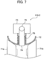
- FIG. 7 is a cross-sectional view illustrating another variable speed reducing mechanism, which is a variable speed reducing mechanism 118 - 2 , with the semi-sphere-shaped roller 72 being partially enlarged.
- the variable speed reducing mechanism 118 - 2 of FIG. 7 includes an elastic member 76 such as a spring that is disposed around the first shaft 74 and is supported by the first shaft 74 .
- the elastic member 76 that functions as an elastic body has one end that is in contact with the semi-sphere-shaped roller 72 and an opposed end that is in contact with the retaining member 73 .
- the semi-sphere-shaped roller 72 in the variable speed reducing mechanism 118 - 2 is supported to be slidable in the axial direction relative to the first shaft 74 .
- the semi-sphere-shaped roller 72 is biased by the elastic member 76 in the axial direction of the first shaft 74 toward the spherical center of the semi-sphere-shaped roller 72 . Due to the biasing of the semi-sphere-shaped roller 72 by the elastic member 76 , the pressing force of the semi-sphere-shaped roller 72 and the input side conical roller 71 a and the pressing force of the semi-sphere-shaped roller 72 and the output side conical roller 71 b increase, and therefore the respective frictional forces also increase, so that the driving force is stably transmitted. According to this configuration, the load to be applied to the motor 44 here is controlled more accurately to a constant load.
- the elastic member 76 presses (biases) the semi-sphere-shaped roller 72 to the side face of the input side conical roller 71 a and the side face of the output side conical roller 71 b , the elastic member 76 may also function as a pressing body.
- FIG. 8A is a side view illustrating a rotatable driving mechanism 800 to be applicable to the variable speed reducing mechanisms 118 - 1 and 118 - 2 described above.
- FIG. 8B is a front view illustrating the rotatable driving mechanism 800 of FIG. 8A .
- the rotatable driving mechanism 800 to the semi-sphere-shaped roller 72 includes a worm wheel 77 , a worm gear 78 , and a worm gear shaft 79 . Both ends of the worm gear shaft 79 are supported by the support plates 41 and 42 .
- a torque limiter 43 ′ is mounted on one end of the worm gear shaft 79 .
- the outer ring of the torque limiter 43 ′ is fixed to the support plate 41 to brake with slip torque. This configuration is referred to as a torque brake 45 .
- the worm wheel 77 is mounted on one end of the second shaft 75 .
- the worm wheel 77 is disposed to connect the driving with the worm gear 78 .
- the first shaft 74 and the second shaft 75 are attached to the retaining member 73 so that the semi-sphere-shaped roller 72 mounted on the first shaft 74 becomes rotatable due to rotation of the second shaft 75 . Due to the large speed reduction ratio by the worm gear 78 and the worm wheel 77 , the semi-sphere-shaped roller 72 becomes capable of locking the own rotation of the semi-sphere-shaped roller 72 .
- both the variable speed reducing mechanism 118 - 1 and the variable speed reducing mechanism 118 - 2 include the torque brake 45 and a drive train unit 700 .
- the torque brake 45 rotates when a torque equal to or greater than a given value is applied.
- the drive train unit 700 extends from the second shaft 75 to the torque brake 45 .
- the drive train unit 700 locks rotation about the second shaft 75 at a large speed reduction ratio.
- the rotatable driving mechanism 800 functions as an assisting device to perform control of a tension force accurately.
- Processing circuitry includes a programmed processor, as a processor includes circuitry.
- a processing circuit also includes devices such as an application specific integrated circuit (ASIC), digital signal processor (DSP), field programmable gate array (FPGA), and conventional circuit components arranged to perform the recited functions.
- ASIC application specific integrated circuit
- DSP digital signal processor
- FPGA field programmable gate array
Landscapes
- Controlling Rewinding, Feeding, Winding, Or Abnormalities Of Webs (AREA)
- Handling Of Sheets (AREA)
- Handling Of Continuous Sheets Of Paper (AREA)
- Ink Jet (AREA)
Abstract
Description
Claims (7)
Applications Claiming Priority (2)
| Application Number | Priority Date | Filing Date | Title |
|---|---|---|---|
| JP2018051384A JP7087507B2 (en) | 2018-03-19 | 2018-03-19 | Tension control device for the object to be transported, device for transporting the object to be transported, liquid discharge device, and image forming device |
| JP2018-051384 | 2018-03-19 |
Publications (2)
| Publication Number | Publication Date |
|---|---|
| US20190283472A1 US20190283472A1 (en) | 2019-09-19 |
| US10744803B2 true US10744803B2 (en) | 2020-08-18 |
Family
ID=67903856
Family Applications (1)
| Application Number | Title | Priority Date | Filing Date |
|---|---|---|---|
| US16/356,619 Expired - Fee Related US10744803B2 (en) | 2018-03-19 | 2019-03-18 | Tension controller, medium conveying device incorporating the tension controller, and image forming apparatus incorporating the medium conveying device |
Country Status (2)
| Country | Link |
|---|---|
| US (1) | US10744803B2 (en) |
| JP (1) | JP7087507B2 (en) |
Families Citing this family (5)
| Publication number | Priority date | Publication date | Assignee | Title |
|---|---|---|---|---|
| CN110315861B (en) | 2018-03-28 | 2022-05-13 | 精工爱普生株式会社 | Scanning device |
| JP2019218199A (en) * | 2018-06-22 | 2019-12-26 | 理想科学工業株式会社 | Transport device |
| CN113580764B (en) | 2020-05-01 | 2022-11-22 | 株式会社理光 | Roll medium holding device and image forming apparatus |
| JP7767975B2 (en) * | 2022-02-21 | 2025-11-12 | セイコーエプソン株式会社 | Printing device and transport control method |
| CN117125523B (en) * | 2023-09-07 | 2024-04-23 | 深圳市尚水智能股份有限公司 | Roll-changing material splicing method, roll-changing material splicing device and computer-readable storage medium |
Citations (11)
| Publication number | Priority date | Publication date | Assignee | Title |
|---|---|---|---|---|
| JPH1191998A (en) | 1997-09-22 | 1999-04-06 | Shibaura Mechatronics Corp | Roll paper type recording device |
| JP2006151651A (en) | 2004-11-30 | 2006-06-15 | Sato Corp | Printing paper take-up device |
| US20110063391A1 (en) | 2009-09-15 | 2011-03-17 | Yoshio Miyamoto | Sheet feeder and image forming apparatus including same |
| US20110180648A1 (en) * | 2010-01-22 | 2011-07-28 | Alps Electric Co., Ltd | Intermediate transfer medium conveying device and thermal transfer line printer using the same |
| JP2012206859A (en) | 2011-03-17 | 2012-10-25 | Ricoh Co Ltd | Sheet feeding device and image forming device |
| JP2015129028A (en) | 2014-01-06 | 2015-07-16 | 株式会社リコー | Rolled recording medium holding mechanism, rolled paper feeder and image forming apparatus |
| US20160130110A1 (en) | 2014-11-12 | 2016-05-12 | Ricoh Company, Ltd. | Roll retainer, and image forming apparatus |
| JP2016102029A (en) | 2014-03-18 | 2016-06-02 | 株式会社リコー | Roll body holding device and image forming apparatus |
| US20170217719A1 (en) | 2016-02-01 | 2017-08-03 | Ricoh Company, Ltd. | Roll holder and printer including same |
| US20180009244A1 (en) * | 2015-03-25 | 2018-01-11 | Fujifilm Corporation | Image forming apparatus and image forming method |
| JP2018008396A (en) | 2016-07-12 | 2018-01-18 | 株式会社リコー | Transportation mechanism and image formation device |
Family Cites Families (6)
| Publication number | Priority date | Publication date | Assignee | Title |
|---|---|---|---|---|
| JPS4813344Y1 (en) * | 1968-09-07 | 1973-04-11 | ||
| JPH09269038A (en) * | 1996-03-29 | 1997-10-14 | Isuzu Motors Ltd | Friction car type continuously variable transmission |
| JP5158354B2 (en) * | 2008-03-10 | 2013-03-06 | セイコーエプソン株式会社 | Rolled recording material conveying apparatus and recording apparatus |
| JP2011152670A (en) * | 2010-01-26 | 2011-08-11 | Canon Inc | Recording apparatus |
| JP2015054500A (en) * | 2013-09-13 | 2015-03-23 | 株式会社リコー | Image forming apparatus and roll print medium conveyance control method |
| JP2015227231A (en) * | 2014-05-30 | 2015-12-17 | キヤノン株式会社 | Take-up device, recording apparatus, and control method for take-up device |
-
2018
- 2018-03-19 JP JP2018051384A patent/JP7087507B2/en active Active
-
2019
- 2019-03-18 US US16/356,619 patent/US10744803B2/en not_active Expired - Fee Related
Patent Citations (12)
| Publication number | Priority date | Publication date | Assignee | Title |
|---|---|---|---|---|
| JPH1191998A (en) | 1997-09-22 | 1999-04-06 | Shibaura Mechatronics Corp | Roll paper type recording device |
| JP2006151651A (en) | 2004-11-30 | 2006-06-15 | Sato Corp | Printing paper take-up device |
| US20110063391A1 (en) | 2009-09-15 | 2011-03-17 | Yoshio Miyamoto | Sheet feeder and image forming apparatus including same |
| JP2011062820A (en) | 2009-09-15 | 2011-03-31 | Ricoh Co Ltd | Sheet feeder and image forming apparatus |
| US20110180648A1 (en) * | 2010-01-22 | 2011-07-28 | Alps Electric Co., Ltd | Intermediate transfer medium conveying device and thermal transfer line printer using the same |
| JP2012206859A (en) | 2011-03-17 | 2012-10-25 | Ricoh Co Ltd | Sheet feeding device and image forming device |
| JP2015129028A (en) | 2014-01-06 | 2015-07-16 | 株式会社リコー | Rolled recording medium holding mechanism, rolled paper feeder and image forming apparatus |
| JP2016102029A (en) | 2014-03-18 | 2016-06-02 | 株式会社リコー | Roll body holding device and image forming apparatus |
| US20160130110A1 (en) | 2014-11-12 | 2016-05-12 | Ricoh Company, Ltd. | Roll retainer, and image forming apparatus |
| US20180009244A1 (en) * | 2015-03-25 | 2018-01-11 | Fujifilm Corporation | Image forming apparatus and image forming method |
| US20170217719A1 (en) | 2016-02-01 | 2017-08-03 | Ricoh Company, Ltd. | Roll holder and printer including same |
| JP2018008396A (en) | 2016-07-12 | 2018-01-18 | 株式会社リコー | Transportation mechanism and image formation device |
Also Published As
| Publication number | Publication date |
|---|---|
| JP2019163116A (en) | 2019-09-26 |
| US20190283472A1 (en) | 2019-09-19 |
| JP7087507B2 (en) | 2022-06-21 |
Similar Documents
| Publication | Publication Date | Title |
|---|---|---|
| US10744803B2 (en) | Tension controller, medium conveying device incorporating the tension controller, and image forming apparatus incorporating the medium conveying device | |
| US7722180B2 (en) | Liquid droplet discharge apparatus including duplex recording medium transport unit | |
| US8573769B2 (en) | Image forming apparatus | |
| US7811015B2 (en) | Printing apparatus and conveyance control method | |
| US11021338B2 (en) | Sheet conveying device and image forming apparatus incorporating the sheet conveying device | |
| EP3636439A1 (en) | Roll device, roll apparatus, head maintenance device, and liquid discharge apparatus | |
| US8979236B1 (en) | Image forming apparatus | |
| JP4913711B2 (en) | Image forming apparatus | |
| JP4897966B2 (en) | Image forming apparatus | |
| US11014380B2 (en) | Image forming apparatus with pre-heat and post-heat control | |
| JP5048413B2 (en) | Image forming apparatus | |
| CN114364541B (en) | Device for controlling the tension applied to a flexible member | |
| JP2016023014A (en) | Ink-jet recording device | |
| JP5219638B2 (en) | Inkjet recording device | |
| JP7151298B2 (en) | Wiping device, head maintenance device, device for ejecting liquid | |
| JP2021014112A (en) | Honeycomb core platen for media transport | |
| JP7115174B2 (en) | Device for ejecting liquid | |
| JP2005096146A (en) | Recording apparatus | |
| JP7163698B2 (en) | MEDIUM CONVEYING DEVICE AND LIQUID EXJECTING DEVICE | |
| JP2019163117A (en) | Image formation apparatus and control method | |
| JP2017222096A (en) | Image forming apparatus | |
| JP4377138B2 (en) | Image recording device | |
| US8047647B2 (en) | Fluid ejecting apparatus | |
| JP2020199634A (en) | Carriage and image formation device | |
| JP2005041124A (en) | Recording device |
Legal Events
| Date | Code | Title | Description |
|---|---|---|---|
| AS | Assignment |
Owner name: RICOH COMPANY, LTD., JAPAN Free format text: ASSIGNMENT OF ASSIGNORS INTEREST;ASSIGNOR:HONDA, RYO;REEL/FRAME:048625/0282 Effective date: 20190315 |
|
| FEPP | Fee payment procedure |
Free format text: ENTITY STATUS SET TO UNDISCOUNTED (ORIGINAL EVENT CODE: BIG.); ENTITY STATUS OF PATENT OWNER: LARGE ENTITY |
|
| STPP | Information on status: patent application and granting procedure in general |
Free format text: NON FINAL ACTION MAILED |
|
| STPP | Information on status: patent application and granting procedure in general |
Free format text: NOTICE OF ALLOWANCE MAILED -- APPLICATION RECEIVED IN OFFICE OF PUBLICATIONS |
|
| ZAAA | Notice of allowance and fees due |
Free format text: ORIGINAL CODE: NOA |
|
| ZAAB | Notice of allowance mailed |
Free format text: ORIGINAL CODE: MN/=. |
|
| STCF | Information on status: patent grant |
Free format text: PATENTED CASE |
|
| FEPP | Fee payment procedure |
Free format text: MAINTENANCE FEE REMINDER MAILED (ORIGINAL EVENT CODE: REM.); ENTITY STATUS OF PATENT OWNER: LARGE ENTITY |
|
| LAPS | Lapse for failure to pay maintenance fees |
Free format text: PATENT EXPIRED FOR FAILURE TO PAY MAINTENANCE FEES (ORIGINAL EVENT CODE: EXP.); ENTITY STATUS OF PATENT OWNER: LARGE ENTITY |
|
| STCH | Information on status: patent discontinuation |
Free format text: PATENT EXPIRED DUE TO NONPAYMENT OF MAINTENANCE FEES UNDER 37 CFR 1.362 |
|
| FP | Lapsed due to failure to pay maintenance fee |
Effective date: 20240818 |