US10739728B2 - Molecular clock - Google Patents
Molecular clock Download PDFInfo
- Publication number
- US10739728B2 US10739728B2 US16/233,982 US201816233982A US10739728B2 US 10739728 B2 US10739728 B2 US 10739728B2 US 201816233982 A US201816233982 A US 201816233982A US 10739728 B2 US10739728 B2 US 10739728B2
- Authority
- US
- United States
- Prior art keywords
- gas cell
- output
- frequency
- signal
- waveguide
- Prior art date
- Legal status (The legal status is an assumption and is not a legal conclusion. Google has not performed a legal analysis and makes no representation as to the accuracy of the status listed.)
- Active
Links
- 238000001686 rotational spectrum Methods 0.000 claims abstract description 17
- 230000007704 transition Effects 0.000 claims description 29
- JJWKPURADFRFRB-UHFFFAOYSA-N carbon oxide sulfide Natural products O=C=S JJWKPURADFRFRB-UHFFFAOYSA-N 0.000 claims description 21
- 230000004044 response Effects 0.000 claims description 15
- 239000013078 crystal Substances 0.000 claims description 12
- -1 carbonyl sulfide compound Chemical class 0.000 claims description 11
- 239000000523 sample Substances 0.000 claims description 9
- 239000010453 quartz Substances 0.000 claims description 5
- VYPSYNLAJGMNEJ-UHFFFAOYSA-N silicon dioxide Inorganic materials O=[Si]=O VYPSYNLAJGMNEJ-UHFFFAOYSA-N 0.000 claims description 5
- 239000000758 substrate Substances 0.000 claims 3
- 230000005672 electromagnetic field Effects 0.000 abstract description 5
- 230000006641 stabilisation Effects 0.000 abstract description 3
- 238000011105 stabilization Methods 0.000 abstract description 3
- 239000007789 gas Substances 0.000 description 95
- 210000004027 cell Anatomy 0.000 description 76
- 230000003595 spectral effect Effects 0.000 description 48
- QGZKDVFQNNGYKY-UHFFFAOYSA-N Ammonia Chemical compound N QGZKDVFQNNGYKY-UHFFFAOYSA-N 0.000 description 26
- 239000006185 dispersion Substances 0.000 description 25
- 238000010521 absorption reaction Methods 0.000 description 23
- 230000007774 longterm Effects 0.000 description 19
- 238000001228 spectrum Methods 0.000 description 11
- 229910021529 ammonia Inorganic materials 0.000 description 10
- 230000005540 biological transmission Effects 0.000 description 8
- 238000001514 detection method Methods 0.000 description 8
- 230000000694 effects Effects 0.000 description 8
- 230000010354 integration Effects 0.000 description 7
- 238000000034 method Methods 0.000 description 7
- 238000010586 diagram Methods 0.000 description 6
- 229910000069 nitrogen hydride Inorganic materials 0.000 description 6
- XUIMIQQOPSSXEZ-UHFFFAOYSA-N Silicon Chemical compound [Si] XUIMIQQOPSSXEZ-UHFFFAOYSA-N 0.000 description 5
- 230000003321 amplification Effects 0.000 description 5
- 125000004429 atom Chemical group 0.000 description 5
- 238000003199 nucleic acid amplification method Methods 0.000 description 5
- 229910052710 silicon Inorganic materials 0.000 description 5
- 239000010703 silicon Substances 0.000 description 5
- 238000012935 Averaging Methods 0.000 description 4
- 239000003513 alkali Substances 0.000 description 4
- 230000007423 decrease Effects 0.000 description 4
- 238000005516 engineering process Methods 0.000 description 4
- 238000001704 evaporation Methods 0.000 description 4
- 230000008020 evaporation Effects 0.000 description 4
- 238000001914 filtration Methods 0.000 description 4
- 230000009467 reduction Effects 0.000 description 4
- 238000012546 transfer Methods 0.000 description 4
- 230000005699 Stark effect Effects 0.000 description 3
- 230000000295 complement effect Effects 0.000 description 3
- 238000005259 measurement Methods 0.000 description 3
- 230000008569 process Effects 0.000 description 3
- 239000004065 semiconductor Substances 0.000 description 3
- WEVYAHXRMPXWCK-UHFFFAOYSA-N Acetonitrile Chemical compound CC#N WEVYAHXRMPXWCK-UHFFFAOYSA-N 0.000 description 2
- 150000001340 alkali metals Chemical group 0.000 description 2
- 238000013459 approach Methods 0.000 description 2
- 239000002585 base Substances 0.000 description 2
- 230000008901 benefit Effects 0.000 description 2
- 230000008859 change Effects 0.000 description 2
- 230000001427 coherent effect Effects 0.000 description 2
- 230000008878 coupling Effects 0.000 description 2
- 238000010168 coupling process Methods 0.000 description 2
- 238000005859 coupling reaction Methods 0.000 description 2
- 238000013461 design Methods 0.000 description 2
- 238000004471 energy level splitting Methods 0.000 description 2
- 125000004435 hydrogen atom Chemical group [H]* 0.000 description 2
- 230000007246 mechanism Effects 0.000 description 2
- 238000002156 mixing Methods 0.000 description 2
- 238000011160 research Methods 0.000 description 2
- 229910052701 rubidium Inorganic materials 0.000 description 2
- IGLNJRXAVVLDKE-UHFFFAOYSA-N rubidium atom Chemical compound [Rb] IGLNJRXAVVLDKE-UHFFFAOYSA-N 0.000 description 2
- 238000007789 sealing Methods 0.000 description 2
- 230000035945 sensitivity Effects 0.000 description 2
- 238000004611 spectroscopical analysis Methods 0.000 description 2
- 230000005653 Brownian motion process Effects 0.000 description 1
- IGLNJRXAVVLDKE-NJFSPNSNSA-N Rubidium-87 Chemical compound [87Rb] IGLNJRXAVVLDKE-NJFSPNSNSA-N 0.000 description 1
- 238000000862 absorption spectrum Methods 0.000 description 1
- 229910052783 alkali metal Inorganic materials 0.000 description 1
- 238000004458 analytical method Methods 0.000 description 1
- 230000004888 barrier function Effects 0.000 description 1
- 238000005537 brownian motion Methods 0.000 description 1
- 229910052792 caesium Inorganic materials 0.000 description 1
- TVFDJXOCXUVLDH-UHFFFAOYSA-N caesium atom Chemical compound [Cs] TVFDJXOCXUVLDH-UHFFFAOYSA-N 0.000 description 1
- 230000009028 cell transition Effects 0.000 description 1
- 210000002421 cell wall Anatomy 0.000 description 1
- 238000004891 communication Methods 0.000 description 1
- 230000002860 competitive effect Effects 0.000 description 1
- 239000012141 concentrate Substances 0.000 description 1
- 238000010276 construction Methods 0.000 description 1
- 230000005684 electric field Effects 0.000 description 1
- 230000005669 field effect Effects 0.000 description 1
- 230000006872 improvement Effects 0.000 description 1
- 238000005404 magnetometry Methods 0.000 description 1
- 238000001883 metal evaporation Methods 0.000 description 1
- 229910044991 metal oxide Inorganic materials 0.000 description 1
- 150000004706 metal oxides Chemical class 0.000 description 1
- 238000004377 microelectronic Methods 0.000 description 1
- 229910052757 nitrogen Inorganic materials 0.000 description 1
- 125000004433 nitrogen atom Chemical group N* 0.000 description 1
- 230000003287 optical effect Effects 0.000 description 1
- 230000036961 partial effect Effects 0.000 description 1
- 238000012545 processing Methods 0.000 description 1
- 230000035939 shock Effects 0.000 description 1
- 230000009897 systematic effect Effects 0.000 description 1
- 238000012360 testing method Methods 0.000 description 1
- 230000005641 tunneling Effects 0.000 description 1
- XLYOFNOQVPJJNP-UHFFFAOYSA-N water Substances O XLYOFNOQVPJJNP-UHFFFAOYSA-N 0.000 description 1
Images


Classifications
-
- G—PHYSICS
- G04—HOROLOGY
- G04F—TIME-INTERVAL MEASURING
- G04F5/00—Apparatus for producing preselected time intervals for use as timing standards
- G04F5/14—Apparatus for producing preselected time intervals for use as timing standards using atomic clocks
- G04F5/145—Apparatus for producing preselected time intervals for use as timing standards using atomic clocks using Coherent Population Trapping
-
- H—ELECTRICITY
- H03—ELECTRONIC CIRCUITRY
- H03L—AUTOMATIC CONTROL, STARTING, SYNCHRONISATION, OR STABILISATION OF GENERATORS OF ELECTRONIC OSCILLATIONS OR PULSES
- H03L7/00—Automatic control of frequency or phase; Synchronisation
- H03L7/06—Automatic control of frequency or phase; Synchronisation using a reference signal applied to a frequency- or phase-locked loop
- H03L7/16—Indirect frequency synthesis, i.e. generating a desired one of a number of predetermined frequencies using a frequency- or phase-locked loop
- H03L7/18—Indirect frequency synthesis, i.e. generating a desired one of a number of predetermined frequencies using a frequency- or phase-locked loop using a frequency divider or counter in the loop
- H03L7/197—Indirect frequency synthesis, i.e. generating a desired one of a number of predetermined frequencies using a frequency- or phase-locked loop using a frequency divider or counter in the loop a time difference being used for locking the loop, the counter counting between numbers which are variable in time or the frequency divider dividing by a factor variable in time, e.g. for obtaining fractional frequency division
- H03L7/1974—Indirect frequency synthesis, i.e. generating a desired one of a number of predetermined frequencies using a frequency- or phase-locked loop using a frequency divider or counter in the loop a time difference being used for locking the loop, the counter counting between numbers which are variable in time or the frequency divider dividing by a factor variable in time, e.g. for obtaining fractional frequency division for fractional frequency division
- H03L7/1976—Indirect frequency synthesis, i.e. generating a desired one of a number of predetermined frequencies using a frequency- or phase-locked loop using a frequency divider or counter in the loop a time difference being used for locking the loop, the counter counting between numbers which are variable in time or the frequency divider dividing by a factor variable in time, e.g. for obtaining fractional frequency division for fractional frequency division using a phase accumulator for controlling the counter or frequency divider
-
- G—PHYSICS
- G04—HOROLOGY
- G04F—TIME-INTERVAL MEASURING
- G04F5/00—Apparatus for producing preselected time intervals for use as timing standards
- G04F5/14—Apparatus for producing preselected time intervals for use as timing standards using atomic clocks
-
- H—ELECTRICITY
- H03—ELECTRONIC CIRCUITRY
- H03B—GENERATION OF OSCILLATIONS, DIRECTLY OR BY FREQUENCY-CHANGING, BY CIRCUITS EMPLOYING ACTIVE ELEMENTS WHICH OPERATE IN A NON-SWITCHING MANNER; GENERATION OF NOISE BY SUCH CIRCUITS
- H03B17/00—Generation of oscillations using radiation source and detector, e.g. with interposed variable obturator
-
- H—ELECTRICITY
- H03—ELECTRONIC CIRCUITRY
- H03J—TUNING RESONANT CIRCUITS; SELECTING RESONANT CIRCUITS
- H03J7/00—Automatic frequency control; Automatic scanning over a band of frequencies
-
- H—ELECTRICITY
- H03—ELECTRONIC CIRCUITRY
- H03L—AUTOMATIC CONTROL, STARTING, SYNCHRONISATION, OR STABILISATION OF GENERATORS OF ELECTRONIC OSCILLATIONS OR PULSES
- H03L7/00—Automatic control of frequency or phase; Synchronisation
- H03L7/06—Automatic control of frequency or phase; Synchronisation using a reference signal applied to a frequency- or phase-locked loop
- H03L7/08—Details of the phase-locked loop
- H03L7/099—Details of the phase-locked loop concerning mainly the controlled oscillator of the loop
- H03L7/0991—Details of the phase-locked loop concerning mainly the controlled oscillator of the loop the oscillator being a digital oscillator, e.g. composed of a fixed oscillator followed by a variable frequency divider
- H03L7/0992—Details of the phase-locked loop concerning mainly the controlled oscillator of the loop the oscillator being a digital oscillator, e.g. composed of a fixed oscillator followed by a variable frequency divider comprising a counter or a frequency divider
-
- H—ELECTRICITY
- H03—ELECTRONIC CIRCUITRY
- H03L—AUTOMATIC CONTROL, STARTING, SYNCHRONISATION, OR STABILISATION OF GENERATORS OF ELECTRONIC OSCILLATIONS OR PULSES
- H03L7/00—Automatic control of frequency or phase; Synchronisation
- H03L7/26—Automatic control of frequency or phase; Synchronisation using energy levels of molecules, atoms, or subatomic particles as a frequency reference
-
- H—ELECTRICITY
- H04—ELECTRIC COMMUNICATION TECHNIQUE
- H04B—TRANSMISSION
- H04B1/00—Details of transmission systems, not covered by a single one of groups H04B3/00 - H04B13/00; Details of transmission systems not characterised by the medium used for transmission
- H04B1/06—Receivers
- H04B1/10—Means associated with receiver for limiting or suppressing noise or interference
- H04B1/1027—Means associated with receiver for limiting or suppressing noise or interference assessing signal quality or detecting noise/interference for the received signal
-
- H—ELECTRICITY
- H04—ELECTRIC COMMUNICATION TECHNIQUE
- H04B—TRANSMISSION
- H04B1/00—Details of transmission systems, not covered by a single one of groups H04B3/00 - H04B13/00; Details of transmission systems not characterised by the medium used for transmission
- H04B1/06—Receivers
- H04B1/16—Circuits
- H04B1/18—Input circuits, e.g. for coupling to an antenna or a transmission line
-
- H—ELECTRICITY
- H04—ELECTRIC COMMUNICATION TECHNIQUE
- H04B—TRANSMISSION
- H04B1/00—Details of transmission systems, not covered by a single one of groups H04B3/00 - H04B13/00; Details of transmission systems not characterised by the medium used for transmission
- H04B1/06—Receivers
- H04B1/16—Circuits
- H04B1/30—Circuits for homodyne or synchrodyne receivers
Definitions
- reference signal sources which provide a reference signal having a stable output frequency
- reference signal sources are sometimes simply referred to as “reference sources” or “clocks”.
- Electronic systems in navigation, telecommunication network synchronization and various sensing (e.g. magnetometry) applications typically utilize high performance clocks to help ensure proper operation.
- the use of a high performance clock is particularly important in equipment which may operate in environments in which a global positioning system (GPS) signal is not available (e.g. underwater sensors).
- GPS global positioning system
- other clock features such as compact size and high energy efficiency become increasingly more important.
- Mechanical oscillators such as crystal oscillators (e.g. quartz crystal oscillators) and microelectromechanical systems (MEMS) oscillator have been widely adopted to fulfill such demands. Although excellent in short-term stability, such mechanical oscillators suffer from long-term frequency drift due to disturbances from the environment, such as temperature variation and mechanical vibration. This leads to instability well beyond the parts per billion (10 ⁇ 9 ) level.
- Atomic clocks lock onto the electron transition frequency of atoms.
- an atomic clock improves the long-term frequency stability.
- Outstanding long-term stability may be achieved by atomic clocks, such as those using cesium 133 Cs, rubidium 87 Rb, and hydrogen atoms, which lock the clock signals to electron transition frequencies. Most of these clocks are, however, power hungry and bulky.
- Chip-scale atomic clock (CSAC) technology miniaturizes conventional atomic clocks based upon coherent population trapping (CPT).
- Chip-scale atomic clocks optically probe the hyperfine-state transition of alkali metal atoms and thus can provide excellent long-term stability via a small physical dimension.
- Using optical coherent population trapping (CPT), chip-scale atomic clocks (CSAC) successfully realized clock miniaturization.
- the SA.45s CSAC achieves a frequency stability (expressed as Allan deviation, ( ⁇ y ) of 3.0 ⁇ 10 ⁇ 10 for a short-term averaging time ⁇ of 1 s and 1.0 ⁇ 10 ⁇ 11 for a long-term ⁇ of 10 3 s. It consumes a DC power of 120 mW and occupies a volume of 16 cm 3 .
- CSACs involve complicated construction of electro-optic components and hence have a high cost, which hinders their wide applications.
- the hyperfine transitions used in CSACs is also sensitive to external electric/magnetic fields, which therefore necessitates dedicated shielding in the alkali gas cell for long-term stability.
- Another disadvantage of such CSACs is the long “start-up” time ( ⁇ several minutes), which resultant from the alkali-metal evaporation and related thermal stabilization.
- an electronic servo loop inside a clock typically have a maximum loop bandwidth limited by the absolute linewidth of the spectrum under probing, which is down to kHz-level for CSACs.
- the resultant low bandwidth (hence slow response time) of the servo loop degrades the capability of correcting fast-changing frequency deviations caused by, for example, clock vibration.
- a molecular clock which utilizes a rotational spectral line of gaseous molecules.
- Such a clock is able to generate a highly stable clock signal.
- Such a clock is also capable of achieving frequency stability characteristics which are the same as or similar to those achieved using a chip-scale atomic clock (CSAS).
- a molecular clock utilizes a rotational spectral line of gaseous molecules in sub-THz region.
- molecules remain in gas phase under a wide temperature range are used since such molecules do not require no atom evaporation (i.e. a gas cell heater typically utilized in traditional atomic clocks for alkali evaporation, as noted above, is not required).
- a gas cell heater typically utilized in traditional atomic clocks for alkali evaporation is not required.
- This instant turn-on characteristic makes the molecular clock described herein suitable for use in numerous applications which require a real-time response. Eliminating the need for a gas cell heater thus enables a molecular clock having the aforementioned instantaneous “turn-on” feature and also leads to a reduction in size.
- a molecular clock provided in accordance with the concepts described herein are able to achieve an absolute line width of about 1 MHz which is on the order of 1,000 times that of a CSAC and has a loop bandwidth of about 100 kHz. Such a relatively wide loop bandwidth results in a molecular clock which is robust under vibration.
- the molecular clock described herein is insensitive to electromagnetic field variation, which results in hyperfine energy level splitting.
- CMOS complementary metal oxide semiconductor
- a rotational-mode molecular clock based upon the absorption spectrum of carbonyl sulfide 16 O 12 C 32 C
- a 65-nm complementary metal-oxide-semiconductor (CMOS) silicon integrated circuit (IC) molecular clock (i.e. a molecular clock chip) is coupled to a waveguide gas cell.
- CMOS complementary metal-oxide-semiconductor
- a new physical mechanism i.e. a rotational spectrum of linear polar molecules may be utilized for clock generation (e.g. carbonyl sulfide 16 O 12 C 32 S, for example in sub-THz region of 200 ⁇ 300 GHz).
- clock generation e.g. carbonyl sulfide 16 O 12 C 32 S, for example in sub-THz region of 200 ⁇ 300 GHz.
- other gaseous molecules having a linear structure may be used and that operation in other RF frequency ranges (e.g. frequency ranges below 200 GHz) is possible and in some applications may be preferred or even necessary.
- molecular clocks described herein have a resonance with a higher quality factor and absorption intensity, which enables better short-term frequency stability.
- the volume of the gas cell required by molecular clocks described herein is reduced to volume levels in the range of cubic centimeters (cm 3 ), thereby resulting in a clock which occupies an area/volume which is small compared with area/volume occupied by conventional clocks having similar performance characteristics (i.e. the concepts described herein result in clock miniaturization).
- the rotational spectrum of OCS and two clock prototypes are studies for the rotational spectrum of OCS and two clock prototypes.
- an instrument-based molecular clock prototype utilizing a high order harmonic dispersion curve of a rotational spectral line, an Allan deviation comparable with that of a CSAC and ten (10) times better than that achieved with ammonia clocks has been measured.
- the molecular clocks described herein also share the fast “start-up” feature of ammonia clocks, since OCS also keeps gas phase above ⁇ 50° C.
- the achieved time-domain response of a molecular clock provided in accordance with the concepts described herein is 1000 times faster than a CSAC, which results in excellent frequency stability even under a vibrating environment as well as other environments.
- FIG. 1 is a block diagram of a molecular clock locking to a zero-crossing point of a dispersion curve ( FIG. 1A );
- FIG. 1A is a plot of a dispersion curve
- FIG. 2 is a block diagram of a molecular clock
- FIG. 3 is a block diagram of a molecular clock
- FIG. 4 a block diagram of a molecular clock
- FIG. 5 is a perspective view of a waveguide gas cell
- FIG. 5A is a plot of measured S parameters (S11 and S21) of a gas cell vs. frequency
- FIG. 5B is a plot of transmission of a gas cell vs. frequency
- FIG. 6 is a block diagram of a fractional-N phase-locked loop (PLL) for a transmitter, such as the transmitter used in the system of FIG. 1 ;
- PLL phase-locked loop
- FIG. 7 is a schematic diagram of a receiver, such as the receiver used in the system of FIG. 1 ;
- FIG. 8 is plot of measured phase noise vs. frequency
- FIG. 8A is plot of receiver noise equivalent power (NEP) vs. frequency
- FIG. 9 is an illustration of a packaged CMOS molecular clock module
- FIG. 9A is a isometric view of an illustrative waveguide gas cell
- FIG. 9B is a plot of a measured dispersion curve having a signal-to-noise ratio (SNR) of 445 or 53 dB using a molecular clock module of FIG. 9 ;
- SNR signal-to-noise ratio
- FIG. 10 is a plot of measured instantaneous frequency of a closed-loop clock and free running VCXO vs. time for a molecular clock module
- FIG. 10A is a plot of measured Allen Deviation vs. averaging time for a molecular clock module
- FIG. 11 is a plot of intensity vs. frequency which illustrates a simulated absorption coefficient within 0.1 ⁇ 1 THz of Carbonyl sulfide ( 16 O 12 C 32 S, blue) and Ammonia ( 14 N 1 H 3 , red) under pressure of 10 Pascal;
- FIG. 12 is plot of transmission vs. frequency at injected RF power of 0.1 ⁇ W with a measured line profile at f 0 versus pressure in a WR4.3 waveguide gas cell;
- FIG. 13 is plot of peak absorption vs. frequency at injected RF power of 0.1 ⁇ W;
- FIG. 14 is plot of transmission vs. frequency at an injected RF power of 1 ⁇ W;
- FIG. 15 is plot of peak absorption vs. frequency at injected RF power of 1 ⁇ W with a measured line profile at f0 versus injected RF power in a WR4.3 waveguide gas cell with an OCS pressure of 5 Pascal;
- FIG. 17 is plot of Allen deviation vs. frequency with an assumed OCS pressure of 5 Pascal, an assumed noise temperature (T noise,Rx ) of a heterodyne receiver of 2.97 ⁇ 10 4 K or a noise figure (NF) of 20 dB and an assumed noise equivalent power (NEP) of a homodyne receiver of 100 pW/ ⁇ square root over (H) ⁇ z;
- T noise,Rx assumed noise temperature
- NF noise figure
- NEP assumed noise equivalent power
- WMS wavelength modulation spectroscopy
- FIG. 19 is a series of plots of measured fundamental, 3 rd harmonic, and 5 th harmonic dispersion curves of 267.530 GHz spectral line of OCS with an OCS pressure of 10 Pascal;
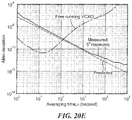
- FIGS. 20-20B are a series of plots illustrating measured instantaneous frequency and overlapping Allan deviation.
- the measured instantaneous frequency of the instrument based molecular clock locking onto fundamental, 3 rd harmonic and 5 th harmonic dispersion curves of 267.530 GHz spectral line of OCS are shown in 22 , 22 ( a ) and 22 ( b ), respectively.
- the RF power is ⁇ 13 dBm.
- the OCS pressure is 10 Pascal; and
- FIGS. 20C-20E show the respective measured overlapping Allan deviations.
- isotopes include, but are not limited to 16 O 12 C 33 S, 16 O 12 C 34 S, 16 O 13 C 32 S and 18 O 12 C 32 S.
- a molecular clock 10 includes a radio frequency (RF) signal source 12 (here illustrated as a voltage-controlled crystal oscillator (VCXO) which provides a clock signal having a frequency f vcxo at an output thereof.).
- the phase noise of signal source 12 is represented as a noise source (“VCXO Noise”) having an input referred noise spectrum density denoted as V xo,n .
- V xo,n Signals from the noise source and baseband circuitry, having a transfer characteristic as shown in FIG. 1A , are combined to produce a signal V xo . which is provided to the RF signal source VCXO.
- the signal source 12 provides an RF signal having a frequency fvcxo to a transmitter circuit (Tx) 14 which may process the signal provided thereto by amplifying, frequency shifting (e.g. upconverting or multiplying and/or downconverting), or otherwise processing the RF input signal provided thereto.
- Transmitter circuit Tx provides an RF transmit signal a frequency fc at an output thereof.
- An output port of the transmitter circuit Tx is coupled to an RF input of a gas cell 16 .
- An illustrative gas cell will be described in detail herein below.
- gas cell utilizes gaseous molecules having a linear structure such that the molecular clock utilizes a rotational spectral line of such gaseous molecules to generate a reference signal having a high degree of stability as will become apparent from the description herein below.
- a molecular clock utilizing rotational spectral lines of gaseous molecules is capable of achieving frequency stability characteristics which are the same as or similar to those achieved using a chip-scale atomic clock (CSAS).
- a molecular clock utilizes a rotational spectral line of gaseous molecules in the sub-THz region.
- frequencies selected from other than the sub-THz frequency range e.g. higher or lower than the sub-THz range
- the rotational lines distribute from the microwave to the THz frequency range (GHz ⁇ THz) and most frequencies have the potential to be used in the clock.
- molecules which remain in gas phase under a wide temperature range are used since such molecules do not require atom evaporation (e.g. a gas cell heater typically utilized in conventional atomic clocks for alkali evaporation, as noted above, Is not required).
- a molecular clock which can be instantaneously “turned-on” is provided. This instant turn-on characteristic makes the molecular clock described herein suitable for use in numerous applications which require a real-time response.
- eliminating the need for a gas cell heater enables a molecular clock having the aforementioned instantaneous “turn-on” feature and also leads to a reduction in size.
- a molecular clock provided in accordance with the concepts described herein are able to achieve an absolute line width of about 1 MHz which is on the order of 1,000 times that of a CSAC and has a loop bandwidth of about 100 kHz. Such a relatively wide loop bandwidth results in a molecular clock which is robust under vibration.
- Receiver circuit Rx receives RF signals from the gas cell, appropriately processes (e.g. down-converts or detects e.g. via a square law detector) the RF signals provided thereto and provides a receiver output signal (e.g. a baseband signal) at an output thereof.
- a receiver output signal e.g. a baseband signal
- the receiver Rx implements square law detection (thus no local oscillator signal is required).
- the receiver output signal (e.g. an intermediate frequency (IF) signal) includes receiver noise which is here schematically illustrated as being added to the receiver output signal via a receiver noise source.
- the receiver output signal is provided to a baseband circuit 20 where the signal is gain adjusted and filtered (here with a low pass filter characteristic) and fed back to signal source 12 .
- a sub-THz signal is generated by the VCXO (which may include, for example, a frequency multiplier chain).
- the receiver receives the signals fed thereto and generates a signal having a frequency corresponding to frequency difference between the carrier frequency of a probing signal f c and f 0 which signal is converted to an error signal V r .
- Frequency locking is then established by feeding the error signal V r back to an input of the VCXO after amplification (with gain of G) and low-pass filtering via baseband circuit 20 .
- G DC K v ⁇ K r ⁇ G>> 1 (Eq. 1) In which:
- K v is the transfer response of the signal source VCXO and transmitter circuit
- G corresponds to the baseband gain.
- noise sources there exists two major noise sources in the system of FIG. 1 : (1) the phase noise of VCXO with an input referred noise spectrum density of V xo,n ; and (2) the noise of sub-THz transceiver with a noise spectrum density of V r,n . Both of the noise sources are reduced (and ideally, entirely suppressed) by the open loop gain G DC after locking, if located within the loop bandwidth.
- the noise spectrum density V r,n dominates
- the short-term Allan deviation ⁇ y of the molecular clock may be expressed by the slope of measured dispersion curve K r and the noise spectrum density V r,n as follows:
- ⁇ is the averaging time
- f 0 represents the spectral line center
- Q is a quality factor of the spectral line
- SNR is the signal to noise ratio of the spectral line.
- the quality factor is determined by several mechanisms including, but not limited to: (1) the natural linewidth, due to disturbance of zero-point vibration of electromagnetic fields, is around 0.1 Hz ( ⁇ 10 12 ) for the sub-THz band; and (2) under low pressure, Doppler effect from the Brownian motion causes spectral-line broadening.
- Equation (2) by assuming a Lorentz line profile, the short term Allen deviation ⁇ y can also be expressed as the product of quality factor Q and SNR.
- a molecular clock locking to the fundamental dispersion curve produces a clock signal having a short-term stability characteristic which is better than a short-term stability characteristic of a clock signal produced by a molecular clock locking to a harmonic dispersion curve.
- an illustrative embodiment of a molecular clock 30 includes a voltage controlled crystal oscillator 32 (VCXO) which generates a 10 MHz reference signal and provides the reference signal to an input of a transmit RF signal generator 34 (i.e. an RF transmit signal source).
- the RF transmit signal source provides an RF output signal to the input of a multiplier (or upconverter) circuit 36 (which may, for example be implemented as a so-called multiplier chain).
- Multiplier circuit receives the RF signal provided thereto from the RF source at a first frequency and provides at an output thereof a second RF signal at a higher frequency (i.e. a multiple of the frequency of the RF input signal).
- the multiplier chain transmitter fed by the VCXO generates an output signal having a frequency in the sub tera Hertz (sub-THz) frequency range.
- the output of the multiplier chain transmitter is coupled to an input of a waveguide gas cell 38 .
- the waveguide gas cell is provided as a rectangular waveguide appropriate for operation in the sub-THz frequency range (e.g. a WR4.3 gas cell).
- the waveguide gas cell includes a gas inlet/outlet through which waveguide gas cell receives molecules having a rotational spectrum of linear polar molecules.
- An example of one such molecular structure is a carbonyl sulfide compound (OCS) having a rotational spectrum of linear polar molecules in millimeter-wave and terahertz frequency ranges.
- OCS carbonyl sulfide compound
- An OCS has a characteristic of having a low temperature coefficient and robustness against external magnetic fields.
- a carbonyl sulfide compound having a rotational spectrum of linear polar molecules in the sub-terahertz (THz) frequency range is used.
- other gases may be used including but not limited to CH 3 CN, SO 2 , H 2 O and HCN.
- the linear OCS molecule when rotating, the linear OCS molecule can be approximated as a rigid rotor with quantized rotational energy levels (indicated by quantum number J).
- the molecular clock described herein is substantially insensitive to electromagnetic field variation, which results in hyperfine energy level splitting.
- a molecular clock having enhanced robustness to electric/magnetic-field disturbance and a high-speed close-loop adjustment of frequency error results in a clock having a timing stability which is higher than conventional clocks.
- An output of the waveguide gas cell is coupled to an RF input of a sub-THz heterodyne receiver 40 .
- an Rx RF signal generator 42 provides a local oscillator (LO) signal to an LO input of the receiver.
- the transmitter provides an RF signal to an RF input of the sub-THz heterodyne receiver (e.g. via the waveguide gas cell) and the Rx RF signal generator provides an LO signal to the LO input of the sub-THz heterodyne receiver.
- the sub-THz heterodyne receiver provides an intermediate frequency (IF) signal at an IF output thereof.
- IF intermediate frequency
- the IF signal produced by the sub-THz heterodyne receiver has a frequency corresponding to a frequency difference between the frequency of the RF signal (designated f c ) and the frequency of the LO signal (designated f 0 ).
- the IF signal is converted to an error signal V r .
- the IF output of the sub-THz heterodyne receiver is coupled to an IF low noise amplifier 44 which amplifies the signal provided thereto and provides a suitably amplified signal at the IF frequency to a bandpass filter 46 which appropriately filters the amplified IF signal.
- the filtered IF signal is then provided to a detector 48 (which may comprise a rectifier, for example).
- the detector produces and envelope signal which is coupled to an of a lock-in amplifier 50 .
- Frequency locking is thus established by feeding the error signal V r back to the crystal oscillator signal source VCXO after amplification with a low noise amplifier (LNA) having a gain of G and appropriate filtering (e.g. using a filter having a low-pass or a band-pass filtering characteristic to improve frequency selectivity by significantly attenuating signals at frequencies other than the IF frequency).
- LNA low noise amplifier
- FIG. 2 corresponds to a clock prototype, which adopts a filter having a band pass filter characteristic (i.e. a BPF) for IF frequency and a filter having filter having a low pass filter characteristic (i.e. a LPF) for baseband.
- the illustrative embodiment of FIG. 3 corresponds to a chip-scale prototype, which only requires a low pass filter.
- K v is a transfer response of the transmitter (Tx);
- K r is a transfer response of the receiver (Rx).
- K r is the slope of a measured dispersion curve (e.g. as shown in FIG. 1A ).
- a portion of the VCXO output signal s coupled to a first input port of a frequency counter 54 and a second input port of the frequency counter is coupled to receive a reference signal Vref having a frequency of 10 MHz from a Rubidium atomic frequency standard signal source 56 .
- Vref a reference signal having a frequency of 10 MHz from a Rubidium atomic frequency standard signal source 56 .
- an instantaneous frequency may be obtained using a frequency counter with a total measurement time of 4000 s (e.g. as shown in FIG. 10A ).
- a molecular clock 60 includes a waveguide gas cell 62 having a gas inlet/outlet 62 a configured to be coupled to a vacuum pump or any other a device capable of removing gas molecules from a sealed volume in order to leave behind a partial vacuum.
- the waveguide gas cell is configured to receive gas molecules having a rotational spectrum of linear polar molecules such as any of the types described herein.
- One example of such a molecular structure is a carbonyl sulfide compound (OCS) having a rotational spectrum of linear polar molecules in millimeter-wave and terahertz frequency ranges.
- OCS carbonyl sulfide compound
- a carbonyl sulfide compound having a rotational spectrum of linear polar molecules in the sub-terahertz (THz) frequency range is used.
- other molecules may be used.
- the factors to be considered in selecting a specific molecule to use in a specific application include, but are not limited to: stability under environment disturbances (for long-term stability), sparsity of the adjacent spectral line (for symmetry), absorption intensity (for SNR) and frequency (for hardware implementation).
- the waveguide gas cell also include a gas inlet port 63 a at which gas molecule are enter the waveguide gas cell and a gas outlet port 63 b at which gas molecule exit the waveguide gas cell.
- the waveguide gas cell also includes an RF input port and an RF output port 64 a , 64 b each having vacuum seal structures provided therein such that gas enter or exit the waveguide cell through the waveguide cell RF input and output ports.
- the molecular clock further includes a CMOS integrated circuit 66 (i.e. a chip) comprising a transmitter 68 and a receiver 70 (and hence the transmitter and receiver are provided as CMOS circuits).
- CMOS integrated circuit 66 i.e. a chip
- An output of the transmitter is coupled to the RF input port of the waveguide gas cell through a chip-to-waveguide transition 72 .
- the RF output port of the waveguide gas cell is coupled to an input of the receiver through a chip-to-waveguide transition 74 .
- the transmitter includes a delta-sigma phased lock loop (PLL) with FSK modulation and the receiver includes a square law detector and lock-in detection circuitry.
- PLL phased lock loop
- the transmitter provides a reference signal to the receiver (here illustrated as having a frequency of 16 KHz) and the receiver receives the RF signal from the waveguide gas cell.
- the receiver In response to the signals provided thereto, the receiver produces an IF signal having a frequency corresponding to a frequency difference between the frequency of the RF signal (designated f c ) and the frequency of the signal provided thereto from the waveguide gas cell (designated f 0 ).
- the IF signal is converted to a differential error signal+/ ⁇ V r and is coupled to an amplifier 76 (here illustrated as an operation amplifier (or Op-Amp) which amplifies the signal provided thereto and provides a suitably amplified signal at the IF frequency to a filter 78 (which may have, for example, a low pass or a band pass filter characteristic).
- the appropriately amplified and filtered signal is then provided to differential control terminals and differential crystal oscillator signal source (VCXO) 80 which in turn provides a feedback signal to the transmitter.
- the feedback signal corresponds to an 80 MHz pulse train. Frequency locking is thus established by feeding the error signal V r produced by the receiver back to the differential VCXO after appropriate amplification and filtering.
- the molecular clock further includes a DC bias signal input through which a DC bias signal is provided to a power supply 82 .
- the power supply provides power to the CMOS circuits (e.g. the transmitter and receiver) as is generally known.
- the molecular clock further includes a control word signal input through which a digital control word (e.g. a steam of digital bits) are provided through an interface 84 (e.g. an SPI) to digitally controllable circuits and components (e.g. the transmitter and receiver and various components thereof).
- a digital control word e.g. a steam of digital bits
- an interface 84 e.g. an SPI
- the frequency of the clock is controlled by the phase-locked loop, which in some embodiments can be adjusted with the 40-bit resolution. In other embodiments, higher or lower resolution may be used (i.e. higher or lower than 40-bit resolution).
- the CMOS chip package may be implemented in silicon using a conventional 65 nm low power CMOS process.
- the feedback circuit and/or the gas cell may also be provided as part of the integrated circuit.
- a molecular clock 90 which may be the same as or similar to the molecular clock described above in conjunction with FIG. 3 is shown.
- the illustrative molecular clock of FIG. 4 corresponds to a complementary metal-oxide-semiconductor (CMOS) a molecular clock.
- CMOS complementary metal-oxide-semiconductor
- the waveguide gas cell contains a carbonyl sulfide compound (OCS) having a rotational spectrum of linear polar molecules in the millimeter through sub-terahertz (THz) frequency ranges.
- OCS carbonyl sulfide compound
- other gases may be used including but not limited to CH 3 CN, SO 2 , H 2 O and HCN.
- SNR signal-to-noise
- the length of the waveguide gas cell is selected to achieve a maximum or near maximum or optimized SNR.
- an appropriate waveguide gas cell e.g. cross-section sectional shape, length, width height, etc. . . . ) for use in a particular application.
- the intensity of two sidebands of the FSK signal is then shaped by the line profile (“shaped meaning being determined by the absorption of the line profile). Therefore, any frequency errors (defined as the frequency difference between the frequency of the transmitter signal f C and the frequency of the local oscillator signal f 0 provided to the receiver CMOS—i.e. f C ⁇ f 0 ) will cause envelope fluctuation with a period of 1/f m due to imbalance of two sidebands.
- the frequency error is converted to the error voltage by a square-law detector and lock-in detector at a frequency of f m in the receiver Rx.
- a feedback signal is provided to the differential voltage controlled crystal oscillator (VCXO) of the transmitter Tx to establish a dynamic frequency compensation system.
- VCXO differential voltage controlled crystal oscillator
- the transmitter TX in FIG. 1 may substantially refer to TX RF generator 34 and multiplier chain 36 of FIG. 2 . It also refers to DSM PLL with FSK modulation.
- the transmitters TX of FIG. 2 and FIG. 3 are different. However, they serve for the same purpose of providing a probing signal at a desired frequency (e.g. a probing signal having a desired frequency in the GHz-THz frequency range).
- an RF power of 50 ⁇ W and OCS pressure of 10 Pascal are chosen to maximize short-term frequency stability of the molecular clock.
- measured FWHM and peak absorption may be about 1.548 MHz and 36.9%, respectively.
- transmit Tx and receive Rx integrated circuits may be implemented on the same chip or independently.
- Transmit Tx and receive Rx integrated circuits may be implemented independently to avoid direct coupling path of sub-THz signal on chip.
- the direct coupling path results in DC level shifting of the dispersion curve and eventually leads to frequency error.
- PLL phase-locked loop
- the PLL also performs frequency-shift-keying (FSK) modulation for WMS, with f m of 16 kHz and ⁇ f of 1 MHz.
- an illustrative metallic rectangular waveguide gas cell which may be the same as or similar to the waveguide gas cells described above in FIGS. 2 and 3 , has an RF input, an RF output and a gas inlet and outlet.
- the waveguide gas cell is provided having a rectangular cross-sectional shape.
- OCS is introduced into the waveguide gas cell.
- An RF source is coupled to the RF input and an RF detector is coupled to the RF output.
- the waveguide gas cell is provided having dimensions of 1.092 ⁇ 0.546 mm 2 (and thus corresponds to WR-4.3) and a length of 14 cm.
- the waveguide gas cell is designed to provide maximum signal strength, and fits into only 5.6-cm 3 volume with a meander profile.
- curve WGGS illustrates simulated absorption coefficients within 0.1 ⁇ 1 THz of Carbonyl sulfide ( 16 O 12 C 32 S, blue) and Ammonia ( 14 N 1 H 3 , red) under pressure of 10 Pascal while curve CGS corresponds to a measured Doppler-limited linewidth based upon a wide cylindrical gas cell at room temperature.
- NH 3 has a 2 ⁇ lower due to lighter weight of molecule.
- the collision between OCS molecules and the cell wall causes spectral broadening.
- the transmission percentage of the cylinder gas cell is less that the transmission percentage of waveguide gas cell.
- collision results in the cylindrical gas cell having a line width of 573 kHz ( 4.7 ⁇ 10 5 ).
- a fractional-N phase-locked loop (PLL) for a transmitter such as any of the transmitters described above in conjunction with FIGS. 2-4 includes a harmonic oscillator cascaded by a multiplier chain to generate a probing signal.
- the embodiment of FIG. 6 illustrates a 224 ⁇ 242 GHz fractional-N phase-locked loop (PLL) for a transmitter with a 57.8 GHz harmonic oscillator cascaded by a multiplier chain to generate the probing signal.
- a 40-bit Mash 1-1-1 ⁇ modulator enables a frequency resolution of 10 ⁇ 12 .
- FSK modulation is performed by resetting the control word of fractional-N PLL based on a FSK counter.
- the f m and ⁇ f of FSK are selectable with a resolution of 3-bit.
- the measured output power of transmitter Tx and the noise equivalent power (NEP) for the receiver Rx are ⁇ 20.2 dBm and 0.5 nW/ ⁇ square root over (Hz) ⁇ , respectively, including the ⁇ 10 dB loss of quartz probe.
- the passive integrator and gain unit are put off-chip for the convenience of loop parameter adjustment.
- a sub-THz power detector on the receive Rx side, a sub-THz power detector, a low noise operational amplifier (op-amp) and an on-chip lock-in detector are integrated to demodulate the probing sub-THz signal.
- the waveguide-to-chip transition based upon a waveguide E-plane quartz probe is designed to bridge the CMOS chip with the WR4.3 waveguide gas cell.
- the receiver includes a transistor (e.g. an NMOS transistor) biased under sub-threshold and utilized as a square law power detector.
- the receiver further includes a low noise folded cascode op-amp which further amplifies the baseband signal.
- An error signal produced by the cascode op-amp is detected by an on-chip lock-in detector, which is clocked by a signal having a frequency f m .
- a chip-to-waveguide transition (such as that described in conjunction with FIGS. 2-4 ) using a quartz probe may be used to extract an RF signal from the circuit.
- a voltage controlled crystal oscillator (VCXO) and passive integrator are arranged off-chip to allow for loop parameter adjustment. It should be appreciated, however, that in other embodiments the VCXO and passive integrator may be arranged on-chip.
- the output power of a signal from the transmitter Tx is ⁇ 20.2 dBm at a frequency of 231.061 GHz, which includes the loss of the chip-to-waveguide transition ( ⁇ 10 dB).
- the saturation effect of the molecules is still under the saturation threshold which means sufficient high power level of probing signal will pull the molecules off the equilibrium. This effect then reduces the absorption ratio of the spectral line.
- a receiver Rx which may be the same as or similar to the receiver described in conjunction with FIGS. 1-4 and 7 , achieves a measured phase noise of ⁇ 68.4 dBc/Hz with frequency offset of 1 MHz.
- NEP noise equivalent power
- integrated circuits which may be the same as or similar to the integrated circuits described in conjunction with FIGS. 2-4, 6 and 7 may be assembled in a package (i.e. a housing) coupled to a waveguide gas cell (herein comprising a WR4.3 waveguide) and a vacuum pump.
- the waveguide meanders along a straight line length (i.e. as measured along a central longitudinal axis of the housing in which a channels is provided) of about 30 cm.
- the housing has input to accept DC bias, SPI and error signals as well as a 8-MHz signal from a VCXO.
- a SNR of 445 or 53 dB with unit bandwidth is obtained under an OCS pressure of 5 Pascal.
- FIG. 9A is an illustrative waveguide gas cell 62 ′ which may be functionally the same as or similar to any of the gas cells described hereinabove in conjunction with FIGS. 1, 2, 3, 4, 5, and 9 and suitable for use with the molecular clock described in conjunction with FIG. 9 .
- the gas cell 62 ′ has first (or upper) and second (or lower) plates having channels provided therein. When the first and second plates are properly aligned and joined, the channels for a waveguide having inputs and outputs as described above.
- the molecular clock is locked onto the zero-crossing point of the dispersion curve.
- the measured dispersion curve has an SNR of 445 or 53 dB.
- a measured instantaneous frequency of closed-loop clock and a free running VCXO is shown to be within 4000 s.
- the VCXO is disturbed in short-term due to the limited SNR, the long-term stability is improved by the spectral line locking (i.e. while disturbing the short term stability, the long term stability is enhanced).
- the CMOS molecular clock consumes a total DC power of 66 mW, excluding the VCXO.
- the total physical volume of CMOS molecular clock is 50 cm 3 .
- Table I shows measured parameters of a CMOS molecular clock, an instrument based molecular clock (denoted below as “Instrument MC”) and prior art clocks (i.e. a pair of CSACs, and an NH 3 Clock) taken respectively from: [1] D. Ruffieux, et al., ISSCC , pp. 48-49, February 2011; [2] Microsemi. QuantumTM, SA.54s chip scale atomic clock, 2017; and [3] D. J. Wineland, IEEE Trans. Instr. Meas ., pp. 122-132, June 1979 as shown.
- the CMOS clock is still inferior, at least in some respects, to an instrument based clock as shown in Table I, which is mainly limited by SNR, further performance enhancement is highly achievable by loss reduction and a heterodyne detection.
- the clock Due to the 880 KHz linewidth, the clock has a loop bandwidth ⁇ 1000 time that of a CSAC. Excluding the VCXO, it consumes a DC power of 66 mW and has a volume of 50 cm 3 . Power consumption of 40 mW and volume of 10 cm 3 are predicted by adopting crystal free molecular clock design and permanent vacuum sealing.
- the short-term stability of a clock is determined by the product of signal-to-noise ratio (SNR) and quality factor ( ) of the detected spectral line.
- SNR signal-to-noise ratio
- quality factor quality factor
- the linear OCS molecule when rotating, the linear OCS molecule can be approximated as a rigid rotor with quantized rotational energy levels (indicated by quantum number J).
- each J-state has 2J+1 degenerated states, explaining the higher absorption in sub-THz than in microwave range.
- population of molecules decreases exponentially with the molecule energy due to Boltzmann's distribution. Beyond ⁇ 500 GHz where maximum absorption occurs, this effect becomes dominant and causes absorption decrease.
- a plurality of measure curves show that under increasingly higher pressure, the more significant inter-molecular collisions become the limiting factor for the spectral line profile.
- FIG. 13 a result summary shows that pressure-induced broadening becomes dominant for pressure above ⁇ 1 Pascal in a WR-4.3 waveguide gas cell, such as that described above in conjunction with FIG. 10 .
- the incident power for J+1 ⁇ J transition goes beyond a certain threshold value, the population of molecules on J-state will be gradually depleted, causing saturation.
- state-of-the-art sensitivity performance of CMOS homodyne detectors (using Schottky-barrier diode or field-effect transistor) and CMOS heterodyne receivers (using a frequency mixer driven by a local oscillator) is assumed.
- the molecular clock should operate slightly above the Doppler-limited pressure and saturation power thresholds.
- a wavelength modulation spectroscopy (WMS) is adopted to probe the spectral line.
- WMS wavelength modulation spectroscopy
- a center frequency f c of a sub-THz signal varies with a modulation frequency of f m and a frequency deviation of ⁇ f, where f m ⁇ f ⁇ FWHM.
- f c ⁇ f 0 the envelope signal V env (t) of the sub-THz signal fluctuates periodically according to the absorption intensity of OCS.
- a lock-in detection of the envelope signal V env (t) is then conducted at fundamental and harmonic frequencies of f m .
- the measured instantaneous frequency and Allan deviation are shown.
- the measurement time for each curve is 4000 s.
- the predicted Allan deviation based on the measured transceiver noise V r,n may be determined using known techniques and the slope of zero-crossing point K r is also included.
- the fundamental dispersion curve defeats the others due to higher SNR.
- the SNR for the fundamental, 3 rd and 5 th harmonic dispersion curves shown in FIG. 5 above are 2.14 ⁇ 10 4 , 1.18 ⁇ 10 4 and 3.64 ⁇ 10 3 , respectively.
- Chip-scale integration on silicon of such a device can make a molecular clock of the type described herein competitive with CSAC with respect to cost, power consumption and size.
- CMOS complementary metal-oxide-semiconductor
- CMOS molecular clock is limited by the loss of waveguide-to-chip transition, the phase noise of on-chip PLL, and the noise of homodyne detector. Improved EM and circuit design are necessary to fill the gap between the two prototypes.
- the energy efficiency of the clock can also be enhanced by removing the VCXO, which consumes 10 ⁇ 20 mW of DC power. Crystal free molecular clock is achievable since the usage of VCXO is only for the “start-up” condition.
- a total DC power consumption of ⁇ 40 mW is highly possible.
- the volume of molecular clock can be reduced to below 10 cm 3 .
- the WR4.3 waveguide gas cell only has a volume of 5.7 cm 3 .
- Most of the total 50 cm 3 volume is taken by the vacuum sealing and flange.
- Working with spectral line at higher frequency can further reduce the size of gas cell too.
- the molecular clock in the paper is just on its initial phase, a highly stable, portable and energy efficient time generators is highly predictable.
- the intermediate signal f IF is 950 MHz.
- the modulation signal f m 100 kHz, generated by SR865A, is feeding to E8257D.
- the rotational spectral lines of OCS in sub-THz band provide FWHM of ⁇ 1 MHz, 1000 ⁇ of the electron transition of alkali atoms in CSAC (FWHW ⁇ 1 kHz).
- the modulation frequency f m needs to be roughly 10 ⁇ lower than FWHM.
- a loop filter with 3 dB bandwidth at least 10 ⁇ lower than f m is necessary for further integration.
- f BW ⁇ f m is in demand for loop stability, since a pole nearby f m exists for lock-in detection.
- the maximum loop bandwidth is f Bw,max ⁇ 0.1 ⁇ FWHM.
- Molecular clock then has 1000 ⁇ wider loop bandwidth than CSAC. Broader loop bandwidth leads to faster frequency settling. If a disturbance voltage ⁇ V with step function appears, the time response is expressed as:
- V xo ⁇ ( t ) ⁇ ⁇ ⁇ V 1 K V ⁇ K r ⁇ G + e - K V ⁇ K R ⁇ G RC ⁇ t ( 3 )
- T s RC ⁇ ln( K v K r G )/( K v K r G ).
- ARC filter with 3 dB cut off frequency of 0.32 Hz is adopted.
- the temperature dependency The temperature change causes pressure variation due to the ideal gas law, which doesn't only broaden the spectral line but also shift the center frequency because of weak collision of molecules.
- the Zeeman effect of the magnetic field is less prominent compared with Stark effect in most molecules. It has frequency shift of 10 ⁇ 10 /Gauss in our case. Thus, a common magnetic field shielding of 100 ⁇ can reduce the magnetic field dependency to 10 ⁇ 12 /Gauss.
Abstract
Description
G DC =K v ·K r ·G>>1 (Eq. 1)
In which:
In which:
G DC =K v ·K r ·G>>1 (Eq. 1)
in which:
| TABLE I |
| PERFORMANCE COMPARISON |
| ADEV (1 s) | ADEV (103 s) | BW (kHz) | Size (cm3) | PDC (Mw) | ||
| CMOS | 2.4 × 10⁻⁹ | 3.8 × 10⁻¹⁰ | <100 | 50 | 66 + 50 |
| Instrument MC | 3.2 × 10⁻¹⁰ | 2.2 × 10⁻¹¹ | <100 | N/A | N/A |
| CSAC [1] | 4 × 10⁻¹⁰ | 3 × 10⁻¹⁰ | N/A | N/A | 26 |
| CSAC [2] | 3 × 10⁻¹⁰ | 1 × 10⁻¹¹ | <0.1 | 16 | 120 |
| NH3 Clock [3] | 6 × 10⁻¹⁰ | 2 × 10⁻¹⁰ | <10 | 103 | 3 × 10³ |
T s =RC·ln(K v K r G)/(K v K r G).
Claims (19)
Priority Applications (1)
| Application Number | Priority Date | Filing Date | Title |
|---|---|---|---|
| US16/233,982 US10739728B2 (en) | 2018-01-29 | 2018-12-27 | Molecular clock |
Applications Claiming Priority (2)
| Application Number | Priority Date | Filing Date | Title |
|---|---|---|---|
| US201862623214P | 2018-01-29 | 2018-01-29 | |
| US16/233,982 US10739728B2 (en) | 2018-01-29 | 2018-12-27 | Molecular clock |
Publications (2)
| Publication Number | Publication Date |
|---|---|
| US20190235445A1 US20190235445A1 (en) | 2019-08-01 |
| US10739728B2 true US10739728B2 (en) | 2020-08-11 |
Family
ID=67392082
Family Applications (1)
| Application Number | Title | Priority Date | Filing Date |
|---|---|---|---|
| US16/233,982 Active US10739728B2 (en) | 2018-01-29 | 2018-12-27 | Molecular clock |
Country Status (2)
| Country | Link |
|---|---|
| US (1) | US10739728B2 (en) |
| WO (1) | WO2019147376A1 (en) |
Cited By (2)
| Publication number | Priority date | Publication date | Assignee | Title |
|---|---|---|---|---|
| US11190196B2 (en) * | 2019-10-18 | 2021-11-30 | Massachusetts Institute Of Technology | Systems and methods for suppressing even harmonics in a molecular clock |
| US11515646B2 (en) | 2019-10-24 | 2022-11-29 | Massachusetts Institute Of Technology | Integrated circuit-to-waveguide slot array coupler |
Families Citing this family (8)
| Publication number | Priority date | Publication date | Assignee | Title |
|---|---|---|---|---|
| GB201700621D0 (en) | 2017-01-13 | 2017-03-01 | Guest Ryan Dominic | Method,device and kit for the aseptic isolation,enrichment and stabilsation of cells from mammalian solid tissue |
| WO2020076402A1 (en) | 2018-10-12 | 2020-04-16 | Imra America, Inc. | Compact microresonator frequency comb |
| US10620589B1 (en) * | 2018-12-26 | 2020-04-14 | Texas Instruments Incorporated | Millimeter wave chip scale atomic clock |
| US11188032B2 (en) * | 2019-02-08 | 2021-11-30 | Texas Instruments Incorporated | Molecular clock with delay compensation |
| US20220221583A1 (en) | 2020-04-13 | 2022-07-14 | Imra America, Inc. | Ultra-low phase noise millimeter-wave oscillator and methods to characterize same |
| US11601156B2 (en) * | 2020-07-06 | 2023-03-07 | Mediatek Inc. | Apparatus and methods for improved transmit power |
| FI20215400A1 (en) * | 2021-04-01 | 2022-10-02 | Teknologian Tutkimuskeskus Vtt Oy | High-frequency reference device |
| US11342928B1 (en) * | 2021-08-30 | 2022-05-24 | Texas Instruments Incorporated | Molecular clock calibration |
Citations (14)
| Publication number | Priority date | Publication date | Assignee | Title |
|---|---|---|---|---|
| US2602897A (en) * | 1948-09-18 | 1952-07-08 | Rca Corp | Stabilization of microwave oscillators |
| US2602835A (en) * | 1949-03-30 | 1952-07-08 | Rca Corp | Microwave spectroscopy |
| US2695361A (en) * | 1950-12-01 | 1954-11-23 | Rca Corp | Pulse comparison system and method |
| US2811644A (en) * | 1955-01-26 | 1957-10-29 | Rca Corp | Gas resonance system |
| US5838206A (en) | 1995-09-29 | 1998-11-17 | Observatoire Cantonal De Neuchatel | Active hydrogen maser atomic frequency standard |
| US5892250A (en) * | 1996-01-30 | 1999-04-06 | Nec Corporation | Semiconductor integrated circuit chip |
| US20070247241A1 (en) | 2006-04-19 | 2007-10-25 | Sarnoff Corporation | Batch-fabricated, rf-interrogated, end transition, chip-scale atomic clock |
| US20100111750A1 (en) | 2008-10-31 | 2010-05-06 | Honeywell International Inc. | Methods for introduction of a reactive material into a vacuum chamber |
| US20160190670A1 (en) | 2014-12-28 | 2016-06-30 | International Business Machines Corporation | Direct and compact chip to waveguide transition |
| US20160291549A1 (en) * | 2015-03-31 | 2016-10-06 | Texas Instruments Incorporated | Rotational transition based clock, rotational spectroscopy cell, and method of making same |
| US20180159547A1 (en) * | 2016-12-01 | 2018-06-07 | Texas Instruments Incorporated | Method and Apparatus To Reduce The Leakage Rate of a Hermetic Cavity |
| US20190072447A1 (en) * | 2017-09-07 | 2019-03-07 | Texas Instruments Incorporated | Pressure sensing using quantum molecular rotational state transitions |
| US20190204786A1 (en) * | 2017-12-29 | 2019-07-04 | Texas Instruments Incorporated | Molecular Atomic Clock With Wave Propagating Rotational Spectroscopy Cell |
| US10493722B2 (en) * | 2017-09-07 | 2019-12-03 | Texas Instruments Incorporated | Hermetically sealed molecular spectroscopy cell with dual wafer bonding |
-
2018
- 2018-12-27 US US16/233,982 patent/US10739728B2/en active Active
- 2018-12-27 WO PCT/US2018/067642 patent/WO2019147376A1/en active Application Filing
Patent Citations (14)
| Publication number | Priority date | Publication date | Assignee | Title |
|---|---|---|---|---|
| US2602897A (en) * | 1948-09-18 | 1952-07-08 | Rca Corp | Stabilization of microwave oscillators |
| US2602835A (en) * | 1949-03-30 | 1952-07-08 | Rca Corp | Microwave spectroscopy |
| US2695361A (en) * | 1950-12-01 | 1954-11-23 | Rca Corp | Pulse comparison system and method |
| US2811644A (en) * | 1955-01-26 | 1957-10-29 | Rca Corp | Gas resonance system |
| US5838206A (en) | 1995-09-29 | 1998-11-17 | Observatoire Cantonal De Neuchatel | Active hydrogen maser atomic frequency standard |
| US5892250A (en) * | 1996-01-30 | 1999-04-06 | Nec Corporation | Semiconductor integrated circuit chip |
| US20070247241A1 (en) | 2006-04-19 | 2007-10-25 | Sarnoff Corporation | Batch-fabricated, rf-interrogated, end transition, chip-scale atomic clock |
| US20100111750A1 (en) | 2008-10-31 | 2010-05-06 | Honeywell International Inc. | Methods for introduction of a reactive material into a vacuum chamber |
| US20160190670A1 (en) | 2014-12-28 | 2016-06-30 | International Business Machines Corporation | Direct and compact chip to waveguide transition |
| US20160291549A1 (en) * | 2015-03-31 | 2016-10-06 | Texas Instruments Incorporated | Rotational transition based clock, rotational spectroscopy cell, and method of making same |
| US20180159547A1 (en) * | 2016-12-01 | 2018-06-07 | Texas Instruments Incorporated | Method and Apparatus To Reduce The Leakage Rate of a Hermetic Cavity |
| US20190072447A1 (en) * | 2017-09-07 | 2019-03-07 | Texas Instruments Incorporated | Pressure sensing using quantum molecular rotational state transitions |
| US10493722B2 (en) * | 2017-09-07 | 2019-12-03 | Texas Instruments Incorporated | Hermetically sealed molecular spectroscopy cell with dual wafer bonding |
| US20190204786A1 (en) * | 2017-12-29 | 2019-07-04 | Texas Instruments Incorporated | Molecular Atomic Clock With Wave Propagating Rotational Spectroscopy Cell |
Non-Patent Citations (41)
| Title |
|---|
| Antonio, et al.; "Frequency stabilization in nonlinear micromechanical oscillators"; Nature Communications; 3:806; May 1, 2012; 6 Pages. |
| Bottom; "A History of the Quartz Crystal Industry in the USA"; Proceedings of the 35th Annual Frequency Control Symposium; pp. 3-12; May 1981; IEEE; 15 Pages. |
| Camparo; "The rubidium atomic clock and basic research"; 2007 American Institute of Physics; S-0031; Nov. 2007; 12 Pages. |
| Cox; et al.; "Zeeman Effect of Some Linear and Symmetric-Top Molecules"; Physical Review; vol. 101; No. 4; Feb. 15, 1956; pp. 1298-1304; 7 Pages. |
| Cyr, et al.; "All-optical microwave frequency standard: a proposal"; IEEE Transactions on Instrumentation and Measurement; vol. 42; No. 2; Apr. 1993; pp. 640-649; 10 Pages. |
| DeNatale, et al.; "Compact, low-power chip-scale atomic clock"; 2008 IEEE/ION Position, Location and Navigation Symposium; May 5, 2008; pp. 67-70; 4 Pages. |
| Esnault, et al.; "A compact cold-atom frequency standard based on coherent population trapping"; Frequency Control Symposium (FCS); 2012 IEEE International, May 2012; pp. 1-3; 3 Pages. |
| Essen, et al.; "An atomic standard of frequency and time interval: a caesium resonator"; 1955 Nature Publishing Group; Aug. 13, 1955; vol. 176; pp. 280-282; 3 Pages. |
| Essen; "Frequency Standardization"; Proc. IEE-Part II; Power Eng.; Jan. 1951; pp. 154-164; 11 Pages. |
| Essen; "Frequency Standardization"; Proc. IEE—Part II; Power Eng.; Jan. 1951; pp. 154-164; 11 Pages. |
| Fernández, et al.; "CSAC characterization and its impact on GNSS clock augmentation performance"; Sensors 2017; 17; 370; www.mdpi.com/journal/sensors; Feb. 14, 2017; 19 Pages. |
| Good; "The inversion spectrum of ammonia"; 1946 American Physical Society; Phys. Rev. 70; 213; Aug. 1, 1946; http://courses.washington.edu/phys432/NH3/ammonia_inversion.pdf; 22 Pages. |
| Haesler, et al.; "The integrated swiss miniature atomic clock"; 2013 Joint IEEE Ultrasonics, Ferroelectrics and Frequency Control Society (UFFC), European Frequency and Time Forum (EFTF), and Piezoresponse Force Microscopy (PFM) Symposium; pp. 579-581; 2013 IEEE; 3 Pages. |
| Hershberger, et al.; "servo theory applied to frequency stabilization with spectral lines"; Journal of the Franklin Institute; vol. 249; Issue 5; May 1950; pp. 359-366; 8 Pages. |
| Jet Propulsion Laboratory; Molecular Spectroscopy Catalog; https://spec.jpl.nasa.gov/; p. 2018. |
| Kabourek et al.; "Prague's Emission Fourier Transform Microwave Spectrometer - Design and Preliminary Results"; Radioengineering; vol. 22; No. 4; Dec. 1, 2013; [Retrieved on Feb. 24, 2019]; Retrieved from the Internet: <URL: https://www.radioeng.cz/fulltexts/2013/13_04_1288_1295.pdf>; 8 Pages. |
| Kabourek et al.; "Prague's Emission Fourier Transform Microwave Spectrometer — Design and Preliminary Results"; Radioengineering; vol. 22; No. 4; Dec. 1, 2013; [Retrieved on Feb. 24, 2019]; Retrieved from the Internet: <URL: https://www.radioeng.cz/fulltexts/2013/13_04_1288_1295.pdf>; 8 Pages. |
| Koshelev, et al.; "Speed dependence of collisional relaxation in ground vibrational state of OCS: Rotational behavior"; The Journal of Chemical Physics 136; Mar. 30, 2012; 12 Pages. |
| Lutwak; "The chip-scale atomic clock-recent developments"; 2009 IEEE International Frequency Control Symposium Joint with the 22nd European Frequency and Time Forum; Apr. 20, 2009; pp. 573-577; 5 Pages. |
| Lutwak; "The SA.45S chip-scale atomic clock-early production statistics"; Proceedings of the 43rd Annual Precise Time and Time Interval Systems and Applications Meeting; Nov. 14, 2011; pp. 207-220; 12 Pages. |
| Lutwak; "The chip-scale atomic clock—recent developments"; 2009 IEEE International Frequency Control Symposium Joint with the 22nd European Frequency and Time Forum; Apr. 20, 2009; pp. 573-577; 5 Pages. |
| Lutwak; "The SA.45S chip-scale atomic clock—early production statistics"; Proceedings of the 43rd Annual Precise Time and Time Interval Systems and Applications Meeting; Nov. 14, 2011; pp. 207-220; 12 Pages. |
| Microsemi; "shock and vibration testing of the SA.45s chip scale atomic clock (CSAC) validation build units"; Aug. 2014; White Paper; 36 Pages. |
| Microsemi; Quantum™, "SA.54s chip scale atomic clock"; Jan. 2017; Data Sheet; 4 Pages. |
| Nguyen et. al.; "Towards chip-scale atomic clocks"; 2005 IEEE International Solid-State Circuits Conference (ISSCC); Feb. 7, 2005; Digest of Technical Papers; pp. 84-85; 2 Pages. |
| PCT International Search Report dated Mar. 6, 2019 for International Application No. PCT/US2018/067642; 4 pages. |
| PCT International Written Opinion dated Mar. 6, 2019 for International Application No. PCT/US2018/067642; 5 pages. |
| Rautian; "The Effect of Collisions on the Doppler Broadening of Spectral Lines"; Soviet Physics Uspekhi; vol. 9; No. 5.; Mar.-Apr. 1967; pp. 701-716; 17 Pages. |
| Ruffieux, et al.; "A Low-Power Fully Integrated RF Locked Loop for Miniature Atomic Clock"; 2011 IEEE International Sold-Sate Circuits Conference (ISSCC); pp. 48-49; Feb. 21, 2011; 3 Pages. |
| Supplee, et al.; "Theoretical description of frequency modulation and wavelength modulation spectroscopy"; Applied Optics; vol. 33; No. 27; Sep. 20, 1994; pp. 6294-6302; 9 Pages. |
| Townes; "Atomic clocks and frequency stabilization on microwave spectral lines"; Journal of Applied Physics; vol. 22; No. 11; Nov. 1951; pp. 1365-1372; 9 Pages. |
| Vanier, et al.; "On the signal-to-noise ratio and short-term stability of passive rubidium frequency standards"; IEEE Transactions on Instrumentation and Measurement; vol. IM-30; No. 4, Dec. 1981; pp. 277-282; 6 Pages. |
| Wang et al.; "High-Stability, Miniature Terahertz Molecular Clock on CMOS"; MIT Annual Report 2017 ; Jul. 2017; Retrieved on Mar. 19, 2020 from the Internet: <URL: https://mtlsites.mit.edu/annual_reports/ar2017.html>; Circuits & Systems, 222 pages. |
| Wang et al.; "High-Stability, Miniature Terahertz Molecular Clock on CMOS"; MTL Annual report; Jul. 2017; [Retrieved on Feb. 24, 2019]; Retrieved from the Internet: <URL: https://mtlsites.mit.edu/annual_reports/2017/circuits.pdf> p. 36; 1 Page. |
| Wang, et al.; "Rapid and Energy-Efficient Molecular Sensing Using Dual mm-Wave Combs in 65nm CMOS: A 220-to-320GHz Spectrometer with 5.2mW Radiated Power and 14.6-to-19.5dB Noise Figure"; 2017 IEEE International Solid-State Circuit Conference (ISSCC); Feb. 7, 2017; pp. 18-20; 3 Pages. |
| Wang, et al.; "Robust sub-harmonic mixer at 340 GHz using intrinsic resonances of hammer-head filter and improved diode model"; Journal of Infared, Millimeter, and Terahertz Waves; Nov. 2017; vol. 38; Issue 11; pp. 1397-1415; 19 Pages. |
| Wang, et al; "Duel-Terahertz-Comb Spectrometer on CMOS for Rapid, Wide-Range Gas Detection with Absolute Specificity"; IEEE Journal of Solid-State Circuits (JSSC); vol. 52; No. 12; Dec. 2017; pp. 3361-3372; 12 Pages. |
| Wineland et al.; "Results with the special-purpose ammonia frequency standard"; 31st Annual Symposium on Frequency Control; Jun. 1, 1977; pp. 562-573; 12 Pages. |
| Wineland et al.; "Special Purpose Ammonia Frequency Standard-A Feasibility Study"; IEEE Transactions on Instrumentation and Measurement; vol. IM-28; No. 2; Jun. 1979; pp. 122-132; 11 Pages. |
| Wineland et al.; "Special Purpose Ammonia Frequency Standard—A Feasibility Study"; IEEE Transactions on Instrumentation and Measurement; vol. IM-28; No. 2; Jun. 1979; pp. 122-132; 11 Pages. |
| Youngner, et al.; "A manufacturable chip-scale atomic clock"; Transducers & Eurosensors 2007; The 14th International Conference on Solid-State Sensors, Actuators and Microsystems, Lyon, France; Jun. 10, 2007; pp. 39-44; 2007 IEEE; 6 Pages. |
Cited By (2)
| Publication number | Priority date | Publication date | Assignee | Title |
|---|---|---|---|---|
| US11190196B2 (en) * | 2019-10-18 | 2021-11-30 | Massachusetts Institute Of Technology | Systems and methods for suppressing even harmonics in a molecular clock |
| US11515646B2 (en) | 2019-10-24 | 2022-11-29 | Massachusetts Institute Of Technology | Integrated circuit-to-waveguide slot array coupler |
Also Published As
| Publication number | Publication date |
|---|---|
| US20190235445A1 (en) | 2019-08-01 |
| WO2019147376A1 (en) | 2019-08-01 |
Similar Documents
| Publication | Publication Date | Title |
|---|---|---|
| US10739728B2 (en) | Molecular clock | |
| US7323941B1 (en) | Method and system for operating a laser self-modulated at alkali-metal atom hyperfine frequency | |
| Wang et al. | An on-chip fully electronic molecular clock based on sub-terahertz rotational spectroscopy | |
| US8258877B2 (en) | Feed-back and feed-forward systems and methods to reduce oscillator phase-noise | |
| Boudot et al. | Coherent population trapping resonances in Cs–Ne vapor microcells for miniature clocks applications | |
| Ivanov et al. | Low phase-noise sapphire crystal microwave oscillators: current status | |
| Wang et al. | Chip-scale molecular clock | |
| Wang et al. | A terahertz molecular clock on CMOS using high-harmonic-order interrogation of rotational transition for medium-/long-term stability enhancement | |
| Wang et al. | A CMOS molecular clock probing 231.061-GHz rotational line of OCS with sub-ppb long-term stability and 66-mW DC power | |
| Ivanov et al. | Noise properties of microwave signals synthesized with femtosecond lasers | |
| Drouin et al. | A CMOS millimeter-wave transceiver embedded in a semi-confocal Fabry-Perot cavity for molecular spectroscopy | |
| Deng et al. | Effect of buffer gas ratios on the relationship between cell temperature and frequency shifts of the coherent population trapping resonance | |
| Kim et al. | Chip-scale terahertz carbonyl sulfide clock: An overview and recent studies on long-term frequency stability of OCS transitions | |
| WO2006073597A2 (en) | Method and system for operating a laser self-modulated at alkali-metal atom hyperfine frequence | |
| Riley | The physics of the environmental sensitivity of rubidium gas cell atomic frequency standards | |
| Nemchick et al. | 180-GHz pulsed CMOS transmitter for molecular sensing | |
| Kim et al. | A sub-THz CMOS molecular clock with 20 ppt stability at 10,000 s based on dual-loop spectroscopic detection and digital frequency error integration | |
| Zhao et al. | CPT cesium-cell atomic clock operation with a 12-mW frequency synthesizer ASIC | |
| He et al. | A mm-wave signal generation and background phase alignment technique for scalable arrays | |
| US11190196B2 (en) | Systems and methods for suppressing even harmonics in a molecular clock | |
| Sharma et al. | Complementary metal oxide semiconductor integrated circuits for rotational spectroscopy | |
| WO1994003971A1 (en) | Microwave oscillator with improved phase noise characteristic | |
| Boudot et al. | A solid-mounted resonator-oscillator-based 4.596 GHz frequency synthesis | |
| Wang et al. | 29.5 sub-THz CMOS molecular clock with 43ppt long-term stability using high-order rotational transition probing and slot-array couplers | |
| Kim | Design and Analysis of High-Stability THz Molecular Clock System |
Legal Events
| Date | Code | Title | Description |
|---|---|---|---|
| FEPP | Fee payment procedure |
Free format text: ENTITY STATUS SET TO UNDISCOUNTED (ORIGINAL EVENT CODE: BIG.); ENTITY STATUS OF PATENT OWNER: SMALL ENTITY |
|
| AS | Assignment |
Owner name: MASSACHUSETTS INSTITUTE OF TECHNOLOGY, MASSACHUSET Free format text: ASSIGNMENT OF ASSIGNORS INTEREST;ASSIGNORS:HAN, RUONAN;WANG, CHENG;REEL/FRAME:048058/0208 Effective date: 20181220 Owner name: MASSACHUSETTS INSTITUTE OF TECHNOLOGY, MASSACHUSETTS Free format text: ASSIGNMENT OF ASSIGNORS INTEREST;ASSIGNORS:HAN, RUONAN;WANG, CHENG;REEL/FRAME:048058/0208 Effective date: 20181220 |
|
| FEPP | Fee payment procedure |
Free format text: ENTITY STATUS SET TO SMALL (ORIGINAL EVENT CODE: SMAL); ENTITY STATUS OF PATENT OWNER: SMALL ENTITY |
|
| AS | Assignment |
Owner name: NATIONAL SCIENCE FOUNDATION, VIRGINIA Free format text: CONFIRMATORY LICENSE;ASSIGNOR:MASSACHUSETTS INSTITUTE OF TECHNOLOGY;REEL/FRAME:048567/0353 Effective date: 20190117 |
|
| STPP | Information on status: patent application and granting procedure in general |
Free format text: NON FINAL ACTION MAILED |
|
| STPP | Information on status: patent application and granting procedure in general |
Free format text: NOTICE OF ALLOWANCE MAILED -- APPLICATION RECEIVED IN OFFICE OF PUBLICATIONS |
|
| STPP | Information on status: patent application and granting procedure in general |
Free format text: PUBLICATIONS -- ISSUE FEE PAYMENT VERIFIED |
|
| STCF | Information on status: patent grant |
Free format text: PATENTED CASE |
|
| MAFP | Maintenance fee payment |
Free format text: PAYMENT OF MAINTENANCE FEE, 4TH YR, SMALL ENTITY (ORIGINAL EVENT CODE: M2551); ENTITY STATUS OF PATENT OWNER: SMALL ENTITY Year of fee payment: 4 |