US10734029B2 - Signal processing apparatus, signal processing method, and non-transitory computer-readable storage medium - Google Patents
Signal processing apparatus, signal processing method, and non-transitory computer-readable storage medium Download PDFInfo
- Publication number
- US10734029B2 US10734029B2 US15/971,526 US201815971526A US10734029B2 US 10734029 B2 US10734029 B2 US 10734029B2 US 201815971526 A US201815971526 A US 201815971526A US 10734029 B2 US10734029 B2 US 10734029B2
- Authority
- US
- United States
- Prior art keywords
- sound
- audio signal
- image
- event
- playback
- Prior art date
- Legal status (The legal status is an assumption and is not a legal conclusion. Google has not performed a legal analysis and makes no representation as to the accuracy of the status listed.)
- Active, expires
Links
- 238000012545 processing Methods 0.000 title claims abstract description 28
- 238000003672 processing method Methods 0.000 title claims 3
- 230000005236 sound signal Effects 0.000 claims abstract description 109
- 230000002093 peripheral effect Effects 0.000 claims abstract description 9
- 238000000034 method Methods 0.000 claims description 78
- 230000015654 memory Effects 0.000 claims description 4
- 230000002194 synthesizing effect Effects 0.000 claims 3
- 238000004590 computer program Methods 0.000 claims 1
- 230000008569 process Effects 0.000 description 68
- 238000001514 detection method Methods 0.000 description 58
- 238000003384 imaging method Methods 0.000 description 18
- 230000010365 information processing Effects 0.000 description 18
- 238000004891 communication Methods 0.000 description 8
- 230000006870 function Effects 0.000 description 7
- 238000010586 diagram Methods 0.000 description 4
- 230000009471 action Effects 0.000 description 3
- 239000000470 constituent Substances 0.000 description 3
- 230000007423 decrease Effects 0.000 description 3
- 239000000284 extract Substances 0.000 description 3
- 238000009434 installation Methods 0.000 description 3
- 230000001360 synchronised effect Effects 0.000 description 3
- 238000004458 analytical method Methods 0.000 description 2
- 230000008859 change Effects 0.000 description 2
- 230000006866 deterioration Effects 0.000 description 2
- 238000009877 rendering Methods 0.000 description 2
- 230000008901 benefit Effects 0.000 description 1
- 239000000872 buffer Substances 0.000 description 1
- 238000007796 conventional method Methods 0.000 description 1
- 230000003247 decreasing effect Effects 0.000 description 1
- 230000007613 environmental effect Effects 0.000 description 1
- 238000000605 extraction Methods 0.000 description 1
- 238000010191 image analysis Methods 0.000 description 1
- 238000003702 image correction Methods 0.000 description 1
- 239000000203 mixture Substances 0.000 description 1
- 238000012986 modification Methods 0.000 description 1
- 230000004048 modification Effects 0.000 description 1
- 230000003287 optical effect Effects 0.000 description 1
- 230000002035 prolonged effect Effects 0.000 description 1
- 230000004044 response Effects 0.000 description 1
- 230000000630 rising effect Effects 0.000 description 1
- 238000000926 separation method Methods 0.000 description 1
Images


Classifications
-
- G—PHYSICS
- G11—INFORMATION STORAGE
- G11B—INFORMATION STORAGE BASED ON RELATIVE MOVEMENT BETWEEN RECORD CARRIER AND TRANSDUCER
- G11B27/00—Editing; Indexing; Addressing; Timing or synchronising; Monitoring; Measuring tape travel
- G11B27/10—Indexing; Addressing; Timing or synchronising; Measuring tape travel
- G11B27/19—Indexing; Addressing; Timing or synchronising; Measuring tape travel by using information detectable on the record carrier
- G11B27/28—Indexing; Addressing; Timing or synchronising; Measuring tape travel by using information detectable on the record carrier by using information signals recorded by the same method as the main recording
-
- H—ELECTRICITY
- H04—ELECTRIC COMMUNICATION TECHNIQUE
- H04N—PICTORIAL COMMUNICATION, e.g. TELEVISION
- H04N5/00—Details of television systems
- H04N5/76—Television signal recording
- H04N5/78—Television signal recording using magnetic recording
- H04N5/782—Television signal recording using magnetic recording on tape
- H04N5/783—Adaptations for reproducing at a rate different from the recording rate
-
- G—PHYSICS
- G11—INFORMATION STORAGE
- G11B—INFORMATION STORAGE BASED ON RELATIVE MOVEMENT BETWEEN RECORD CARRIER AND TRANSDUCER
- G11B27/00—Editing; Indexing; Addressing; Timing or synchronising; Monitoring; Measuring tape travel
- G11B27/005—Reproducing at a different information rate from the information rate of recording
-
- G—PHYSICS
- G11—INFORMATION STORAGE
- G11B—INFORMATION STORAGE BASED ON RELATIVE MOVEMENT BETWEEN RECORD CARRIER AND TRANSDUCER
- G11B27/00—Editing; Indexing; Addressing; Timing or synchronising; Monitoring; Measuring tape travel
- G11B27/02—Editing, e.g. varying the order of information signals recorded on, or reproduced from, record carriers
- G11B27/031—Electronic editing of digitised analogue information signals, e.g. audio or video signals
-
- H—ELECTRICITY
- H04—ELECTRIC COMMUNICATION TECHNIQUE
- H04N—PICTORIAL COMMUNICATION, e.g. TELEVISION
- H04N5/00—Details of television systems
- H04N5/76—Television signal recording
- H04N5/91—Television signal processing therefor
Definitions
- the present invention relates to a technique of playing back a sound suitable for a playback image.
- a sound having the same length as that of a moving image is recorded during slow-motion imaging.
- the recorded sound source is separated into a human voice, an impulsion related sound (for example, a hitting sound or kicking sound), and other sounds.
- an impulsion related sound for example, a hitting sound or kicking sound
- the other sounds are directly played back in slow motion, and a process of prolonging the time of the human voice while holding the pitch of the voice is performed.
- an echoing process is performed on the impulsion related sound so that the echo is repetitively played back a number of times.
- This disclosure has been made in consideration of the above problems, and provides a technique for playing back a sound suitable for a playback image.
- a signal processing apparatus for generating a playback audio signal to be played back together with a slow-motion image based on image capturing in a capturing target region which comprises: a first obtaining unit configured to obtain a first audio signal containing a sound in the capturing target region, the first audio signal being based on sound acquisition in a first period shorter than a capturing period corresponding to the slow-motion image; a second obtaining unit configured to obtain a second audio signal containing a sound in a peripheral region of the capturing target region, the second audio signal being based on sound acquisition in a second period longer than the capturing period; and a generation unit configured to synthesize the first audio signal obtained by the first obtaining unit and the second audio signal obtained by the second obtaining unit, thereby generating the playback audio signal to be played back together with the slow-motion image.
- FIG. 1A is a block diagram showing a configuration example of an image/sound playback system
- FIG. 1B is a block diagram showing a hardware configuration example of an information processing apparatus
- FIG. 2 is a schematic view showing an installation image of sports sound microphones and cheer sound microphones
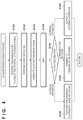
- FIG. 3 is a flowchart of main processing of the information processing apparatus
- FIG. 4 is a flowchart of a slow-motion playback process
- FIG. 5 is a flowchart of an event detection process
- FIG. 6 is a flowchart of a sports sound event detection process
- FIG. 7 is a flowchart of a cheer sound event detection process
- FIG. 8 is a flowchart of a slow-motion-image sound generation process
- FIG. 9 is a flowchart of a reference event selection process
- FIGS. 10A, 10B, and 10C are respectively views showing the data structures of image event information, sports sound event information, and cheer sound event information.
- FIGS. 11A to 11C are images of timing charts showing the results of sound generation and playback according to an embodiment.
- FIG. 1A is a block diagram showing a configuration example of an image/sound playback system according to an embodiment.
- a capturing target is a predetermined sport.
- sounds to be acquired are a sound generated in a sports region (capturing target region) where a sport as a capturing target is performed (for example, a sound generated by a player in a sports field (game field)), and an environmental sound generated from a peripheral space surrounding the sports region of the capturing target (for example, a cheer of spectators in the stand).
- the capturing target region where sounds are collected may also be a stage of an event, and the peripheral space may also be spectator seats.
- the image/sound playback system of this embodiment includes an information processing apparatus 100 , a sports sound microphone 1 , a cheer sound microphone 4 , a camera 10 , a headphone 17 , and surround speakers 18 .
- Each sports sound microphone 1 included in a sports sound microphone group of a plurality of microphones acquires a sound of a target sport (a sound generated from a predetermined region of a capturing target), converts the sound into an electric signal (analog signal), and transmits the signal.
- the sports sound microphone 1 is installed in the direction of a target sport.
- a sports sound acquisition unit 2 functions as a sports sound acquiring means. The sports sound acquisition unit 2 properly amplifies the electric signal of a sound transmitted from the sports sound microphone 1 , converts the analog signal into a digital signal, and transmits the digital signal as a sports sound signal (first sound) to a sports sound storage unit 3 .
- the sports sound storage unit 3 stores the sports sound signal (to be also simply referred to as a sports sound hereinafter) transmitted by the sports sound acquisition unit 2 , together with time information.
- This time information is, for example, information of the time at which the sports sound signal is input to the sports sound storage unit 3 .
- the sports sound storage unit 3 appropriately outputs a sports sound at a designated time to an event detection unit 7 , in accordance with an instruction by a CPU 23 ( FIG. 1B ).
- Each cheer sound microphone 4 included in a cheer sound microphone group of a plurality of microphones acquires a cheer sound in an environment where the target sport is performed (a sound in a peripheral region of a predetermined region of the capturing target), converts the acquired sound into an electric signal (analog signal), and transmits the signal.
- the cheer sound microphone 4 is installed in the direction of spectators.
- FIG. 2 is a schematic view showing an installation image of the sports sound microphones 1 and cheer sound microphones 4 .
- a plurality of sports sound microphones 1 and a plurality of cheer sound microphones 4 are arranged in a stadium 104 where a target sport is performed.
- the stadium 104 includes a sports field 101 , a ground 102 , and stands 103 .
- the target sport is performed in the sports field 101 .
- the ground 102 is a horizontal plane including the sports field 101 .
- the sports sound microphones 1 are installed on the ground 102 .
- the stands 103 spectators watch the target sport and cheer in accordance with the progress of the sport.
- the plurality of sports sound microphones 1 are so arranged as to surround the sports field 101 in order to acquire sports sounds.
- the plurality of cheer sound microphones 4 are arranged in order to acquire sounds generated in the stands. Note that in FIG. 2 , the plurality of sports sound microphones 1 and the plurality of cheer sound microphones 4 are arranged. However, it is also possible to arrange one sports sound microphone and one cheer sound microphone. Alternatively, a sound for playback may also be generated by using only an acquired sound signal of a selected microphone of the plurality of microphones. Furthermore, a signal obtained by separating only the sports sound may also be used as a sports sound signal, by suppressing, with respect to an audio signal acquired by the sports sound microphone 1 , a signal acquired by a nearby cheer sound microphone 4 .
- a cheer sound acquisition unit 5 functions as a cheer sound acquiring means.
- the cheer sound acquisition unit 5 appropriately amplifies a sound electric signal transmitted from the cheer sound microphone 4 , converts the analog signal into a digital signal, and transmits this digital signal as a cheer sound signal (second sound) to a cheer sound storage unit 6 .
- the cheer sound storage unit 6 stores the cheer sound signal (to be also simply referred to as a cheer sound hereinafter) transmitted by the cheer sound acquisition unit 5 , together with time information. This time information is, for example, information of the time at which the cheer sound signal is input to the cheer sound storage unit 6 .
- the cheer sound storage unit 6 appropriately outputs a sports sound at a designated time to the event detection unit 7 in accordance with an instruction from the CPU 23 ( FIG. 1B ).
- the event detection unit 7 analyzes the sports sound stored in the sports sound storage unit 3 , the cheer sound stored in the cheer sound storage unit 6 , and an image stored in an image storage unit 12 . Then, the event detection unit 7 detects an event in the set time interval and the occurrence time of the event, and transmits the detection results to a sound generation unit 8 .
- the sound generation unit 8 Based on the time interval and playback speed of the playback image set via the operation unit 15 and image playback unit 13 and the event occurrence time received from the event detection unit 7 , the sound generation unit 8 extracts necessary sound data (sports sound/cheer sound) from the sports sound storage unit 3 and cheer sound storage unit 6 , and generates an audio signal suitable for the image. The sound generation unit 8 outputs the generated audio signal to the sound playback unit 9 .
- a sound playback unit 9 renders the audio signal received from the sound generation unit into various sound playback formats such as “stereo” and “surround”.
- the sound playback unit 9 transmits the rendered audio signal (including a stereo signal and binaural signal) to various sound playback apparatuses (the headphone 17 and surround speakers 18 ), or to an MUX 16 .
- the camera 10 captures an image of the target sport and transmits a video signal to an imaging unit.
- An imaging unit 11 forms image data by performing an image correction process on the video signal received from the camera 10 (an image obtaining process), and transmits the image data to the image storage unit.
- the image storage unit 12 stores the image data (to be also simply referred to as an image hereinafter) received from the imaging unit 11 , together with time information. This time information is, for example, information of the time at which the image data is input to the image storage unit 12 .
- the image playback unit 13 extracts, from the image storage unit 12 , the image of a playback image time interval designated via the operation unit 15 . Also, the image playback unit 13 transmits information of the playback image time interval designated via the operation unit 15 and information of the playback speed to the event detection unit 7 and sound generation unit 8 . In addition, when starting image playback, the image playback unit 13 transmits a playback start trigger signal to the sound playback unit 9 , and performs image playback at the playback speed designated by the user. This playback start trigger signal is generated in accordance with, for example, a user's instruction transmitted via the operation unit 15 . The image playback unit 13 outputs the played back video signal to an image display unit 14 or the MUX 16 .
- the operation unit 15 accepts various instructions from the user, converts the accepted instructions into control commands, and transmits the commands to the image playback unit 13 .
- These instructions include a playback instruction for normal playback at an actual speed (an equal speed, a onefold speed) or slow-motion playback at a speed lower than that of normal playback.
- the normal playback instruction contains information for specifying the time interval (playback period) and playback speed of a playback image
- the slow-motion playback instruction contains information for specifying the playback time interval and the slow-motion playback speed of a playback image.
- the image display unit 14 displays the video signal received from the image playback unit 13 as an image.
- the MUX 16 forms video/audio stream data by superposing the audio signal received from the sound playback unit 9 and the video signal received from the image playback unit, and outputs the data to a communication unit 19 and an output unit 21 .
- the headphone 17 converts the stereo signal or binaural signal output from the sound playback unit 9 into a sound, and outputs the sound.
- the surround speakers 18 convert the stereo signal or surround signal output from the sound playback unit 9 into a sound, and output the sound.
- the communication unit 19 outputs the video/audio stream signal received from the MUX 16 to the outside via a communication network 20 .
- the communication network 20 indicates the Internet or a general telephone line.
- the video/audio stream formed by the MUX 16 can be output to an apparatus outside the system across the communication network 20 .
- the output unit 21 outputs the video/audio stream formed by the MUX 16 to an external apparatus connected to the output terminal.
- FIG. 1B is a block diagram showing a hardware configuration example of the information processing apparatus 100 .
- a storage unit 22 is a RAM (Random Access Memory) or ROM (Read Only Memory).
- the CPU 23 controls the operation of each constituent element in the information processing apparatus 100 shown in FIG. 1A .
- the CPU 23 is connected to the individual constituent elements of the information processing apparatus 100 shown in FIG. 1A , and the operations of these constituent elements are comprehensively controlled in accordance with instructions for performing processing to be explained below from the CPU 23 .
- the configuration examples of the image/sound playback system and information processing apparatus 100 have been explained above.
- the configuration of the information processing apparatus is not limited to the configuration explained above.
- the sports sound acquisition unit 2 , sports sound storage unit 3 , cheer sound acquisition unit 5 , cheer sound storage unit 6 , imaging unit 11 , and image storage unit 12 may also exist inside an apparatus different from the information processing apparatus 100 .
- FIG. 3 is a flowchart of main processing of the information processing apparatus 100 according to this embodiment.
- processes in steps S 1 and S 2 and processes from step S 3 to step S 6 or S 7 are performed in parallel. That is, FIG. 3 shows a flowchart when playing back an image and sound while performing imaging and sound acquisition.
- the present invention is not limited to this.
- the information processing apparatus 100 may also play back an image and sound by using stored image data and sound data after completing imaging and sound acquisition.
- step S 1 an imaging/sound acquisition process is performed. More specifically, as an image obtaining process, the imaging unit 11 forms image data by performing a developing process and correcting process on a video signal transmitted from the camera 10 .
- the sports sound acquisition unit 2 and cheer sound acquisition unit 5 respectively properly amplify analog signals transmitted from the sports sound microphone 1 and cheer sound microphone 4 , and convert the analog signals into digital signals (audio signals).
- step S 2 the image data and audio signal obtained by imaging and sound acquisition in step S 1 are recorded in the image storage unit 12 , sports sound storage unit 3 , and cheer sound storage unit 6 , together with imaging/sound acquisition time information.
- the operation returns to step S 1 again.
- the image data and sound data obtained by imaging and sound acquisition are sequentially stored in the storage units (the image storage unit 12 , sports sound storage unit 3 , and cheer sound storage unit 6 ). Since the image data and sound data are stored in these storage units together with the time information, data at an arbitrary time can be extracted by designating the time information.
- step S 3 whether the operation unit 15 has accepted an instruction from the user is checked.
- step S 4 the operation advances to step S 5 if the operation unit 15 has accepted an instruction from the user, and returns to step S 3 if not.
- step S 5 the operation unit 15 checks the instruction content. If the instruction content is “normal playback”, the operation advances to a normal playback process in step S 6 .
- the normal playback instruction contains the playback time interval, and the information processing apparatus 100 plays back an image of the designated time interval in synchronism with the audio signal.
- a playback process like this is normally performed in a general image playback apparatus and well known, so an explanation thereof will be omitted.
- step S 3 the operation returns to step S 3 .
- the instruction content is “slow-motion playback”
- the operation advances to step S 7 .
- the slow-motion playback instruction contains the playback time interval and slow-motion playback speed.
- the information processing apparatus 100 performs a slow-motion playback process in accordance with the playback time interval and slow-motion playback speed. Details of this process will be described later with reference to FIG. 4 .
- the operation returns to step S 3 . If the instruction content is “end”, all the processes are terminated, and the main processing is complete.
- FIG. 4 is a flowchart showing the details of the slow-motion playback process in step S 7 of FIG. 3 .
- step S 101 the image playback unit 13 transmits the information of the playback time interval and slow-motion playback speed contained in the slow-motion playback instruction to the event detection unit 7 and sound generation unit 8 .
- step S 102 the event detection unit 7 detects an event by analyzing the image data and sound data in the playback time interval received in step S 101 . This process will be described in detail later with reference to FIG. 5 .
- step S 103 the sound generation unit 8 generates a playback sound signal (slow-motion-image audio signal) to be played back together with a slow-motion image (slow-motion playback video signal) corresponding to the playback time interval and slow-motion playback speed received in step S 101 .
- the sound generation unit 8 generates the slow-motion-image audio signal by extracting and combining the sports sound and cheer sound by different methods. This process will be described in detail later with reference to FIG. 8 .
- step S 104 the MUX 16 superposes the slow-motion-image audio signal generated by the sound generation unit 8 and the slow-motion playback video signal generated by the image playback unit 13 , thereby generating a video/audio stream.
- step S 105 the sound playback unit 9 , image playback unit 13 , and MUX 16 check the output destination.
- output destination information is prestored in the storage unit 22 . The user may also designate the output destination via the operation unit 15 . If the checking result indicates that the output destination includes the image display unit 14 and a playback apparatus such as the headphone 17 or surround speakers 18 , the operation advances to step S 106 . If the output destination is the communication network 20 , the operation advances to step S 107 . If the output destination is an external apparatus, the operation advances to step S 108 .
- step S 106 the image playback unit 13 plays back a slow-motion image at the designated playback speed with respect to the image of the designated time interval, outputs the image to the image display unit 14 , and displays the image on the image display unit 14 .
- the image playback unit 13 outputs a playback start trigger signal to the sound playback unit 9 .
- the sound playback unit 9 outputs the slow-motion-playback audio signal generated by the sound generation unit 8 to the headphone 17 or surround speakers 18 in response to the playback start trigger signal. Consequently, the generated slow-motion-playback audio signal and slow-motion image are synchronously played back.
- the slow-motion playback process is terminated, and the operation returns.
- step S 107 the communication unit 19 transmits the video/audio stream data generated by the MUX 16 in step S 104 to the communication network 20 .
- step S 108 the output unit 21 outputs the video/audio stream data generated by the MUX 16 in step S 104 to an external apparatus connected to the output terminal.
- the slow-motion playback process is terminated, and the operation returns.
- step S 104 the video/audio stream data generated by the MUX 16 in step S 104 is used in the processes in steps S 107 and S 108 , but is not used in step S 106 , so the process in step S 104 may also be performed after the determination in step S 106 .
- FIG. 5 is a flowchart showing details of the event detection process in step S 102 of FIG. 4 .
- the event detection unit 7 obtains image data from the image storage unit 12 in accordance with the playback time interval received from the image playback unit 13 .
- the event detection unit 7 analyzes the image data obtained in step S 201 , thereby detecting an event having occurred in the sport as a capturing target in this time interval.
- the event detection unit 7 performs person recognition and action analysis in the image, detects a specific action unique to the sport as a capturing target (for example, a kick in soccer) as an event, and extracts the time of this specific action (for example, the time at which the direction or speed of the ball largely changes in soccer) as an event occurrence time.
- a specific action unique to the sport for example, a kick in soccer
- the time of this specific action for example, the time at which the direction or speed of the ball largely changes in soccer
- This sort of event detection using an image is widely performed in image recognition and well known, so a detailed explanation thereof will be omitted.
- the storage unit 22 records the detected event as image event information together with the event occurrence time.
- FIG. 10A shows the data structure of the image event information.
- the image event information contains an image event ID 111 , an image event occurrence time 112 , and an image event type 113 .
- the image event ID 111 is a number for identifying event information detected by image analysis.
- the image event occurrence time 112 is the occurrence time of the event corresponding to the image event ID 111 .
- the image event type 113 is the type of event (for example, “kick”, “heading, or “catch” in soccer).
- step S 203 the event detection unit 7 obtains the sound data (sports sound signal/cheer sound signal) from the sports sound storage unit 3 and cheer sound storage unit 6 , in accordance with the playback time interval received from the image playback unit 13 .
- step S 204 the event detection unit 7 detects the event (related to the sports sound) having occurred in the sport as a capturing target by analyzing the sports sound signal obtained in step S 203 , and records the event as sports sound event information together with the event occurrence time and event end time in the storage unit 22 . This process will be described in detail later with reference to FIG. 6 .
- FIG. 10B shows the data structure of the sports sound event information.
- the sports sound event information contains a sports sound event ID 114 , an input channel number 115 , a sports sound event start time 116 , and a sports sound event end time 117 .
- the sports sound event ID 114 is a number for identifying the sports sound event information.
- the input channel number 115 is the number of a channel on which the sound of the sports sound event corresponding to the sports sound event ID 114 (the identification number of the sports sound microphone 1 ) is recorded.
- the sports sound event start time 116 and sports sound event end time 117 are respectively the start time and end time of recording of the sports sound event corresponding to the sports sound event ID 114 .
- the event detection unit 7 merges the image event information ( FIG. 10A ) detected in step S 202 to the sports sound event information ( FIG. 10B ) detected in step S 204 .
- the event detection unit 7 refers to the image event time information (the image event occurrence time 112 ) and the sports sound event time information (the sports sound event start time 116 and sports sound event end time 117 ), and collects events having occurred at the same time as one event.
- the event detection unit 7 may also leave event information existing in only one of the image event information and sports sound event information. This merging process can eliminate the redundancy of event information pertaining to a single event detected from both the image and sports sound, thereby reducing the load on the later sound generation process. Also, even an event which cannot be detected as a sports sound event can be detected by an image. This makes it possible to leave information pertaining to an event which cannot be detected from sound data but may be detected by hearing.
- step S 206 the event detection unit 7 analyses the cheer sound signal obtained in step S 203 , detects a cheer sound event related to the cheer sound, and records the event as cheer sound event information in the storage unit 22 . Details of this process will be described later with reference to FIG. 7 .
- FIG. 10C shows the data structure of the cheer sound event information.
- the cheer sound event information contains a cheer sound event ID 118 , an input channel number 119 , a cheer sound event occurrence time 120 , and a maximum sound pressure 121 .
- the cheer sound event ID 118 is a number for identifying the cheer sound event.
- the input channel number 119 is a channel number on which the sound of the cheer sound event corresponding to the cheer sound event ID 118 is recorded (the identification number of the cheer sound microphone 4 ).
- the cheer sound event occurrence time 120 is the time of recording when the cheer sound event corresponding to the cheer sound event ID 118 has occurred.
- the maximum sound pressure 121 is a maximum sound pressure level from the occurrence time of the cheer sound data corresponding to the cheer sound event ID 118 to the end of the peak of the sound pressure.
- step S 207 a list (event information list) of the cheer sound event information merged in step S 205 and the cheer sound event information detected in step S 206 are output to the sound generation unit 8 .
- the event detection process is terminated, and the operation returns.
- FIG. 6 is a flowchart showing details of the sports sound event detection process in step S 204 of FIG. 5 .
- the event detection unit 7 initializes the sports sound event information list stored in the storage unit 22 .
- the sports sound event information list sequentially stores sports sound event information to be detected hereafter in the process of this flowchart.
- the event detection unit 7 converts the waveform of the sports sound signal obtained in step S 203 into time sound pressure data by calculating the absolute value of the time amplitude of the sports sound signal.
- step S 303 the event detection unit 7 calculates the time average value of the time sound pressure data obtained in step S 302 , and calculates a peak threshold by multiplying the time average value by a predetermined multiple A.
- the predetermined multiple A is a number predetermined based on a target sport, the layout of the sports sound microphones 1 and cheer sound microphones 4 , and the like.
- step S 304 the event detection unit 7 searches for all sound pressure peaks larger than the peak threshold calculated in step S 303 from the time sound pressure data obtained in step S 302 . Then, the event detection unit 7 detects the peak start time of each peak found by the search (the time at which the sound pressure starts rising toward the peak), and records the peak start time in the storage unit 22 .
- Step S 310 Processing from step S 305 to step S 310 is loop processing for each sound pressure peak recorded in step S 304 .
- the event detection unit 7 determines whether the sound pressure decreases to a predetermined value until the next peak start time or the sports sound data end time. This predetermined value can be determined as an arbitrary value. If the sound pressure decreases to the predetermined value (YES in step S 306 ), the operation advances to step S 307 . If not (NO in step S 306 ), the operation advances to step S 308 .
- step S 307 the event detection unit 7 determines the time at which the sound pressure decreases to the predetermined value, as the sports sound event end time 117 .
- step S 308 the event detection unit 7 determines the time immediately before the next sound pressure peak start time, or the sound data end time if there is no next peak, as the sports sound event end time 117 .
- step S 309 the event detection unit 7 forms new sports sound event information, sets the peak start time as the sports sound event start time 116 , stores the sports sound event start time 116 and the sports sound event end time 117 determined in step S 307 or S 308 in the sports sound event information, and adds the sports sound event information to the sports sound event information list.
- the event detection unit 7 adds the input channel number 115 to the sports sound event information. Also, when adding new sports sound event information to the sports sound event information list, the event detection unit 7 issues the sports sound event ID 114 , and stores the sports sound event ID 114 in the sports sound event information to be added. Note that the event detection unit 7 may also store information of the maximum sound peak between the sports sound event start time 116 and sports sound event end time 117 as a maximum pressure value in the sports sound event information.
- step S 310 the sports sound event detection process is terminated, and the operation returns.
- a sound generated by a specific object for example, a sound generated when a player kicks the ball is detected as a sports sound event.
- FIG. 7 is a flowchart showing details of the cheer sound event detection process in step S 206 of FIG. 5 .
- the event detection unit 7 initializes the cheer sound event information list stored in the storage unit 22 .
- the event detection unit 7 converts the waveform of the cheer sound signal obtained in step S 203 into time sound pressure data by calculating the absolute value of the time amplitude of the cheer sound signal.
- the event detection unit 7 calculates a value determined from the time average value of the time sound pressure data obtained in step S 402 , as a sound pressure threshold.
- step S 404 the event detection unit 7 searches the whole cheer sound data for a change point (sound pressure increasing point) at which the sound pressure becomes larger than the sound pressure threshold obtained in step S 403 , and records all times (sound pressure increasing times) found by the search in the storage unit 22 .
- step S 406 the event detection unit 7 determines whether a state in which the sound pressure is higher than the sound pressure threshold continues for a predetermined time interval from the sound pressure increasing time. Note that this time interval can be determined based on a target sport, the size of a place where the sport is performed, and the like. If it is determined that the state in which the sound pressure is higher than the threshold continues for the predetermined time interval or more (YES in step S 406 ), the operation advances to step S 407 . If not (NO in step S 406 ), the operation advances to step S 409 .
- step S 407 the event detection unit 7 detects a maximum sound pressure in the time interval from the sound pressure increasing time to the end of the state in which the sound pressure is higher than the threshold.
- step S 408 the event detection unit 7 forms new cheer sound event information by setting the sound pressure increasing time of the processing target as the cheer sound event occurrence time, stores the input channel number 119 , the cheer sound event occurrence time 120 , and the maximum sound pressure 121 detected in step S 407 in the cheer sound event information, adds the cheer sound event information to the cheer sound event information list, and stores the list in the storage unit 22 .
- the event detection unit 7 issues the cheer sound event ID 118 , and stores the cheer sound event ID 118 in the cheer sound event information to be added.
- step S 409 if all the sound pressure increasing times are completely processed, the loop processing is terminated, the cheer sound event detection process is complete, and the operation returns.
- the event detection unit 7 detects a cheer sound event based not only on the sound pressure increasing time, but also on whether the sound pressure increasing state continues after that. This makes it possible to prevent detection of suddenly generated noise, and detect a part in which the cheers become louder because, for example, a player kicks the ball, as an event.
- FIG. 8 is a flowchart showing details of the slow-motion-image sound generation process in step S 103 of FIG. 4 .
- the sound generation unit 8 forms a new sports sound track and new cheer sound track in the storage unit 22 .
- the sports sound track and cheer sound track are buffers for storing the time waveform data of the sports sound signal and cheer sound signal, respectively.
- the time length of each track is matched with the playback time length of the slow-motion image. This can be calculated based on the playback time interval and playback speed of the slow-motion playback image received from the image playback unit in step S 101 .
- Processing from step S 502 to step S 506 is loop processing for each sports sound event information contained in the sports sound event information list transmitted from the event detection unit 7 .
- the sound generation unit 8 obtains a sports sound from the sports sound event start time 116 (the start timing) to the sports sound event end time 117 (the end timing) by cutout (extraction) from the sports sound storage unit 3 .
- the sound generation unit 8 calculates the timing at which an image obtained at the same time as the sports sound event occurrence time is played back during slow-motion playback, based on the playback time interval and slow-motion playback speed received from the image playback unit in step S 101 of FIG. 4 .
- Tr A ⁇ ( te ⁇ t 1)
- step S 505 the sound generation unit 8 pastes the sports sound cut out in step S 503 onto the sports sound track so that playback starts from the playback timing obtained in step S 504 . This makes it possible to playback the sports sound in synchronism with the timing at which the image at the occurrence time of the sports sound event is played back.
- step S 506 if all pieces of the sports sound event information are completely processed, the loop is terminated, and the operation advances to step S 507 .
- step S 507 the sound generation unit 8 selects an event (reference event) as a reference for synchronizing (associating) the cheer sound with the slow-motion playback image, from the events contained in the sports sound event information and cheer sound event information. Details of this process will be described later with reference to FIG. 9 .
- step S 508 the sound generation unit 8 calculates the start and end times of the cheer sound to be played back together with the image, based on the start time of the event selected in step S 507 .
- slow-motion playback is performed in the playback time interval at the slow-motion playback speed of the slow-motion playback image described above.
- step S 509 the sound generation unit 8 cuts out the cheer sound signal of the time interval calculated in step S 507 , that is, [tt, tb], from the cheer sound storage unit 6 . That is, the time interval of the cutout cheer sound signal is longer than the time interval of the slow-motion playback image.
- a cheer sound event is selected as the reference event in step S 507
- cutout is performed from the input channel signal of the selected cheer sound event information.
- a sports sound event is selected as the reference event in step S 507
- cutout is performed from a signal of a preselected cheer sound channel.
- the sound generation unit 8 pastes the cutout signal on the cheer sound track from the head of the track in step S 509 . Since the time length of the [tt, tb] interval is exactly the same as the time length of the track, the signal can be pasted without any time gap. Accordingly, the cheer sound is played back without any interruption during the slow-motion image playback time.
- step S 510 the sound generation unit 8 renders the sports sound track and cheer sound track generated by the above processes into a defined sound format such as “stereo”, “binaural”, or “surround”. It is also possible to predefine position information for each sports sound and each cheer sound, and perform rendering such that a sound image is formed at the position.
- the sound generation unit 8 may also perform rendering by using the position information of a microphone having acquired a sound of the input channel of each signal and the position information of a camera having captured an image, so as to generate a sound image in a direction viewed from the image capturing position. Processing like this is generally performed in the field of sound playback and well known, so a detailed explanation thereof will be omitted. When the processing is complete, the slow-motion-image sound generation process is terminated, and the operation returns.
- FIG. 9 is a flowchart showing details of the reference event selection process in step S 508 of FIG. 8 .
- the operation unit 15 has accepted an instruction to select a cheer sound event synchronization mode or sports sound event synchronization mode from the user, and has stored a mode corresponding to the instruction in the storage unit 22 .
- step S 601 the sound generation unit 8 searches for cheer sound event information having the highest maximum sound pressure 121 , from the cheer sound event information stored in the cheer sound event information list. Then, in step S 602 , the sound generation unit 8 checks the cheer sound synchronization mode stored in the storage unit 22 . If the cheer sound synchronization mode is the cheer sound event synchronization mode, the operation advances to step S 603 . If the cheer sound synchronization mode is the sports sound event synchronization mode, the operation advances to step S 604 .
- step S 603 the sound generation unit 8 selects the cheer sound event having the maximum sound pressure 121 found in step S 601 as the reference event. That is, in this case, the cheer sound event occurrence time 120 contained in the cheer sound event information having the maximum sound pressure 121 is ts in equation (3) above.
- the reference event selection process is terminated, and the operation returns.
- step S 604 the sound generation unit 8 searches the sports sound event information for a sports sound event having occurred immediately before the occurrence time of the cheer sound event having the maximum sound pressure 121 found in step S 601 .
- step S 605 the sound generation unit 8 selects this sports sound event as the reference event. That is, in this case, the sports sound event start time 116 (or the sports sound event end time 117 ) immediately before the cheer sound event occurrence time 120 contained in the cheer sound event having the maximum sound pressure 121 is ts in equation (3).
- the reference event selection process is terminated, and the operation returns.
- FIGS. 11A to 11C are images of timing charts showing the results of sound generation and playback performed by this embodiment.
- FIG. 11A shows some frames of an image displayed in slow-motion image playback along the time.
- FIG. 11B shows a sports sound signal waveform.
- FIG. 11C shows a cheer sound signal waveform. “Kick”, “punch”, “kick”, and “goal” are detected as sports sound events in FIGS. 11A to 11C
- FIG. 11A shows frames at the occurrence times of these events.
- a sports sound signal of each event based of sound acquisition in a period shorter than an imaging period corresponding to the slow-motion image is cut out and pasted in accordance with the slow-motion image playback timing. Even in slow-motion image playback, therefore, it is possible to synchronously playback an image and sound in accordance with an event having occurred in a sport.
- FIG. 11C shows the waveform of a cheer sound cut out in accordance with the length of the slow-motion image.
- the cheer sound is played back at a speed higher than that of the slow-motion image, and the playback period of the slow-motion image is the same as that of the cheer sound.
- the cheer sound is an audio signal based on sound acquisition in a period longer than an imaging period corresponding to the slow-motion image. Portions surrounded by rectangles are detected as cheer sound events, and the second event having a higher sound pressure is selected as a synchronous event.
- a portion in which the cheer is loudest is played back in synchronism with the playback time of the slow-motion image.
- a cheer having no sound deterioration can be played back without any interruption over the whole slow-motion image.
- the sports sound microphones 1 and cheer sound microphones 4 are so installed as to separately acquire sounds in different regions, that is, the sports sound microphones 1 acquire sports sounds, and the cheer sound microphones 4 acquire cheer sounds.
- the present invention is not limited to this, and a plurality of microphones may also be installed without distinguishing between the sports sound microphones 1 and cheer sound microphones 4 .
- sports sounds and cheer sounds can be extracted by a known sound source separation process from sound signals acquired by the plurality of microphones.
- the information processing apparatus 100 generates a sound corresponding to a time interval (sound acquisition period) longer than a time interval (imaging period) corresponding to an image to be played back, as a sound to be played back together with the image. Even when playing back an image in slow motion, therefore, an equal-speed (onefold-speed) sound whose playback speed is not changed is played back together with the image. This makes it possible to suppress the generation of a soundless period during the playback of the slow-motion image while reducing the deterioration of the sound quality and the unnaturalness of the sound. As a consequence, a sound based on the actual sound and suitable for a slow-motion image can be generated and played back over the whole image.
- a playback audio signal may also be generated by prolonging a cheer sound (decreasing the playback speed of the sound) corresponding to a sound acquisition period having the same length as that of an imaging period corresponding to the slow-motion image. Also, in the case shown in FIG. 11C , the climax of the cheer sound exists in only a single event (“goal”), so there is no incongruity even when playing back the equal-speed cheer sound and slow-motion image together.
- the cheer sound in a non-climax portion can be prolonged or repetitively played back in order to prevent a shift between the timing of the climax of the cheer sound and the timing of the event of the slow-motion image.
- the information processing apparatus 100 sets the time interval of the sound corresponding to the slow-motion image. This can improve the presence when playing back the image and sound of an event on which a viewer focuses.
- the information processing apparatus 100 classifies sounds to be acquired into a sports sound generated from a specific sound source and a cheer sound different from the sports sound. Then, the information processing apparatus 100 generates a sound to be played back by using a cheer sound having a time interval longer than a time interval corresponding to an image, and a sports sound having a time interval included in the time interval corresponding to the image.
- a cheer sound having a time interval longer in both front and rear portions than a time interval corresponding to the image is cut out in accordance with the slow-motion playback time.
- an event portion is extracted from the sports sound, and a sound is generated so that the extracted sports sound is played back in synchronism with the corresponding event portion in the image. Consequently, it is possible to suppress a shift between the timings of the sports sound and image in the event portion, and reduce incongruity to be given to a viewer.
- even when a plurality of events occur in an image playback interval it is possible to suppress a shift between a sports sound and image in each of the plurality of event portions.
- the event detection process is performed in accordance with the slow-motion playback instruction.
- event detection may also be performed when storing acquired sound signals in the storage unit.
- when merging the image event information and sports sound event information an event detected on only one side is left behind.
- a sports sound event for which no image event is detected may also be deleted by regarding it as a detection error.
- the event detection process is performed for each of an image, sports sound, and cheer sound.
- the event detection process may also be performed for one or two of an image, sports sound, and cheer sound.
- the user inputs an instruction to designate an event portion via the operation unit 15 without performing any event detection process, and the information processing apparatus 100 specifies event portions of an image, sports sound, and cheer sound based on the instruction.
- an event portion is cut out from a sports sound and synthesized with a cheer sound.
- the present invention is not limited to this, and it is also possible to synthesize a sports sound to be played back in slow motion like an image with an equal-speed cheer sound.
- the playback speed of the cheer sound is not limited to an equal speed and need only be a playback speed higher than that of an image.
- an image is played back in slow motion.
- the present invention is not limited to this, and the playback period of an image need only be longer than that when playing back the image at an equal speed. For example, even when playing back an image containing both a portion to be played back at an equal speed and a portion to be played back in slow motion, a sound suitable for the image can be generated by applying the above embodiment.
- a sound having a time interval shorter than a time interval (imaging period) corresponding to the image may also be generated as a sound to be played back together with the image.
- a sound suitable for an image can be generated by this method as well.
- the present invention can also be carried out by other embodiments without departing from the spirits and scope of the above embodiment.
- Embodiment(s) of the present invention can also be realized by a computer of a system or apparatus that reads out and executes computer executable instructions (e.g., one or more programs) recorded on a storage medium (which may also be referred to more fully as a ‘non-transitory computer-readable storage medium’) to perform the functions of one or more of the above-described embodiment(s) and/or that includes one or more circuits (e.g., application specific integrated circuit (ASIC)) for performing the functions of one or more of the above-described embodiment(s), and by a method performed by the computer of the system or apparatus by, for example, reading out and executing the computer executable instructions from the storage medium to perform the functions of one or more of the above-described embodiment(s) and/or controlling the one or more circuits to perform the functions of one or more of the above-described embodiment(s).
- computer executable instructions e.g., one or more programs
- a storage medium which may also be referred to more fully as a
- the computer may comprise one or more processors (e.g., central processing unit (CPU), micro processing unit (MPU)) and may include a network of separate computers or separate processors to read out and execute the computer executable instructions.
- the computer executable instructions may be provided to the computer, for example, from a network or the storage medium.
- the storage medium may include, for example, one or more of a hard disk, a random-access memory (RAM), a read only memory (ROM), a storage of distributed computing systems, an optical disk (such as a compact disc (CD), digital versatile disc (DVD), or Blu-ray Disc (BD)TM), a flash memory device, a memory card, and the like.
Abstract
Description
T=A×(t2−t1) (1)
Tr=A×(te−t1) (2)
tt=ts−A×(ts−t1)
tb=ts+A×(t2−ts) (3)
Claims (19)
Applications Claiming Priority (2)
| Application Number | Priority Date | Filing Date | Title |
|---|---|---|---|
| JP2017094879A JP6882057B2 (en) | 2017-05-11 | 2017-05-11 | Signal processing equipment, signal processing methods, and programs |
| JP2017-094879 | 2017-05-11 |
Publications (2)
| Publication Number | Publication Date |
|---|---|
| US20180330759A1 US20180330759A1 (en) | 2018-11-15 |
| US10734029B2 true US10734029B2 (en) | 2020-08-04 |
Family
ID=64097837
Family Applications (1)
| Application Number | Title | Priority Date | Filing Date |
|---|---|---|---|
| US15/971,526 Active 2038-06-04 US10734029B2 (en) | 2017-05-11 | 2018-05-04 | Signal processing apparatus, signal processing method, and non-transitory computer-readable storage medium |
Country Status (2)
| Country | Link |
|---|---|
| US (1) | US10734029B2 (en) |
| JP (1) | JP6882057B2 (en) |
Families Citing this family (7)
| Publication number | Priority date | Publication date | Assignee | Title |
|---|---|---|---|---|
| EP3635946A1 (en) * | 2017-06-05 | 2020-04-15 | SONY Corporation | Object-tracking based slow-motion video capture |
| WO2021044595A1 (en) | 2019-09-05 | 2021-03-11 | 日本電気株式会社 | Mask generation device, mask generation method, and recording medium |
| CN112532903B (en) * | 2019-09-18 | 2022-08-09 | 华为技术有限公司 | Intelligent video recording method, electronic equipment and computer readable storage medium |
| KR20220128404A (en) | 2020-02-27 | 2022-09-20 | 후지쯔 가부시끼가이샤 | Information processing programs, devices and methods |
| KR20220128433A (en) * | 2020-03-18 | 2022-09-20 | 후지쯔 가부시끼가이샤 | Information processing programs, devices, and methods |
| EP4192023A4 (en) * | 2021-01-12 | 2024-02-14 | Samsung Electronics Co Ltd | Electronic device, method, and non-transitory storage medium for video editing |
| CN113225646B (en) * | 2021-04-28 | 2022-09-20 | 世邦通信股份有限公司 | Audio and video monitoring method and device, electronic equipment and storage medium |
Citations (5)
| Publication number | Priority date | Publication date | Assignee | Title |
|---|---|---|---|---|
| US20100226624A1 (en) | 2009-03-04 | 2010-09-09 | Fujitsu Limited | Information processing apparatus, playback device, recording medium, and information generation method |
| JP2011055386A (en) | 2009-09-04 | 2011-03-17 | Sanyo Electric Co Ltd | Audio signal processor, and electronic apparatus |
| US20130058619A1 (en) * | 2011-09-02 | 2013-03-07 | Nikon Corporation | Imaging device and image-audio playback device |
| US9106804B2 (en) * | 2007-09-28 | 2015-08-11 | Gracenote, Inc. | Synthesizing a presentation of a multimedia event |
| US20170006328A1 (en) * | 2015-06-30 | 2017-01-05 | Kempt, LLC | Systems, methods, and computer program products for capturing spectator content displayed at live events |
-
2017
- 2017-05-11 JP JP2017094879A patent/JP6882057B2/en active Active
-
2018
- 2018-05-04 US US15/971,526 patent/US10734029B2/en active Active
Patent Citations (6)
| Publication number | Priority date | Publication date | Assignee | Title |
|---|---|---|---|---|
| US9106804B2 (en) * | 2007-09-28 | 2015-08-11 | Gracenote, Inc. | Synthesizing a presentation of a multimedia event |
| US20100226624A1 (en) | 2009-03-04 | 2010-09-09 | Fujitsu Limited | Information processing apparatus, playback device, recording medium, and information generation method |
| JP2010206641A (en) | 2009-03-04 | 2010-09-16 | Fujitsu Ltd | Information processing apparatus and program |
| JP2011055386A (en) | 2009-09-04 | 2011-03-17 | Sanyo Electric Co Ltd | Audio signal processor, and electronic apparatus |
| US20130058619A1 (en) * | 2011-09-02 | 2013-03-07 | Nikon Corporation | Imaging device and image-audio playback device |
| US20170006328A1 (en) * | 2015-06-30 | 2017-01-05 | Kempt, LLC | Systems, methods, and computer program products for capturing spectator content displayed at live events |
Also Published As
| Publication number | Publication date |
|---|---|
| US20180330759A1 (en) | 2018-11-15 |
| JP2018189924A (en) | 2018-11-29 |
| JP6882057B2 (en) | 2021-06-02 |
Similar Documents
| Publication | Publication Date | Title |
|---|---|---|
| US10734029B2 (en) | Signal processing apparatus, signal processing method, and non-transitory computer-readable storage medium | |
| US9622012B2 (en) | Audio signal processing apparatus, movie capturing apparatus, and control method for the same | |
| JP4934580B2 (en) | Video / audio recording apparatus and video / audio reproduction apparatus | |
| CN112400325A (en) | Data-driven audio enhancement | |
| US20100302401A1 (en) | Image Audio Processing Apparatus And Image Sensing Apparatus | |
| US20210409671A1 (en) | Information processing apparatus and control method therefor | |
| JP2009156888A (en) | Speech corrector and imaging apparatus equipped with the same, and sound correcting method | |
| EP1347455A2 (en) | Contents recording/playback apparatus and contents edit method | |
| KR20140112527A (en) | A method, an apparatus and a computer program for determination of an audio track | |
| US20190348066A1 (en) | Signal processing apparatus, signal processing method, and storage medium | |
| JP2013042356A (en) | Image processor, image processing method and program | |
| US20120148208A1 (en) | Video-audio processing apparatus and video-audio processing method | |
| US20190238789A1 (en) | Signal processing apparatus and method of generating audio signal | |
| JP2011254400A (en) | Image and voice recording device | |
| JP6818445B2 (en) | Sound data processing device and sound data processing method | |
| US8712211B2 (en) | Image reproduction system and image reproduction processing program | |
| JP2006203860A (en) | Imaging apparatus, imaging method, reproducing apparatus, reproducing method and program | |
| JP2011055386A (en) | Audio signal processor, and electronic apparatus | |
| US10747492B2 (en) | Signal processing apparatus, signal processing method, and storage medium | |
| JP2013183280A (en) | Information processing device, imaging device, and program | |
| WO2017026387A1 (en) | Video-processing device, video-processing method, and recording medium | |
| JP5213630B2 (en) | Video signal playback device | |
| JPWO2014155963A1 (en) | Image generating apparatus, photographing apparatus, image generating method, and program | |
| JP6295443B2 (en) | Image generating apparatus, photographing apparatus, image generating method, and program | |
| US11363374B2 (en) | Signal processing apparatus, method of controlling signal processing apparatus, and non-transitory computer-readable storage medium |
Legal Events
| Date | Code | Title | Description |
|---|---|---|---|
| FEPP | Fee payment procedure |
Free format text: ENTITY STATUS SET TO UNDISCOUNTED (ORIGINAL EVENT CODE: BIG.); ENTITY STATUS OF PATENT OWNER: LARGE ENTITY |
|
| AS | Assignment |
Owner name: CANON KABUSHIKI KAISHA, JAPAN Free format text: ASSIGNMENT OF ASSIGNORS INTEREST;ASSIGNOR:FUNAKOSHI, MASANOBU;REEL/FRAME:046494/0119 Effective date: 20180424 |
|
| STPP | Information on status: patent application and granting procedure in general |
Free format text: DOCKETED NEW CASE - READY FOR EXAMINATION |
|
| STPP | Information on status: patent application and granting procedure in general |
Free format text: NON FINAL ACTION MAILED |
|
| STPP | Information on status: patent application and granting procedure in general |
Free format text: RESPONSE TO NON-FINAL OFFICE ACTION ENTERED AND FORWARDED TO EXAMINER |
|
| STPP | Information on status: patent application and granting procedure in general |
Free format text: NOTICE OF ALLOWANCE MAILED -- APPLICATION RECEIVED IN OFFICE OF PUBLICATIONS |
|
| STPP | Information on status: patent application and granting procedure in general |
Free format text: AWAITING TC RESP., ISSUE FEE NOT PAID |
|
| STPP | Information on status: patent application and granting procedure in general |
Free format text: PUBLICATIONS -- ISSUE FEE PAYMENT VERIFIED |
|
| STCF | Information on status: patent grant |
Free format text: PATENTED CASE |
|
| MAFP | Maintenance fee payment |
Free format text: PAYMENT OF MAINTENANCE FEE, 4TH YEAR, LARGE ENTITY (ORIGINAL EVENT CODE: M1551); ENTITY STATUS OF PATENT OWNER: LARGE ENTITY Year of fee payment: 4 |