US10732275B2 - Error compensation apparatus and method for measuring distance in wireless communication system - Google Patents
Error compensation apparatus and method for measuring distance in wireless communication system Download PDFInfo
- Publication number
- US10732275B2 US10732275B2 US15/119,954 US201515119954A US10732275B2 US 10732275 B2 US10732275 B2 US 10732275B2 US 201515119954 A US201515119954 A US 201515119954A US 10732275 B2 US10732275 B2 US 10732275B2
- Authority
- US
- United States
- Prior art keywords
- range
- wireless device
- delay
- packet
- request
- Prior art date
- Legal status (The legal status is an assumption and is not a legal conclusion. Google has not performed a legal analysis and makes no representation as to the accuracy of the status listed.)
- Active, expires
Links
- 238000004891 communication Methods 0.000 title claims abstract description 31
- 238000000034 method Methods 0.000 title claims description 41
- 230000004044 response Effects 0.000 claims description 99
- 238000005259 measurement Methods 0.000 claims description 86
- 230000008859 change Effects 0.000 claims description 28
- 238000005516 engineering process Methods 0.000 abstract description 11
- 230000036541 health Effects 0.000 abstract description 2
- 239000003999 initiator Substances 0.000 description 106
- 238000012545 processing Methods 0.000 description 20
- 239000000523 sample Substances 0.000 description 15
- 230000008569 process Effects 0.000 description 11
- 230000009471 action Effects 0.000 description 10
- 230000001934 delay Effects 0.000 description 7
- 230000008054 signal transmission Effects 0.000 description 5
- 230000005540 biological transmission Effects 0.000 description 3
- 230000006870 function Effects 0.000 description 3
- 238000004590 computer program Methods 0.000 description 2
- 230000000694 effects Effects 0.000 description 2
- 238000003672 processing method Methods 0.000 description 2
- 241000282412 Homo Species 0.000 description 1
- 230000004075 alteration Effects 0.000 description 1
- 238000011161 development Methods 0.000 description 1
- 238000012986 modification Methods 0.000 description 1
- 230000004048 modification Effects 0.000 description 1
- 230000003287 optical effect Effects 0.000 description 1
- 238000012549 training Methods 0.000 description 1
Images


Classifications
-
- G—PHYSICS
- G01—MEASURING; TESTING
- G01S—RADIO DIRECTION-FINDING; RADIO NAVIGATION; DETERMINING DISTANCE OR VELOCITY BY USE OF RADIO WAVES; LOCATING OR PRESENCE-DETECTING BY USE OF THE REFLECTION OR RERADIATION OF RADIO WAVES; ANALOGOUS ARRANGEMENTS USING OTHER WAVES
- G01S13/00—Systems using the reflection or reradiation of radio waves, e.g. radar systems; Analogous systems using reflection or reradiation of waves whose nature or wavelength is irrelevant or unspecified
- G01S13/74—Systems using reradiation of radio waves, e.g. secondary radar systems; Analogous systems
- G01S13/76—Systems using reradiation of radio waves, e.g. secondary radar systems; Analogous systems wherein pulse-type signals are transmitted
- G01S13/765—Systems using reradiation of radio waves, e.g. secondary radar systems; Analogous systems wherein pulse-type signals are transmitted with exchange of information between interrogator and responder
-
- G—PHYSICS
- G01—MEASURING; TESTING
- G01S—RADIO DIRECTION-FINDING; RADIO NAVIGATION; DETERMINING DISTANCE OR VELOCITY BY USE OF RADIO WAVES; LOCATING OR PRESENCE-DETECTING BY USE OF THE REFLECTION OR RERADIATION OF RADIO WAVES; ANALOGOUS ARRANGEMENTS USING OTHER WAVES
- G01S7/00—Details of systems according to groups G01S13/00, G01S15/00, G01S17/00
- G01S7/02—Details of systems according to groups G01S13/00, G01S15/00, G01S17/00 of systems according to group G01S13/00
- G01S7/40—Means for monitoring or calibrating
Definitions
- the present invention relates to signal transmission and reception through a wireless device of a wireless communication system.
- the Internet which is a human centered connectivity network where humans generate and consume information
- IoT Internet of Things
- IoE Internet of Everything
- sensing technology “wired/wireless communication and network infrastructure”, “service interface technology”, and “Security technology”
- M2M Machine-to-Machine
- MTC Machine Type Communication
- IoT Internet technology services
- IoT may be applied to a variety of fields including smart home, smart building, smart city, smart car or connected cars, smart grid, health care, smart appliances and advanced medical services through convergence and combination between existing Information Technology (IT) and various industrial applications.
- IT Information Technology
- a wireless device According to the recent development of wireless communication technologies, signal transmission and reception through a wireless device has increased. Users may receive various services through transmission and reception of various types of data (for example, multimedia data such as dynamic image, music, photo, and document) by transmitting and receiving signals through a wirelessly accessible wireless device such as a smart phone.
- multimedia data for example, multimedia data such as dynamic image, music, photo, and document
- embodiments of the present invention provide an apparatus and a method for measuring a range between wireless devices by using signals transmitted and received between the wireless devices in a wireless communication system.
- embodiments of the present invention provide an apparatus and a method for measuring a range between wireless devices in high definition by using signals transmitted and received between the wireless devices in a wireless communication system.
- Embodiments of the present invention provide an apparatus and a method for rapidly measuring a range between wireless devices by using signals transmitted and received between the wireless devices in a wireless communication system.
- Embodiments of the present invention provide an apparatus and a method for providing information on inaccuracy due to an influence of a multi-path channel when a range between wireless devices is measured using signals transmitted and received between the wireless devices in a wireless communication system.
- Embodiments of the present invention provide an apparatus and a method for minimizing power consumption when a range between wireless devices is measured using signals transmitted and received between the wireless devices in a wireless communication system.
- Embodiments of the present invention provide an apparatus and a method for accurately estimating a range between wireless devices by calibrating an internal circuit delay of the wireless device when the range between the wireless devices is measured using signals transmitted and received between the wireless devices in a wireless communication system.
- Embodiments of the present invention provide an apparatus and a method for calibrating a measurement error that may be generated when a range is measured using transmission and reception of signals through wireless devices in a wireless communication system.
- Embodiments of the present invention provide an apparatus and a method optimized for a range measurement error calibration by measuring a range measurement error through a method of measuring a range between wireless devices based on signals transmitted and received between the wireless devices in a wireless communication system.
- an apparatus of a first wireless device for a range measurement in a wireless communication system includes: a transceiver configured to transmit a request range packet to a second wireless device and to receive a response range packet corresponding to the request range packet from the second wireless device; and a range estimator configured to estimate a range between the first wireless device and the second wireless device based on a first time difference from a time point when the request range packet is transmitted to a time point when reception of the response range packet is detected, a second time difference from a time point when reception of the request range packet is detected by the second wireless device to a time point when the response range packet is transmitted, and internal circuit delays of the first wireless device and the second wireless device.
- a method of operating a first wireless device for a range measurement in a wireless communication system includes: transmitting a request range packet to a second wireless device; receiving a response range packet corresponding to the request range packet from the second wireless device; and estimating a range between the first wireless device and the second wireless device based on a first time difference from a time point when the request range packet is transmitted to a time point when reception of the response range packet is detected, a second time difference from a time point when reception of the request range packet is detected by the second wireless device to a time point when the response range packet is transmitted, and internal circuit delays of the first wireless device and the second wireless device.
- a device for measuring a distance comprises a transceiver configured to transmit, to another device, a signal and receive, from the another device, another signal according to the signal, and a controller configured to determine a first interval based on the signal and the another signal, and determine a distance between the device and the another device based on the first interval, a second time interval regarding the another device, and a delay regarding an internal circuit of the device.
- a method of operating a device for measuring a distance comprises transmitting, to another device, a signal, receiving, from the another device, another signal according to the signal, determining a first interval based on the signal and the another signal, and determining a distance between the device and the another device based on the first interval, a second interval regarding the another device, and a delay regarding an internal circuit of the device.
- the present invention it is possible to perform a range measurement having a resolution of several cm by using an exchange of signals through wireless devices in a wireless communication system. Further, according to embodiments of the present invention, it is possible to rapidly measure a range between wireless devices by using range packets, to provide a user with inaccuracy (reliability) of the range measurement which may be generated by an influence of a multi-path channel, and to minimize power consumption of a range estimator by using signals used in the existing modem. Moreover, according to embodiments of the present invention, in measurement of the range between wireless devices through signals transmitted and received between the wireless devices in the wireless communication system, it is possible to accurately measure the range between the wireless devices by compensating for an internal circuit delay of the wireless device that exists as the range measurement error.
- FIG. 1 illustrates an operation for measuring a range between wireless devices according to embodiments of the present invention
- FIG. 2 illustrates a configuration of a first wireless device according to an embodiment of the present invention
- FIG. 3 illustrates a configuration of a second wireless device according to an embodiment of the present invention
- FIGS. 4A to 4D illustrates a processing flow of a range measurement operation by wireless devices according to embodiments of the present invention
- FIG. 5 illustrates a configuration of a DMG range element according to an embodiment of the present invention
- FIG. 6 illustrates a configuration of a range capability information field according to an embodiment of the present invention
- FIG. 7 illustrates a configuration of a null data packet among request range packets according to embodiments of the present invention
- FIG. 8 illustrates a process for signal transmission and reception between wireless devices for the range measurement operation between the wireless devices according to embodiments of the present invention
- FIG. 9 illustrates a processing flow of the range measurement operation between wireless devices according to an embodiment of the present invention.
- FIGS. 10A to 10C illustrate signals transmitted and received between an initiator and a responder for the range measurement operation between wireless devices according to an embodiment of the present invention
- FIG. 11 illustrates a connection configuration of a range error calibration module for the range measurement operation between wireless devices according to another embodiment of the present invention
- FIGS. 12A and 12B illustrate measurement of the internal circuit delay of the wireless device for the range measurement operation between the wireless devices according to another embodiment of the present invention
- FIG. 13 illustrates a processing flow of the range measurement operation between wireless devices according to another embodiment of the present invention.
- FIG. 14 illustrates signals transmitted and received between the initiator and the responder for the range measurement operation between wireless devices according to another embodiment of the present invention
- FIG. 15 illustrates a processing flow of the range measurement operation between wireless devices according to another embodiment of the present invention.
- FIG. 16 illustrates an operation for measuring an amount of change in an internal circuit delay of the initiator for the range measurement operation between wireless devices according to another embodiment of the present invention.
- FIG. 17 illustrates a configuration of connections between a range estimator, and an analog/digital converter and a digital/analog converter for the range measurement operation between wireless devices without any error according to another embodiment of the present invention.
- FIGS. 1 to 17 used for describing principles of the present invention are merely for examples and should not be interpreted to limit the scope of the present invention. Those skilled in the art can understand that the principles of the present invention can be implemented in any properly arranged wireless communication system.
- Embodiments of the present invention to be described hereinafter propose an apparatus and a method for measuring a range having a resolution of several centimeters (cm) through an exchange of signals through wireless devices in a wireless communication system.
- embodiments of the present invention propose a signal processing method for measuring a range having a high resolution and a signal processing method for rapidly measuring a range between wireless devices.
- embodiments of the present invention propose an apparatus for minimizing power consumption while resolving inaccuracy of range measurement that may be generated by an influence of a multi-path channel.
- embodiments of the present invention propose an apparatus and a method for accurately estimating a range between wireless devices by calibrating an internal circuit delay of the wireless device when the range between the wireless devices is measured using signals transmitted and received between the wireless devices in a wireless communication system.
- the wireless device may be a portable electronic device having a wireless access function such as a smart phone.
- the wireless device may be one of a portable terminal, a mobile phone, a mobile pad, a media player, a tablet computer, a handheld computer, a wireless accessible camera, a smart television, and a Personal Digital Assistant (PDA).
- PDA Personal Digital Assistant
- the wireless device may be a device having a combination of two or more functions of the above described devices.
- a wireless communication system may be a Device-to-Device (D2D) network.
- the wireless communication system may be a Local Area Network (LAN).
- the wireless communication system may be a wireless network that supports a group play function between devices.
- FIG. 1 illustrates an operation for measuring a range between wireless devices according to embodiments of the present invention.
- the range between wireless devices may mean a distance between the wireless devices.
- the operation illustrated in FIG. 1 merely corresponds to an example for describing the present invention and can be variously changed, and thus should not be interpreted to limit the scope of the present invention.
- a first wireless device 100 corresponds to an initiator defined as a wireless device that is a subject to measure a range and includes a range estimator 110 and a transceiver 120 .
- a second wireless device 200 corresponds to a responder defined as a wireless device that is an object of which a range is measured by the first wireless device 100 and includes a range estimator 210 and a transceiver 220 .
- the transceiver 120 transmits a request range packet to the second wireless device 200 and receives a response range packet corresponding to the request range packet from the second wireless device 200 .
- the transceiver 220 receives the request range packet from the first wireless device 100 and transmits the response range packet to the first wireless device 100 .
- the range estimator 110 estimates a range between the first wireless device 100 and the second wireless device 200 .
- the range estimator 110 estimates the range between the first wireless device 100 and the second wireless device 200 based on a first time difference (Ti) from a time point when the request range packet is transmitted to a time point when reception of the response range packet is detected, a second time difference (Tr) from a time point when reception of the request range packet is detected, which is calculated by the range estimator 210 of the second wireless device 200 , to a time point when the response range packet is transmitted, and an internal circuit delay of the first wireless device 100 and the second wireless device 200 .
- Ti first time difference
- Tr second time difference
- the range estimator 110 may include an error calibration module for measuring the internal circuit delay of the first wireless device 100 and performing an error calibration for the range between the first wireless device 100 and the second wireless device 200 , which is estimated based on the first time difference, the second time difference, and the internal circuit delay of the second wireless device 200 , based on the measured internal circuit delay.
- FIG. 2 illustrates a configuration of the first wireless device 100 according to an embodiment of the present invention.
- the configuration illustrated in FIG. 2 merely corresponds to an example for describing the present invention and can be variously changed, and thus should not be interpreted to limit the scope of the present invention.
- the first wireless device 100 includes a Medium Access Control (MAC) processor 105 , a baseband processor 115 , a digital to Analog Converter (DAC) 125 A, an Analog to Digital Converter (ADC) 125 B, and a Radio Frequency (RF) circuit/antenna 130 .
- the baseband processor 115 includes the range estimator 110 .
- the DAC 125 A, the ADC 125 B, and the RF circuit/antenna 130 constitute the transceiver 120 of FIG. 1 .
- the MAC processor 105 generates information for range measurement. For example, the MAC processor 105 generates a range start signal in a range estimation period. In another example, the MAC processor 105 generates a DMG beacon including a DMG (Directional Multigigabit) range element, a probe request, a probe response, an information request, or an information response in a capability negotiation period.
- the baseband processor 115 inputs information generated by the MAC processor 105 and processes the information in the baseband. For example, the baseband processor 115 receives and processes the range start signal and then generates a request range packet.
- the DAC 125 A converts a digital signal provided from the baseband processor 115 into an analog signal.
- the RF circuit/antenna 130 includes an RF circuit for processing a signal, which is to be transmitted and received, in an RF band and an antenna for transmitting the transmitted signal processed by the RF circuit to the air, receiving the signal received from the air, and providing the signal to the RF circuit.
- the RF circuit/antenna 130 transmits the analog signal converted by the DAC 125 A to the second wireless device 200 .
- the RF circuit/antenna 130 receives the signal from the second wireless device 200 .
- the ADC 125 B converts the analog signal received from the second wireless device 200 through the antenna 130 into a digital signal.
- the baseband processor 115 processes the digital signal converted by the ADC 125 B in the baseband. For example, the baseband processor 115 processes the received response range packet and outputs the first time difference to the MAC processor 105 .
- the range estimator 110 estimates the range between the first wireless device 100 and the second wireless device 200 .
- the range estimator 110 estimates the range between the first wireless device 100 and the second wireless device 200 based on a first time difference (Ti) from a time point when the request range packet is transmitted to a time point when reception of the response range packet is detected, a second time difference (Tr) from a time point when reception of the request range packet is detected by the second wireless device 200 to a time point when the response range packet is transmitted, and an internal circuit delay of the first wireless device 100 and the second wireless device 200 .
- Ti first time difference
- Tr second time difference
- the range estimator 110 may include an error calibration module for measuring the internal circuit delay of the first wireless device 100 and performing an error calibration for the range between the first wireless device 100 and the second wireless device 200 , which is estimated based on the first time difference, the second time difference, and the internal circuit delay of the second wireless device 200 , based on the measured internal circuit delay.
- FIG. 3 illustrates a configuration of the second wireless device 200 according to an embodiment of the present invention.
- the configuration illustrated in FIG. 3 merely corresponds to an example for describing the present invention and can be variously changed, and thus should not be interpreted to limit the scope of the present invention.
- the second wireless device 200 includes an MAC processor 205 , a baseband processor 215 , a DAC 225 A, an ADC 225 B, and an RF circuit/antenna 230 .
- the baseband processor 215 includes the range estimator 210 .
- the DAC 225 A, the ADC 225 B, and the RF circuit/antenna 230 constitute the transceiver 220 of FIG. 1 .
- the RF circuit/antenna 230 receives a signal from the first wireless device 100 .
- the RF circuit/antenna 230 receives a request range packet from the first wireless device 100 .
- the ADC 225 B converts an analog signal received from the first wireless device 100 through the RF circuit/antenna 230 into a digital signal.
- the baseband processor 215 processes the digital signal converted by the ADC 225 B in the baseband.
- the baseband processor 215 processes the received request range packet and outputs the request range packet to the MAC processor 205 .
- the MAC processor 205 receives information for range measurement.
- the MAC processor 205 receives a DMG beacon including a DMG range element, a probe request, a probe response, an information request, or an information response from the baseband processor 215 .
- the MAC processor 205 generates response information for range measurement. For example, the MAC processor 205 generates a DMG beacon including a DMG range element corresponding to the received DMG range element, a probe request, a probe response, an information request, or an information response.
- the baseband processor 215 inputs information generated by the MAC processor 205 and processes the information in the baseband. For example, the baseband processor 215 generates a response range packet corresponding to the received request range packet.
- the DAC 225 A converts a digital signal provided from the baseband processor 215 into an analog signal.
- the RF circuit/antenna 230 transmits the analog signal provided from the DAC 225 A to the first wireless device 100 .
- the range estimator 210 calculates a second time difference (Tr) from a time point when reception of the request range packet is detected by the second wireless device 200 to a time point when the response range packet is transmitted. Information on the calculated second time difference (Tr) is transmitted to the first wireless device 100 and used when the range estimator 110 estimates a range.
- Tr second time difference
- FIGS. 4A, 4B, 4C, and 4D illustrate a processing flow of a range measurement operation by a wireless device according to embodiments of the present invention. Flows illustrated in FIGS. 4A to 4D merely correspond to examples for describing the present invention and can be variously changed, and thus should not be interpreted to limit the protection scope of the present invention.
- FIGS. 4A and 4B illustrate the processing flow of the range measurement operation by a wireless device according to an embodiment of the present invention, and include one period, that is, a range estimation period T 100 in which a range is measured.
- FIGS. 4C and 4D illustrate flows for processing a range measurement operation by a wireless device according to another embodiment of the present invention, and includes two periods, that is, a capability negotiation period T 10 in which capabilities for range measurement are exchanged and a range estimation period T 100 in which a range is measured.
- a capability negotiation period T 10 in which capabilities for range measurement are exchanged
- a range estimation period T 100 in which a range is measured.
- only the range estimation period T 100 may exist without the capability negotiation period T 10 .
- the initiator 100 transmits a request range packet to the responder 200 based on a range start signal, and the responder 200 having received the request range packet transmits a response range packet to the initiator 100 .
- a method may be used when a packet having destination information data is used as the request range packet.
- the initiator 100 estimates a range in S 140
- the responder 200 estimates a range in S 120 .
- the initiator 100 transmits an RTS S 140 to the responder 200 based on the range start signal, and the responder 200 having received the RTS identifies that a destination of the request range packet to be transmitted by the initiator 100 corresponds to the initiator 100 while transmitting a DMG CTS S 150 to the initiator 100 .
- a null data packet NDP
- the initiator 100 transmits the request range packet to the responder 200 of the identified destination, and the responder 200 having received the request range packet transmits the response range packet to the initiator 100 .
- the initiator 100 estimates a range in S 140
- the responder 200 estimates a range in S 120 .
- the range measurement operation is divided into the capability negotiation period T 10 in which the first wireless device 100 and the second wireless device 200 exchange capabilities for range measurement and the range estimation period T 100 in which a range is measured.
- the first wireless device 100 and the second wireless device 200 exchange their own range measurement capabilities.
- the first wireless device 100 and the second wireless device 200 exchange their own range measurement capability through the DMG beacon including Directional Multigigabit (DMG) range element, the probe request, the probe response, the information request, or the information response defined in FIG. 5 .
- DMG Directional Multigigabit
- FIG. 5 illustrates a configuration of a DMG range element according to an embodiment of the present invention.
- the configuration illustrated in FIG. 5 merely corresponds to an example for describing the present invention and can be variously changed, and thus should not be interpreted to limit the scope of the present invention.
- the DMG range element includes an element ID field 10 , a length field 20 , and a range capability information field 30 .
- the element ID field 10 , the length field 20 , and the range capability information field 30 may include one octet, one octet, and two octets, respectively.
- the DMG range element may be defined as an element that advertises a range capability, the DMG range element being included in the DMG beacon, the probe request, the probe response, the information request, or the information response.
- the DMG range element may be defined as an element that advertises a range capability in an association request/response and a reassociation request/response.
- FIG. 6 illustrates a configuration of a range capability information field according to an embodiment of the present invention.
- the configuration illustrated in FIG. 6 merely corresponds to an example for describing the present invention and can be variously changed, and thus should not be interpreted to limit the scope of the present invention.
- a range capability information field 30 illustrated in FIG. 5 includes a range initiator capable subfield 31 , a range responder capable subfield 32 , a transmit Null Data Packet (NDP) capable subfield 33 , a receive NDP capable subfield 34 , a range feedback request frame capable subfield 35 , a range feedback response frame capable subfield 36 , an expected accuracy subfield 37 , and a reserved subfield 38 that is reserved for an additional operation.
- NDP Null Data Packet
- a value of the range initiator capable subfield when a value of the range initiator capable subfield is 0, it indicates that the wireless device or station (STA) cannot operate as the initiator for range measurement.
- a value of the range responder capable subfield When a value of the transmit NDP capable subfield is 1, it indicates that the wireless device can transmit a null data packet.
- a value of the receive NDP capable subfield When a value of the receive NDP capable subfield is 0, it indicates that the wireless device cannot receive a null data packet.
- a value of the range feedback request frame capable subfield it indicates that the wireless device can use a range feedback request frame.
- a value of the range feedback response frame capable subfield When a value of the range feedback response frame capable subfield is 1, it indicates that the wireless device can use a range feedback response frame.
- a value of the expected accuracy subfield When a value of the expected accuracy subfield is 1, it indicates that expected accuracy of range measurement which can be provided by the wireless device is 1 cm.
- the first wireless device 100 as the initiator and the second wireless device 200 as the responder exchange whether the station can operate as the initiator/responder, whether the station can receive/transmit the NDP, and whether the station can use the range feedback request/response frame through the range capability information field in the DMG range element while exchanging the DMG beacon and the probe request signal for scanning.
- step S 10 the initiator 100 inserts the DMG range element including its own capability information into the DMG beacon and transmits the DMB beacon to the responder 200 .
- step S 20 the responder 200 transmits the probe request including the DMG range element to the initiator 100 in response to the reception of the DMG beacon including the DMG range element.
- step S 30 the initiator 100 transmits ACK to the responder 200 in response to the reception of the probe response including the DMG range element.
- the first wireless device 100 as the initiator and the second wireless device 200 as the responder exchange whether the station can operate as the initiator/responder, whether the station can receive/transmit the NDP, and whether the station can use the range feedback request/response frame through the range capability information field in the DMG range element while exchanging the information request and information response signal.
- step S 40 the initiator 100 inserts the DMG range element including its own capability information into the information request and transmits the information request to the responder 200 .
- step S 50 the responder 200 transmits ACK to the initiator 100 in response to the reception of the information request including the DMG range element.
- step S 60 the responder 200 transmits the information response including the DMG range element to the initiator 100 in response to the reception of the information request including the DMG range element.
- the initiator 100 transmits ACK to the responder 200 in response to the reception of the information response including the DMG range element.
- the initiator and the responder may rapidly go to the range estimation period T 100 to be suitable for capabilities of the initiator and the responder without any separate operation.
- FIG. 7 illustrates a configuration of a request range packet according to embodiments of the present invention.
- the configuration illustrated in FIG. 7 merely corresponds to an example for describing the present invention and can be variously changed, and thus should not be interpreted to limit the scope of the present invention.
- the request range packet corresponds to a packet which the station (or wireless device) transmits for the purpose of range measurement.
- the request range packet may have a form illustrated in FIG. 7 .
- the request range packet illustrated in FIG. 7 includes a Short Training Field (STF) 40 , a Channel Estimation (CE) field 50 , and a header 60 .
- STF Short Training Field
- CE Channel Estimation
- the range packet illustrated in FIG. 7 indicates a range packet having an NDP.
- the header 60 includes a range field.
- the NDP range packet since not all the wireless devices can transmit and receive the NDP, it may be determined whether the NDP range packet can be used according to the device-specific range capability information defined in [Table 1]. Further, even though the NDP range packet cannot be used, the accuracy can be improved by providing a field shown in [Table 2] to the header 60 and reducing a signal processing time through a packet having long data.
- Range Packet 1 Range Packet
- a value of the range field of the header 60 illustrated in FIG. 7 corresponding to 1 indicates a range packet and a value corresponding to 0 indicates no range packet.
- the range measurement operation is started by the range start signal in the range estimation period T 100 .
- the first wireless device 100 as the initiator transmits the request range packet to the second wireless device 200
- the second wireless device 200 transmits the response range packet to the first wireless device in response to the request range packet. This happens when the first wireless device uses a packet having data as the request range packet without using a null data packet, and any packet which allows the second wireless device to respond after a SIFS period may be used as the request range packet.
- an RTS for example, an RTS, a probe response, a request action frame, and the like may be used as the request range packet and, at this time, a DMG, a CTS, an ACK, and a response action frame may be used as the response range packet, respectively.
- the range measurement operation is started by the range start signal in the range estimation period T 100 .
- the first wireless device 100 as the initiator and the second wireless device 200 identify that a destination of the request range packet to be transmitted by the first wireless device corresponds to the responder 200 while exchanging the RTS and the DMG CTS in S 140 and S 150 , and a null data packet is transmitted to the second wireless device from the first wireless device as the request range packet in S 110 .
- the performance is needed since the null data packet has an unclear packet destination.
- the second wireless device 200 transmits the response range packet to the first wireless device in response to the null data packet. At this time, ACK or a response action frame may be used for the response range packet in S 130 .
- FIG. 8 illustrates a process for signal transmission and reception between wireless devices for the range measurement operation between the wireless devices according to embodiments of the present invention.
- signals for the range measurement may be transmitted and received between the initiator 100 as the first wireless device and the responder 200 as the second wireless device illustrated in FIGS. 1 to 3 .
- the process illustrated in FIG. 8 merely corresponds to an example for describing the present invention and can be variously changed, and thus should not be interpreted to limit the scope of the present invention.
- the wireless devices includes the initiator 100 defined as the first wireless device for measuring ranges and the responder 200 defined as the second wireless device of which the range is measured by the initiator 100 .
- the initiator 100 transmits a request range packet to measure a range between the initiator 100 and the responder 200 and receives a response range packet from the responder 200 in response to the request range packet.
- Symbols A to F for time delays occurring while the initiator 100 and the responder 200 exchange the range packets are illustrated. Such symbols are defined as [Table 3] below.
- Ti denotes a time difference between a time point when the baseband processor 115 of the initiator 100 transmits the request range packet and a time point when the response range packet transmitted from the responder 200 is received.
- Tr denotes a time difference between a time point when the baseband processor 215 of the responder 200 receives the request range packet transmitted from the initiator 100 and a time point when the response range packet is transmitted.
- Ti and Tr may be measured by a clock counter.
- A corresponds to a delay of the DAC 125 A of the initiator 100 and a delay of the DAC 225 A of the responder 200 .
- B corresponds to a transmit circuit delay between the DAC 125 A of the initiator 100 and the antenna 130 and a transmit circuit delay between the DAC 225 A of the responder 200 and the antenna 230 .
- C corresponds to a propagation delay between the initiator 100 and the responder 200 .
- D corresponds to a receive circuit delay between the antenna 230 and the ADC 225 B of the responder 200 and a receive circuit delay between the antenna 230 and the ADC 225 B of the responder 200 .
- E corresponds to a delay of the ADC 225 B of the responder 200 and a delay of the ADC 125 B of the initiator 100 .
- F corresponds to a processing delay of the baseband processor 215 of the responder 200 and a processing delay of the baseband processor 115 (BB) of the initiator 200 .
- FIG. 9 illustrates a processing flow of a range measurement operation between wireless devices according to an embodiment of the present invention. Such a processing flow may be performed by, for example, the range estimator 110 included in the baseband processor 115 of the initiator 100 illustrated in FIG. 2 .
- the flow illustrated in FIG. 9 merely corresponds to an example for describing the present invention and can be variously changed, and thus should not be interpreted to limit the scope of the present invention.
- the initiator 100 in order to measure a range from the responder 200 , the initiator 100 should know a time during which request and response range packets are in the air. That is, a propagation delay C defined in [Table 4] should be known.
- the range estimator 110 of the initiator 100 calculates a time Ti from a time point when a request range packet is generated and transmitted to a time point when a response range packet transmitted by the responder 200 is detected, and the range estimator 210 of the responder 200 calculates a time Tr from a time point when the request range packet transmitted by the initiator 100 is detected to a time point when a response range packet is transmitted in response to the request range packet.
- each of the initiator 100 and the responder e 200 detects the response range packet and the request range packet. For example, there are a method of searching for a time point when a start point of the range packet enters the baseband processor, a method of searching for a peak of a channel impulse response, and a method of searching for a CIR peak and using a sample timing offset.
- step S 210 the range estimator 110 of the initiator 100 calculates the time Ti from the time point when the request range packet is generated and transmitted to the time point when the response range packet transmitted by the responder 200 is detected.
- step S 220 the range estimator 110 of the initiator 100 receives the time Tr calculated by the range estimator 210 of the responder 200 .
- Equation (2) may be generated from equation (1) and the propagation delay C can be obtained therefrom.
- C ( Ti ⁇ Tr )/2 ⁇ ( A+B+D+E+F ) equation (2)
- step S 230 the range estimator 110 of the initiator 100 estimates the range between the initiator 100 and the responder 200 by applying C calculated through equation (2) to equation (3).
- Range C *speed of light equation (3)
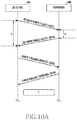
- FIG. 10A illustrates signals transmitted and received between the initiator 100 and the responder 200 for the range measurement operation between wireless devices according to an embodiment of the present invention.
- the signals illustrated in FIG. 10A merely corresponds to an example for describing the present invention and can be variously changed, and thus should not be interpreted to limit the scope of the present invention.
- the initiator 100 transmits a request range packet to the responder 200 in S 270 , and the responder 200 transmits a response range packet to the initiator 100 in S 275 .
- the initiator 100 and the responder 200 acquire Ti and Tr, respectively, by transmitting and receiving the range packets.
- the initiator 100 makes a request for Tr by transmitting a range feedback request illustrated in FIG. 10B to the responder 200 in S 280 , and the responder 200 carries Tr on a range feedback response illustrated in FIG. 10C and transmits the range feedback response to the initiator 100 in S 285 .
- Both the range feedback request and the range feedback response frame may be used as an action frame having a category that carries range information.
- the range feedback request and the range feedback response frame may be used as the range protection action frame. Otherwise, the range feedback request and the range feedback response frame may be used as the range action frame.
- the range feedback request illustrated in FIG. 10B is a packet transmitted by the initiator 100 for the purpose of making a request for Tr to the responder 200 .
- the range feedback request illustrated in FIG. 10B includes an action field 300 , a dialog token field 310 , and a request field 320 .
- the range feedback response illustrated in FIG. 10C is a packet which the responder 200 transmits to the initiator 100 in response to the range feedback request of the initiator 100 .
- the range feedback request illustrated in FIG. 10C includes an action field 400 , a dialog token field 410 , a time difference (TD) field 420 , and a time difference offset (TD offset) field 430 .
- the range feedback response may be used as a response thereto.
- FIGS. 10B and 10C Each of the fields in FIGS. 10B and 10C is defined as [Table 4] and [Table 5] below.
- Range feedback request or 0 range feedback request range feedback response 1: range feedback response Dialog Set an integer, which is not 0, to Token identify transmission and reception Request Whether a range feedback response 0: do not make request is requested 1: make request
- Range feedback request or 0 range feedback request range feedback response 1: range feedback response Dialog Write a value used for the Token range feedback request without any change, and set 0 when it is used as a response to the NDP TD Write Tr and Tor TD Offset Offset value of TD
- the range between the wireless devices is estimated by measuring the time during which the signal transmitted and received between the wireless devices of the wireless communication system is in the air.
- the circuit delay in the wireless devices includes a DAC delay, an ADC delay, a transmit circuit delay, and a receive circuit delay.
- A, B, D, E, and F correspond to range measurement errors.
- the range measurement error is an invariable constant (reference value)
- C can be easily acquired if the responder 200 transmits Tr to the initiator 100 and the initiator 100 calibrates the reference value.
- the range measurement may be inaccurate because A and E, that is, the DAC/ADC delay varies when power is newly supplied to the wireless device or the wireless device is reset. Accordingly, hereinafter, embodiments for measuring the range measurement error according to the circuit delay in the wireless devices and calibrating the range measurement error measured when the range between wireless devices is estimated will be proposed.
- FIG. 11 illustrates a connection configuration of a range error calibration module for the range measurement operation between wireless devices according to another embodiment of the present invention.
- the configuration illustrated in FIG. 11 merely corresponds to an example for describing the present invention and can be variously changed, and thus should not be interpreted to limit the scope of the present invention.
- the wireless device 100 includes the baseband processor 115 including the range error calibration module 112 , the DAC 125 A, the ADC 125 B, and the RF circuit/antenna 130 .
- the range error calibration module 112 for measuring and calibrating the range measurement error according to the circuit delay in the wireless device may be included in the range estimator 110 illustrated in FIGS. 1 to 3 or may be separated from the range estimator 110 .
- a predetermined signal is transmitted from the range error calibration module 112 of the baseband processor 115 . The determined signal returns to the range error calibration module 112 via the loopback circuit including the DAC 125 A, the RF circuit/antenna 130 , and the ADC 125 B.
- the determined signal may be a request range packet.
- the determined signal may be a predetermined signal.
- the determined signal may be one of a single tone signal, a sinewave signal, and a signal having a correlation characteristic.
- the range error calibration module 112 included in the initiator 100 is illustrated, the range error calibration module 112 may be configured within the responder 200 in the same form.
- the range error calibration may be performed when power of the wireless device is newly applied.
- the range error calibration may be performed when the wireless device is reset.
- the range error calibration may be performed every time before the range is measured as necessary.
- FIGS. 12A to 14 corresponds to an embodiment in which the internal circuit delay Toi of the initiator 100 , that is, the range measurement error is measured and the measured error is calibrated when the range is measured as the range error calibration module 112 of the initiator 100 illustrated in FIG. 11 generates and is looped back the range packet.
- the responder 200 may measure the internal circuit delay Tor in the same type.
- FIGS. 12A and 12B illustrate measurement of the internal circuit delay of the wireless device for the range measurement operation between the wireless devices according to another embodiment of the present invention.
- the initiator 100 performs a range calibration by the range error calibration module 112 illustrated in FIG. 11 and acquires Toi as a result of the range calibration.
- the responder 200 performs a range calibration by the range error compensation module and acquires Tor as a result of the range calibration
- FIG. 13 illustrates a processing flow of the range measurement operation between wireless devices according to another embodiment of the present invention.
- the processing flow is performed by the range estimator 110 and the range error calibration module 112 included in the baseband processor 115 of the initiator 100 .
- the flow illustrated in FIG. 13 merely corresponds to an example for describing the present invention and can be variously changed, and thus should not be interpreted to limit the scope of the present invention.
- the range error calibration module 112 of the initiator 100 calculates a time Toi from a time point when a request range packet is transmitted to a time point when the transmitted range packet is returned in step S 310 .
- the range packet is looped back after sequentially passing through the DAC 125 A, the RF circuit 130 , and the ADC 125 B as illustrated in FIG. 12A .
- the range error calibration module of the responder 200 may calculate a time Tor from a time point when a request range packet is transmitted to a time point when the transmitted range packet is returned.
- the range measurement error Toi may be calculated by the range estimator 110 instead of the range error calibration module 112 .
- Toi and Tor may be acquired from equation (4) below.
- step S 320 the range estimator 110 of the initiator 100 calculates the time Ti from the time point when the request range packet is transmitted to the responder 200 to a time point when reception of a response range packet is detected in response to the transmitted request range packet as illustrated in FIG. 8 .
- Equation (5) can be acquired by applying the range measurement errors Toi and Tor acquired from equation (4) to equation (2).
- step S 330 the range estimator 110 of the initiator 100 receives Tr and Tor from the responder 200 .
- Tr and Tor from the responder 200 may be received at the same time or at different time points.
- step S 340 the range estimator 110 of the initiator 100 calculates a propagation delay C between the initiator 100 and the responder 200 by applying the time Toi, Ti, Tr, and Tor acquired in steps S 310 to S 330 to equation (5).
- step S 350 the range estimator 110 of the initiator 100 estimates the range between the initiator 100 and the responder 200 by applying C calculated through equation (5) to equation (3).
- the accurate range measurement can be performed according to the above embodiment even though the internal circuit of the initiator 100 , for example, the DAC delay and the ADC delay are changed.
- FIG. 14 illustrates signals transmitted and received between the initiator 100 and the responder 200 for the range measurement operation between wireless devices according to another embodiment of the present invention.
- the signals illustrated in FIG. 14 merely corresponds to an example for describing the present invention and can be variously changed, and thus should not be interpreted to limit the scope of the present invention.
- the initiator 100 and the responder 200 measure range measurement errors Toi and Tor corresponding to internal circuit delays, respectively, in S 260 .
- the initiator 100 transmits a request range packet to the responder 200 in S 270
- the responder 200 transmits a response range packet to the initiator 100 in S 275 .
- the initiator 100 and the responder 200 acquire Ti and Tr, respectively, by transmitting and receiving the request/response range packets.
- Tr and Tor may be transmitted at the same time or separately.
- the range error calibration module 112 of the initiator 100 illustrated in FIG. 11 measures the internal circuit delay Toi of the initiator 100 , that is, the range measurement error by generating and looping back a predetermined signal, for example, a single tone signal, a sinewave signal, or a signal having a correlation characteristic, and stores the measured error in a memory (not shown). Amounts of change in A and E which are expected to be changed in the reference value of the range measurement error, that is, the change in the DAC/ADC delay are detected using the stored error value and the amounts of change are calibrated the range is measured.
- a predetermined signal for example, a single tone signal, a sinewave signal, or a signal having a correlation characteristic
- FIG. 15 illustrates a processing flow of the range measurement operation between wireless devices according to another embodiment of the present invention.
- the processing flow is performed by the range estimator 110 and the range error calibration module 112 included in the baseband processor 115 of the initiator 100 .
- the flow illustrated in FIG. 15 merely corresponds to an example for describing the present invention and can be variously changed, and thus should not be interpreted to limit the scope of the present invention.
- the range error calibration module 112 of the initiator 100 transmits a reference signal and stores a returned signal corresponding to the transmitted reference signal in a memory (not shown) in step S 410 .
- a sinewave signal, a single tone signal, or a signal having a correlation characteristic may be used as the reference signal.
- the reference signal is looped back after sequentially passing through the DAC 125 A, the RF circuit 130 , and the ADC 125 B as illustrated in FIG. 12A .
- the range error calibration module 112 calculates an amount of change in some elements in the range measurement error, for example, amounts of change in A and E by using the signal stored in the memory.
- the range error compensation module of the responder 200 transmits the reference signal, stores a returned signal corresponding to the transmitted reference signal in the memory, and then calculates an amount of change in some elements in the range measurement error, for example, amounts of change in A and E.
- the amounts of change in A and E in the range measurement error may be calculated by the range estimator 110 instead of the range error calibration module 112 .
- step S 420 the range estimator 110 of the initiator 100 calculates a time Ti from a time point when a request range packet is transmitted to the responder 200 to a time point when reception of a response range packet is detected in response to the transmitted request range packet as illustrated in FIG. 8 .
- step S 430 the range estimator 110 of the initiator 100 receives Tr from the responder 200 .
- the range estimator 110 of the initiator 100 may calculate a propagation delay C between the initiator 100 and the responder 200 in consideration of the amount of change in the range measurement error measured in step S 410 .
- the range estimator 110 may calculate the propagation delay C in consideration of the amounts of change in A and E by adding the amounts of change in A and E to the reference value in equation (2). Further, similar to FIG. 14 , the range may be measured by using the amount of change in A and E instead of Tor.
- step S 450 the range estimator 110 of the initiator 100 estimates the range between the initiator 100 and the responder 200 by applying C calculated through equation (5) to equation (3).
- FIG. 16 illustrates an operation for measuring an amount of change in an internal circuit delay of the initiator 100 for the range measurement operation between wireless devices according to another embodiment of the present invention.
- the operation illustrated in FIG. 16 merely corresponds to an example for describing the present invention and can be variously changed, and thus should not be interpreted to limit the scope of the present invention.
- the range error calibration module 112 of the initiator 100 transmits a reference signal and stores a returned signal corresponding to the transmitted reference signal in a memory (not shown). At this time, a sinewave signal, a single tone signal, or a signal having a correlation characteristic may be used as the reference signal.
- the reference signal is looped back after sequentially passing through the DAC 125 A, the RF circuit 130 , and the ADC 125 B as illustrated in FIG. 12A .
- the range error calibration module 112 calculates an amount of change in some elements in the range measurement error by using the signal stored in the memory.
- the range error calibration module 112 measures the range measurement error (A+B′+D′+E) by detecting a time point when the reference signal is looped back and returned from a time point when the reference signal is transmitted and stores the measured range measurement error in the memory.
- the range error calibration module 112 may calculate an amount of change in the range measurement error by comparing the previously stored range measurement error (A+B′+D′+E) and a newly stored range measurement error (A+B′+D′+E). At this time, if it is assumed that the amounts of change in B′ and D′ have no large difference, the amounts of change in A and E are calculated.
- the range error calibration module of the responder 200 transmits the reference signal, stores a returned signal corresponding to the transmitted reference signal in the memory, and then calculates an amount of change in some elements in the range measurement error, for example, amounts of change in A and E.
- FIG. 17 illustrates a configuration of connections between the range estimator 110 , and the ADC 125 B and the DAC 125 A for the range measurement operation between wireless devices without any error according to another embodiment of the present invention.
- the embodiment makes no change in a delay generated from the DAC 125 A and the ADC 125 B, thereby accurately measuring the range in spite of the range measurement based on the reference value in equation (2).
- the configuration illustrated in FIG. 17 merely corresponds to an example for describing the present invention and can be variously changed, and thus should not be interpreted to limit the scope of the present invention.
- the ADC delay may be generated in an interface between the ADC 125 B and the baseband processor 100
- the DAC delay may be generated in an interface between the DAC 125 A and the baseband processor 100 .
- Such delays result from FIFO (First Input First Output) between the ADC/DAC and the baseband processor 100 .
- FIFO First Input First Output
- the range estimator 110 operates from the clock of the ADC/DAC
- a change in the delay resulting from the FIFO may be removed. That is, the change in the delay of the ADC/DAC may be removed equally using the clock of the ADC/DAC and the range estimator 110 .
- the present invention it is possible to measure the range having the resolution of several cm through the exchange between signals through wireless devices in the wireless communication system. Further, according to embodiments of the present invention, it is possible to rapidly measure a range between wireless devices by using a request/response range packet. In addition, according to embodiments of the present invention, it is possible to provide the user with inaccuracy (reliability) of the range measurement which may be generated by an influence of a multi-path channel. Furthermore, according to embodiments of the present invention, it is possible to minimize power consumption of a range estimator by using signals used in the existing modem.
- the present invention has been described by the restricted embodiments and the drawings as described above, the present invention is not limited to the aforementioned embodiments, and various modifications and alterations can be made from the descriptions by those skilled in the art to which the present invention pertains.
- the wireless device is configured as illustrated in FIGS. 2 and 3 , operates according to the flow illustrated in FIGS. 4A, 4B, 4C, and 4D , and the range estimator of the wireless device measure the range according to the flow illustrated in FIG. 14
- the protection scope of the present invention is not necessarily limited thereto.
- the operations according to embodiments of the present invention may be implemented by a single processor.
- program instructions for performing various computer-implemented operations may be stored in a computer-readable medium.
- the computer readable medium may include a program command, a data file, a data structure, and the like independently or in combination.
- the program command may be things specially designed and configured for the present invention, or things that are well known to and can be used by those skilled in the related art.
- the computer readable recoding medium includes magnetic media such as a hard disk, a floppy disk, and a magnetic tape, optical media such as a CD-ROM and a DVD, magneto-optical media such as a floptical disk, and hardware devices such as a ROM, RAM, and a flash memory, which are specially constructed in such a manner that they can store and execute a program command.
- Examples of the program command include a machine language code generated by a compiler and a high-level language code executable by a computer through an interpreter and the like.
Applications Claiming Priority (3)
| Application Number | Priority Date | Filing Date | Title |
|---|---|---|---|
| KR10-2014-0020419 | 2014-02-21 | ||
| KR1020140020419A KR102246274B1 (ko) | 2014-02-21 | 2014-02-21 | 무선 통신시스템의 거리 측정을 위한 오차 보상 장치 및 방법 |
| PCT/KR2015/001557 WO2015126125A1 (ko) | 2014-02-21 | 2015-02-16 | 무선 통신시스템에서 거리 측정을 위한 오차 보상 장치 및 방법 |
Publications (2)
| Publication Number | Publication Date |
|---|---|
| US20170059701A1 US20170059701A1 (en) | 2017-03-02 |
| US10732275B2 true US10732275B2 (en) | 2020-08-04 |
Family
ID=53878565
Family Applications (1)
| Application Number | Title | Priority Date | Filing Date |
|---|---|---|---|
| US15/119,954 Active 2035-12-02 US10732275B2 (en) | 2014-02-21 | 2015-02-16 | Error compensation apparatus and method for measuring distance in wireless communication system |
Country Status (5)
| Country | Link |
|---|---|
| US (1) | US10732275B2 (ko) |
| EP (1) | EP3109665B1 (ko) |
| KR (1) | KR102246274B1 (ko) |
| CN (1) | CN106068464A (ko) |
| WO (1) | WO2015126125A1 (ko) |
Cited By (1)
| Publication number | Priority date | Publication date | Assignee | Title |
|---|---|---|---|---|
| US11057850B1 (en) * | 2019-06-10 | 2021-07-06 | Marvell Asia Pte, Ltd. | Transmit power control for null data packets |
Families Citing this family (17)
| Publication number | Priority date | Publication date | Assignee | Title |
|---|---|---|---|---|
| WO2016180952A1 (en) * | 2015-05-12 | 2016-11-17 | Decawave Ltd. | Asymmetric double-sided two-way ranging in an ultrawideband communication system |
| EP3926855A1 (en) * | 2016-03-11 | 2021-12-22 | Panasonic Intellectual Property Corporation of America | Wireless communication device |
| US10757675B2 (en) | 2016-06-03 | 2020-08-25 | Locix, Inc. | Systems and methods for precise radio frequency localization in the presence of multiple communication paths |
| US10470156B2 (en) * | 2016-06-03 | 2019-11-05 | Locix, Inc. | Systems and methods for coarse and fine time of flight estimates for precise radio frequency localization in the presence of multiple communication paths |
| US10440574B2 (en) * | 2016-06-12 | 2019-10-08 | Apple Inc. | Unlocking a device |
| US10455350B2 (en) | 2016-07-10 | 2019-10-22 | ZaiNar, Inc. | Method and system for radiolocation asset tracking via a mesh network |
| US10439712B2 (en) * | 2016-09-09 | 2019-10-08 | Huawei Technologies Co., Ltd. | System and methods for determining propagation delay |
| US10856167B2 (en) * | 2018-03-30 | 2020-12-01 | Intel Corporation | Enhanced multiple access point coordination |
| US10723317B2 (en) * | 2018-12-19 | 2020-07-28 | Fca Us Llc | Vehicle passive entry protocol with ultra wide band ranging |
| US10802104B2 (en) | 2018-12-26 | 2020-10-13 | Locix, Inc. | Systems and methods for using ranging and triangulation to determine locations of wireless sensor nodes based on radio frequency communications between the nodes and various RF-enabled devices |
| US10908274B2 (en) * | 2019-01-11 | 2021-02-02 | Samsung Electronics Co... Ltd. | Framework and methods to acknowledge the ranging configuration for IEEE 802.15.4Z |
| EP4099054B1 (en) * | 2020-02-25 | 2024-04-03 | Mitsubishi Electric Corporation | Wireless ranging system |
| US11297583B2 (en) * | 2020-03-03 | 2022-04-05 | Qualcomm Incorporated | Premium device-aided low-tier device group delay calibration for NR positioning |
| WO2021102480A2 (en) | 2020-03-10 | 2021-05-27 | Zeku, Inc. | Delay-line based transceiver calibration |
| KR20220012755A (ko) * | 2020-07-23 | 2022-02-04 | 삼성전자주식회사 | 통신 수행 방법 및 장치 |
| US11849468B2 (en) * | 2020-09-25 | 2023-12-19 | Apple Inc. | Many-to-many wireless network ranging technique |
| KR102300569B1 (ko) * | 2021-02-24 | 2021-09-09 | 단암시스템즈 주식회사 | 샘플 타이밍 오류 정보를 이용한 전파 지연 거리 측정 장치 및 방법 |
Citations (19)
| Publication number | Priority date | Publication date | Assignee | Title |
|---|---|---|---|---|
| EP0098160A1 (en) | 1982-06-29 | 1984-01-11 | Decca Limited | Method and apparatus for measuring distance |
| EP0139109A1 (de) | 1983-07-29 | 1985-05-02 | Alcatel N.V. | Einrichtung zum Ermitteln von Laufzeitschwankungen |
| US20020118723A1 (en) | 1999-08-02 | 2002-08-29 | Mccrady Dennis D. | Method and apparatus for determining the position of a mobile communication device using low accuracy clocks |
| US6876326B2 (en) * | 2001-04-23 | 2005-04-05 | Itt Manufacturing Enterprises, Inc. | Method and apparatus for high-accuracy position location using search mode ranging techniques |
| US20060012476A1 (en) | 2003-02-24 | 2006-01-19 | Russ Markhovsky | Method and system for finding |
| US20070099646A1 (en) | 2003-02-28 | 2007-05-03 | Sony Corporation | Ranging and positioning system, ranging and positioning method, and radio communication apparatus |
| CN101112112A (zh) | 2005-01-03 | 2008-01-23 | 法国电信公司 | 测量两个无线电通信装置之间的距离的方法和适于实现该方法的装置 |
| US7366243B1 (en) * | 2003-10-29 | 2008-04-29 | Itt Manufacturing Enterprises, Inc. | Methods and apparatus for transmitting non-contiguous spread spectrum signals for communications and navigation |
| KR20080050981A (ko) | 2006-12-04 | 2008-06-10 | 한국전자통신연구원 | 양방향 무선 전파 이동 시간을 이용한 거리 측정 방법 |
| CN101198163A (zh) | 2006-11-07 | 2008-06-11 | 法国电信公司 | 估算两个无线装置间距离的方法 |
| US20100128637A1 (en) | 2008-11-21 | 2010-05-27 | Qualcomm Incorporated | Network-centric determination of node processing delay |
| US20100177681A1 (en) * | 2009-01-09 | 2010-07-15 | Zafer Sahinoglu | Method and System for Target Positioning and Tracking in Cooperative Relay Networks |
| US20110148710A1 (en) * | 2009-12-23 | 2011-06-23 | Itrack, Llc | Distance separation tracking system |
| KR20110087602A (ko) | 2010-01-26 | 2011-08-03 | 인하대학교 산학협력단 | 클럭 오프셋을 이용한 거리 측정 방법 |
| US20110269478A1 (en) | 2010-04-30 | 2011-11-03 | Qualcomm Incorporated | Device for round trip time measurements |
| US20110292819A1 (en) | 2010-05-26 | 2011-12-01 | Qualcomm Incorporated | Two-way ranging messaging scheme |
| US20120269170A1 (en) | 2009-09-03 | 2012-10-25 | Qualcomm Atheros, Inc. | Synchronization-Free Station Locator In Wireless Network |
| KR20150026090A (ko) | 2013-08-30 | 2015-03-11 | 삼성전자주식회사 | 무선 통신시스템의 무선 기기 탐색 장치 및 방법 |
| KR20150052753A (ko) | 2013-11-06 | 2015-05-14 | 삼성전자주식회사 | 무선 통신시스템의 위치 추정 장치 및 방법 |
Family Cites Families (1)
| Publication number | Priority date | Publication date | Assignee | Title |
|---|---|---|---|---|
| US9125153B2 (en) * | 2008-11-25 | 2015-09-01 | Qualcomm Incorporated | Method and apparatus for two-way ranging |
-
2014
- 2014-02-21 KR KR1020140020419A patent/KR102246274B1/ko active IP Right Grant
-
2015
- 2015-02-16 US US15/119,954 patent/US10732275B2/en active Active
- 2015-02-16 CN CN201580011521.XA patent/CN106068464A/zh active Pending
- 2015-02-16 WO PCT/KR2015/001557 patent/WO2015126125A1/ko active Application Filing
- 2015-02-16 EP EP15752142.8A patent/EP3109665B1/en active Active
Patent Citations (27)
| Publication number | Priority date | Publication date | Assignee | Title |
|---|---|---|---|---|
| EP0098160A1 (en) | 1982-06-29 | 1984-01-11 | Decca Limited | Method and apparatus for measuring distance |
| EP0139109A1 (de) | 1983-07-29 | 1985-05-02 | Alcatel N.V. | Einrichtung zum Ermitteln von Laufzeitschwankungen |
| US4654810A (en) | 1983-07-29 | 1987-03-31 | International Standard Electric Corporation | Facility for determining delay variations |
| US20020118723A1 (en) | 1999-08-02 | 2002-08-29 | Mccrady Dennis D. | Method and apparatus for determining the position of a mobile communication device using low accuracy clocks |
| US6453168B1 (en) * | 1999-08-02 | 2002-09-17 | Itt Manufacturing Enterprises, Inc | Method and apparatus for determining the position of a mobile communication device using low accuracy clocks |
| US6801782B2 (en) * | 1999-08-02 | 2004-10-05 | Itt Manufacturing Enterprises, Inc. | Method and apparatus for determining the position of a mobile communication device |
| US6876326B2 (en) * | 2001-04-23 | 2005-04-05 | Itt Manufacturing Enterprises, Inc. | Method and apparatus for high-accuracy position location using search mode ranging techniques |
| US20060012476A1 (en) | 2003-02-24 | 2006-01-19 | Russ Markhovsky | Method and system for finding |
| US7822424B2 (en) * | 2003-02-24 | 2010-10-26 | Invisitrack, Inc. | Method and system for rangefinding using RFID and virtual triangulation |
| US20070099646A1 (en) | 2003-02-28 | 2007-05-03 | Sony Corporation | Ranging and positioning system, ranging and positioning method, and radio communication apparatus |
| US7366243B1 (en) * | 2003-10-29 | 2008-04-29 | Itt Manufacturing Enterprises, Inc. | Methods and apparatus for transmitting non-contiguous spread spectrum signals for communications and navigation |
| CN101112112A (zh) | 2005-01-03 | 2008-01-23 | 法国电信公司 | 测量两个无线电通信装置之间的距离的方法和适于实现该方法的装置 |
| US20090270042A1 (en) | 2005-01-03 | 2009-10-29 | Benoit Miscopein | Method of measuring a distance between two radio-communication devices and device adapted to implement one such method |
| CN101198163A (zh) | 2006-11-07 | 2008-06-11 | 法国电信公司 | 估算两个无线装置间距离的方法 |
| US20080146262A1 (en) | 2006-11-07 | 2008-06-19 | France Telecom | Method of estimating the distance between two radio equipments |
| KR20080050981A (ko) | 2006-12-04 | 2008-06-10 | 한국전자통신연구원 | 양방향 무선 전파 이동 시간을 이용한 거리 측정 방법 |
| US20100128637A1 (en) | 2008-11-21 | 2010-05-27 | Qualcomm Incorporated | Network-centric determination of node processing delay |
| US20100177681A1 (en) * | 2009-01-09 | 2010-07-15 | Zafer Sahinoglu | Method and System for Target Positioning and Tracking in Cooperative Relay Networks |
| US20120269170A1 (en) | 2009-09-03 | 2012-10-25 | Qualcomm Atheros, Inc. | Synchronization-Free Station Locator In Wireless Network |
| US20110148710A1 (en) * | 2009-12-23 | 2011-06-23 | Itrack, Llc | Distance separation tracking system |
| KR20110087602A (ko) | 2010-01-26 | 2011-08-03 | 인하대학교 산학협력단 | 클럭 오프셋을 이용한 거리 측정 방법 |
| US20110269478A1 (en) | 2010-04-30 | 2011-11-03 | Qualcomm Incorporated | Device for round trip time measurements |
| US20110292819A1 (en) | 2010-05-26 | 2011-12-01 | Qualcomm Incorporated | Two-way ranging messaging scheme |
| CN102906590A (zh) | 2010-05-26 | 2013-01-30 | 高通股份有限公司 | 双向测距消息方案 |
| KR20150026090A (ko) | 2013-08-30 | 2015-03-11 | 삼성전자주식회사 | 무선 통신시스템의 무선 기기 탐색 장치 및 방법 |
| US20160205501A1 (en) | 2013-08-30 | 2016-07-14 | Samsung Electronics Co., Ltd. | Wireless device searching apparatus and method in wireless communication system |
| KR20150052753A (ko) | 2013-11-06 | 2015-05-14 | 삼성전자주식회사 | 무선 통신시스템의 위치 추정 장치 및 방법 |
Non-Patent Citations (4)
| Title |
|---|
| Chinese Office Action dated Aug. 20, 2019, issued in the Chinese Application No. 201580011521.X. |
| Chinese Office Action dated Jan. 29, 2019, issued in the Chinese Application No. 201580011521.X. |
| Indian Office Action dated May 1, 2020, issued in Indian Patent Application No. 201637031946. |
| Korean Office Action dated May 11, 2020, issued in Korean Patent Application No. 10-2014-0020419. |
Cited By (1)
| Publication number | Priority date | Publication date | Assignee | Title |
|---|---|---|---|---|
| US11057850B1 (en) * | 2019-06-10 | 2021-07-06 | Marvell Asia Pte, Ltd. | Transmit power control for null data packets |
Also Published As
| Publication number | Publication date |
|---|---|
| CN106068464A (zh) | 2016-11-02 |
| KR20150098985A (ko) | 2015-08-31 |
| EP3109665A1 (en) | 2016-12-28 |
| WO2015126125A1 (ko) | 2015-08-27 |
| US20170059701A1 (en) | 2017-03-02 |
| KR102246274B1 (ko) | 2021-04-29 |
| EP3109665B1 (en) | 2024-04-17 |
| EP3109665A4 (en) | 2018-01-24 |
Similar Documents
| Publication | Publication Date | Title |
|---|---|---|
| US10732275B2 (en) | Error compensation apparatus and method for measuring distance in wireless communication system | |
| US10353048B2 (en) | Apparatus and method for location estimation in a wireless communication system | |
| KR101563572B1 (ko) | 무선 네트워크 환경에서 측정치들 및 정보 수집 | |
| CN107430190B (zh) | 使用广播消息的位置和范围确定 | |
| US9226260B2 (en) | Initiator-conditioned fine timing measurement service request | |
| US9213093B2 (en) | Pairwise measurements for improved position determination | |
| US8509819B2 (en) | Information processing apparatus and correction method | |
| US9551775B2 (en) | Enhancing client location via beacon detection | |
| US20150373503A1 (en) | Method and apparatus for positioning system enhancement with visible light communication | |
| US9980097B2 (en) | Method and apparatus for indoor location estimation among peer-to-peer devices | |
| US9794906B1 (en) | Double sided round trip time calibration | |
| JP2016028506A (ja) | ラウンドトリップタイム測定のためのデバイス | |
| JP2007218614A (ja) | 位置推定方法及び位置推定システム | |
| JP2013513786A (ja) | 非同期ネットワーク局のクロックのずれを補正するための補正因子の計算を用いたtdoaに基づく位置測定方法 | |
| US20160337808A1 (en) | Method and Apparatus for Indoor Location Estimation Among Peer-To-Peer Devices | |
| US20160109554A1 (en) | ADAPTIVE OPTIMIZATION OF TIME OF FLIGHT (ToF) EXCHANGE | |
| EP3348099A1 (en) | Fingerprint positioning for mobile terminals | |
| CN108023682B (zh) | 一种定位方法及定位装置 | |
| US20160061931A1 (en) | Estimation system and reception node | |
| CN109196926A (zh) | 用于估计周转校准因子的组合精细定时测量(ftm)和非ftm消息传送 | |
| JP2012034002A (ja) | シミュレーションシステム、シミュレーション装置およびシミュレーション方法 | |
| JP2015507172A (ja) | 距離推定 | |
| US20230413221A1 (en) | Method and system for improved positioning measurement | |
| JP2023124488A (ja) | 通信品質推定装置、通信品質推定方法、プログラム |
Legal Events
| Date | Code | Title | Description |
|---|---|---|---|
| AS | Assignment |
Owner name: SAMSUNG ELECTRONICS CO., LTD., KOREA, REPUBLIC OF Free format text: ASSIGNMENT OF ASSIGNORS INTEREST;ASSIGNORS:OH, JONG-HO;KIM, JAE-HWA;YOON, JUNG-MIN;AND OTHERS;SIGNING DATES FROM 20160718 TO 20160728;REEL/FRAME:039477/0106 |
|
| STPP | Information on status: patent application and granting procedure in general |
Free format text: ADVISORY ACTION MAILED |
|
| STPP | Information on status: patent application and granting procedure in general |
Free format text: DOCKETED NEW CASE - READY FOR EXAMINATION |
|
| STPP | Information on status: patent application and granting procedure in general |
Free format text: NON FINAL ACTION MAILED |
|
| STPP | Information on status: patent application and granting procedure in general |
Free format text: FINAL REJECTION MAILED |
|
| STPP | Information on status: patent application and granting procedure in general |
Free format text: ADVISORY ACTION MAILED |
|
| STPP | Information on status: patent application and granting procedure in general |
Free format text: DOCKETED NEW CASE - READY FOR EXAMINATION |
|
| STPP | Information on status: patent application and granting procedure in general |
Free format text: NON FINAL ACTION MAILED |
|
| STPP | Information on status: patent application and granting procedure in general |
Free format text: NOTICE OF ALLOWANCE MAILED -- APPLICATION RECEIVED IN OFFICE OF PUBLICATIONS |
|
| STPP | Information on status: patent application and granting procedure in general |
Free format text: PUBLICATIONS -- ISSUE FEE PAYMENT VERIFIED |
|
| STCF | Information on status: patent grant |
Free format text: PATENTED CASE |
|
| FEPP | Fee payment procedure |
Free format text: MAINTENANCE FEE REMINDER MAILED (ORIGINAL EVENT CODE: REM.); ENTITY STATUS OF PATENT OWNER: LARGE ENTITY |