US10731917B1 - Refrigerator appliance with articulating drawer front - Google Patents
Refrigerator appliance with articulating drawer front Download PDFInfo
- Publication number
- US10731917B1 US10731917B1 US16/564,227 US201916564227A US10731917B1 US 10731917 B1 US10731917 B1 US 10731917B1 US 201916564227 A US201916564227 A US 201916564227A US 10731917 B1 US10731917 B1 US 10731917B1
- Authority
- US
- United States
- Prior art keywords
- bar
- drawer
- door
- refrigerator appliance
- drawer body
- Prior art date
- Legal status (The legal status is an assumption and is not a legal conclusion. Google has not performed a legal analysis and makes no representation as to the accuracy of the status listed.)
- Active - Reinstated
Links
Images


Classifications
-
- A—HUMAN NECESSITIES
- A47—FURNITURE; DOMESTIC ARTICLES OR APPLIANCES; COFFEE MILLS; SPICE MILLS; SUCTION CLEANERS IN GENERAL
- A47B—TABLES; DESKS; OFFICE FURNITURE; CABINETS; DRAWERS; GENERAL DETAILS OF FURNITURE
- A47B88/00—Drawers for tables, cabinets or like furniture; Guides for drawers
- A47B88/90—Constructional details of drawers
- A47B88/944—Drawers characterised by the front panel
- A47B88/95—Drawers characterised by the front panel characterised by connection means for the front panel
-
- A—HUMAN NECESSITIES
- A47—FURNITURE; DOMESTIC ARTICLES OR APPLIANCES; COFFEE MILLS; SPICE MILLS; SUCTION CLEANERS IN GENERAL
- A47B—TABLES; DESKS; OFFICE FURNITURE; CABINETS; DRAWERS; GENERAL DETAILS OF FURNITURE
- A47B88/00—Drawers for tables, cabinets or like furniture; Guides for drawers
- A47B88/90—Constructional details of drawers
- A47B88/944—Drawers characterised by the front panel
-
- F—MECHANICAL ENGINEERING; LIGHTING; HEATING; WEAPONS; BLASTING
- F25—REFRIGERATION OR COOLING; COMBINED HEATING AND REFRIGERATION SYSTEMS; HEAT PUMP SYSTEMS; MANUFACTURE OR STORAGE OF ICE; LIQUEFACTION SOLIDIFICATION OF GASES
- F25D—REFRIGERATORS; COLD ROOMS; ICE-BOXES; COOLING OR FREEZING APPARATUS NOT OTHERWISE PROVIDED FOR
- F25D23/00—General constructional features
- F25D23/02—Doors; Covers
- F25D23/021—Sliding doors
-
- F—MECHANICAL ENGINEERING; LIGHTING; HEATING; WEAPONS; BLASTING
- F25—REFRIGERATION OR COOLING; COMBINED HEATING AND REFRIGERATION SYSTEMS; HEAT PUMP SYSTEMS; MANUFACTURE OR STORAGE OF ICE; LIQUEFACTION SOLIDIFICATION OF GASES
- F25D—REFRIGERATORS; COLD ROOMS; ICE-BOXES; COOLING OR FREEZING APPARATUS NOT OTHERWISE PROVIDED FOR
- F25D23/00—General constructional features
- F25D23/02—Doors; Covers
- F25D23/028—Details
-
- F—MECHANICAL ENGINEERING; LIGHTING; HEATING; WEAPONS; BLASTING
- F25—REFRIGERATION OR COOLING; COMBINED HEATING AND REFRIGERATION SYSTEMS; HEAT PUMP SYSTEMS; MANUFACTURE OR STORAGE OF ICE; LIQUEFACTION SOLIDIFICATION OF GASES
- F25D—REFRIGERATORS; COLD ROOMS; ICE-BOXES; COOLING OR FREEZING APPARATUS NOT OTHERWISE PROVIDED FOR
- F25D25/00—Charging, supporting, and discharging the articles to be cooled
- F25D25/02—Charging, supporting, and discharging the articles to be cooled by shelves
- F25D25/024—Slidable shelves
- F25D25/025—Drawers
-
- A—HUMAN NECESSITIES
- A47—FURNITURE; DOMESTIC ARTICLES OR APPLIANCES; COFFEE MILLS; SPICE MILLS; SUCTION CLEANERS IN GENERAL
- A47B—TABLES; DESKS; OFFICE FURNITURE; CABINETS; DRAWERS; GENERAL DETAILS OF FURNITURE
- A47B2210/00—General construction of drawers, guides and guide devices
- A47B2210/17—Drawers used in connection with household appliances
- A47B2210/175—Refrigerators or freezers
Definitions
- the present disclosure relates generally to refrigerator appliances, and more particularly to refrigerator appliances which include a drawer having a tilt out drawer front feature.
- Refrigerator appliances generally include a cabinet that defines chilled chambers for receipt of food items for storage.
- One or more insulated, sealing doors are provided for selectively enclosing the chilled food storage chambers.
- Consumers generally prefer chilled chambers that facilitate visibility and accessibility of food items stored therein.
- the fresh food chamber is positioned next to the freezer chamber within the cabinet.
- Such a configuration can permit easy access to food items stored on doors of the refrigerator appliances.
- the cabinet can be deep and narrow such that accessing food items at a back of the fresh food chamber and/or freezer chamber is difficult.
- the freezer chamber is positioned either above or below the fresh food chamber in the cabinet, which are commonly referred to as top mount or bottom mount refrigerator appliances.
- Such a configuration can provide a relatively wide fresh food chamber and/or freezer chamber, e.g., as compared to the side-by-side configuration.
- the depth of the fresh food chamber and the freezer chamber can make accessing food items at a back of the refrigerator appliance difficult.
- a refrigerator appliance with features for assisting with accessing food items stored therein would be useful.
- a refrigerator appliance in accordance with one embodiment, includes a cabinet defining a fresh food storage chamber and a frozen food storage chamber and a drawer slidably mounted within one of the fresh food storage chamber and the frozen food storage chamber.
- the drawer includes a drawer body defining an interior of the drawer and a door attached to the drawer body via a linkage such that the door is movable relative to the drawer body between a closed position where the door encloses the interior of the drawer and an open position to provide access to the interior of the drawer.
- a drawer for a refrigerator appliance includes a cabinet defining a fresh food storage chamber and a frozen food storage chamber.
- the drawer is slidably mountable within one of the fresh food storage chamber and the frozen food storage chamber.
- the drawer includes a drawer body defining an interior of the drawer and a door attached to the drawer body via a linkage such that the door is movable relative to the drawer body between a closed position where the door encloses the interior of the drawer and an open position to provide access to the interior of the drawer.
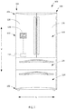
- FIG. 1 provides a front view of a refrigerator appliance according to one or more exemplary embodiments of the present subject matter.
- FIG. 2 provides a perspective view of the refrigerator appliance of FIG. 1 with a drawer thereof in an extended position and a door of the drawer in a closed position.
- FIG. 3 provides a perspective view of the refrigerator appliance of FIG. 2 with the door of the drawer in an open position.
- FIG. 4 provides a perspective view of the drawer of FIG. 2 .
- FIG. 5 provides a perspective view of the drawer of FIG. 2 with the door of the drawer in an intermediate position.
- FIG. 6 provides a perspective view of the drawer of FIG. 2 with the door of the drawer in the open position.
- FIG. 7 provides a side view of the drawer of FIG. 2 .
- FIG. 8 provides a side view of the drawer of FIG. 2 with the door of the drawer in the open position.
- FIG. 9 provides an enlarged perspective view of a portion of a drawer body of the drawer of FIG. 2 .
- the terms “first,” “second,” and “third” may be used interchangeably to distinguish one component from another and are not intended to signify location or importance of the individual components.
- Terms such as “inner” and “outer” refer to relative directions with respect to the interior and exterior of the refrigerator appliance, and in particular the food storage chamber(s) defined therein. For example, “inner” or “inward” refers to the direction towards the interior of the refrigerator appliance.
- Terms such as “left,” “right,” “front,” “back,” “top,” or “bottom” are used with reference to the perspective of a user accessing the refrigerator appliance. For example, a user stands in front of the refrigerator to open the doors and reaches into the food storage chamber(s) to access items therein.
- terms of approximation such as “generally,” “about,” or “approximately” include values within ten percent greater or less than the stated value.
- such terms include within ten degrees greater or less than the stated angle or direction, e.g., “generally vertical” includes forming an angle of up to ten degrees either clockwise or counterclockwise with the vertical direction V.
- FIG. 1 is a front view of an exemplary embodiment of a refrigerator appliance 100 .
- FIG. 2 is a perspective view of the refrigerator appliance 100 having a drawer 125 in an open position to reveal the interior 126 of the drawer 125 .
- FIG. 3 is a perspective view of the refrigerator appliance 100 having a door 132 of the drawer 125 in an open position to promote access to the interior 126 of the drawer 125 .
- Refrigerator appliance 100 extends between a top 101 and a bottom 102 along a vertical direction V.
- Refrigerator appliance 100 also extends between a left side 105 and a right side 106 along a lateral direction L.
- a transverse direction T may additionally be defined perpendicular to the vertical and lateral directions V, L.
- Refrigerator appliance 100 extends along the transverse direction T between a front portion 108 and a back portion 110 .
- Refrigerator appliance 100 includes a cabinet or housing 120 defining an upper fresh food chamber 122 and a lower freezer chamber or frozen food storage chamber 124 arranged below the fresh food chamber 122 along the vertical direction V. Because the frozen food storage chamber 124 is positioned below the fresh food storage chamber 122 , refrigerator appliance 100 is generally referred to as a bottom mount refrigerator. Using the teachings disclosed herein, one of skill in the art will understand that the present technology can be used with other types of refrigerators (e.g., side-by-sides) or a freezer appliance as well. Consequently, the description set forth herein is for illustrative purposes only and is not intended to limit the invention in any aspect.
- Refrigerator doors 128 are rotatably hinged to an edge of housing 120 for accessing fresh food chamber 122 . It should be noted that while two doors 128 in a “French door” configuration are illustrated, any suitable arrangement of doors utilizing one, two or more doors is within the scope and spirit of the present disclosure.
- a freezer door 130 is arranged below refrigerator doors 128 for accessing freezer chamber 124 . In the exemplary embodiment, freezer door 130 is coupled to a freezer drawer (not shown) slidably coupled within freezer chamber 124 .
- Operation of the refrigerator appliance 100 can be regulated by a controller 134 that is operatively coupled to a user interface panel 136 .
- Panel 136 provides selections for user manipulation of the operation of refrigerator appliance 100 such as e.g., temperature selections.
- the controller 134 operates various components of the refrigerator appliance 100 .
- the controller may include a memory and one or more microprocessors, CPUs or the like, such as general or special purpose microprocessors operable to execute programming instructions or micro-control code associated with operation of refrigerator appliance 100 .
- the memory may represent random access memory such as DRAM, or read only memory such as ROM or FLASH.
- the processor executes programming instructions stored in memory.
- the memory may be a separate component from the processor or may be included onboard within the processor.
- the controller 134 may be positioned in a variety of locations throughout refrigerator appliance 100 . In the illustrated embodiment, the controller 134 may be located within one of the doors 128 . In such an embodiment, input/output (“I/O”) signals may be routed between the controller and various operational components of refrigerator appliance 100 .
- the user interface panel 136 may represent a general purpose I/O (“GPIO”) device or functional block.
- the user interface 136 may include input components, such as one or more of a variety of electrical, mechanical or electro-mechanical input devices including rotary dials, push buttons, and touch pads.
- the user interface 136 may include a display component, such as a digital or analog display device designed to provide operational feedback to a user.
- the user interface 136 may be in communication with the controller 134 via one or more signal lines or shared communication busses.
- FIGS. 2 and 3 illustrate one example embodiment of a drawer 125 for the refrigerator appliance 100 .
- the drawer 125 may be slidably mounted within the cabinet 120 , e.g., with slides 138 .
- the drawer 125 may thereby be slidable between a retracted (e.g., closed) position where the door 132 of the drawer 125 is proximate the cabinet 120 , e.g., the door 132 may be sealingly engaged with the cabinet 120 by gaskets 156 ( FIG. 4 ) when in the retracted position, and an extended (e.g., open) position where the door 132 of the drawer 125 is spaced apart from the cabinet 120 .
- a retracted e.g., closed
- the door 132 may be sealingly engaged with the cabinet 120 by gaskets 156 ( FIG. 4 ) when in the retracted position
- an extended (e.g., open) position where the door 132 of the drawer 125 is spaced apart from the cabinet 120
- the drawer 125 may be an internal drawer without gaskets 156 and the door 132 of the drawer 125 may be proximate the front portion 108 of the cabinet 120 while the door 132 and the remainder of the drawer 125 are fully inside the cabinet 120 in the retracted position.
- the drawer 125 is a freezer drawer slidably mounted within the frozen food storage chamber 124 of the refrigerator appliance 100 . Accordingly, the drawer 125 may assist with storing and providing access to frozen food items.
- smaller food items such as a bag of frozen vegetables may be stored in the freezer drawer 125 to prevent or reduce such items from being obscured under or behind larger items such as a frozen turkey, etc., as compared to when only a single portion of the refrigerator appliance 100 is provided for storing frozen items.
- the drawer 125 may be slidably mounted within the fresh food storage chamber 122 and may provide similar advantages with respect to storing and accessing fresh food items.
- the drawer 125 may have a tilt out drawer front, e.g., the door 132 of the drawer 125 may be connected to a drawer body 146 with a linkage 140 comprising a plurality of bars 142 interconnected by pivot joints such that the door 132 is movable, e.g., articulable and/or rotatable, relative to the drawer body 146 , e.g., between a closed position ( FIG. 2 ) and an open position ( FIG. 3 ).
- a tilt out drawer front e.g., the door 132 of the drawer 125 may be connected to a drawer body 146 with a linkage 140 comprising a plurality of bars 142 interconnected by pivot joints such that the door 132 is movable, e.g., articulable and/or rotatable, relative to the drawer body 146 , e.g., between a closed position ( FIG. 2 ) and an open position ( FIG. 3 ).
- the drawer 125 may include a drawer body 146 which includes a left wall 148 , a back wall 150 , a right wall 152 , and a floor 154 .
- the drawer body 146 at least partially defines an interior 126 of the drawer 125 which may provide a storage volume, e.g., for food items.
- the interior 126 of the drawer 125 is collectively defined by the drawer body 146 and the door 132 .
- the door 132 of the drawer 125 may be movable relative to the drawer body 146 , to an open position as shown in FIG. 3 .
- the door 132 may be movable relative to the drawer body 146 in that the door 132 may be connected to the drawer body 146 by one or more linkages 140 .
- the door 132 may be connected to the drawer body 146 by a pair of linkages 140 , such as a left linkage 140 including one or more bars 142 connecting the left side wall 148 of the drawer body 146 to the door 132 and a right linkage 140 including one or more bars 142 connecting the right side wall 152 of the drawer body 146 to the door 132 .
- a pair of linkages 140 such as a left linkage 140 including one or more bars 142 connecting the left side wall 148 of the drawer body 146 to the door 132 and a right linkage 140 including one or more bars 142 connecting the right side wall 152 of the drawer body 146 to the door 132 .
- the drawer 125 may be slidably mounted within the cabinet 120 , e.g., within one of the fresh food storage 122 chamber and the frozen food storage chamber 124 , by a left slide 138 on the left side wall 148 and a right slide 138 on the right side wall 152 , such that the drawer 125 can slide between the retracted position of the drawer 125 ( FIG. 1 ) and the extended position of the drawer 125 ( FIGS. 2 and 3 ).
- one or more gaskets 156 FIG. 4
- the linkages 140 may each be connected to a corresponding slide 138 at each side wall of the drawer body 146 .
- the linkage 140 may be a four bar linkage comprising, e.g., consisting of, four bars.
- the four bars may include a first bar 200 , a second bar 206 , a third bar 212 , and a fourth bar 218 .
- the first bar 200 may be connected to a side wall of the drawer body 146 , e.g., to one of the left side wall 148 and the right side wall 152 .
- the second bar 206 may be connected to the side wall (e.g., the same one of the side walls 148 and 152 to which the first bar 200 is connected) of the drawer body 146 .
- the third bar 212 may be connected to the first bar 200 , to the second bar 206 , and to an inner surface 144 ( FIGS. 5 and 6 ) of the door 132 .
- the fourth bar 218 may be connected to the first bar 200 and to the inner surface 144 of the door 132 .
- the plurality of bars of the linkage 140 may be connected by pivot joints.
- the first bar 200 may be connected to the side wall 148 or 152 at a first end 202 of the first bar 200 by a first pivot joint 250 and the second bar 206 may be connected to the side wall 148 or 152 at a first end 208 of the second bar 206 by a second pivot joint 252 .
- the first pivot joint 250 and the second pivot joint 252 may be aligned along the vertical direction V.
- the first bar 200 may be connected to a first end 220 of the fourth bar 218 at a second end 204 of the first bar 200 opposite the first end 202 of the first bar 200 by a third pivot joint 254 .
- the fourth bar 218 may be connected to the inner surface 144 of the door 132 , such as a mounting bar 226 on the inner surface 144 , at a second end 224 of the fourth bar 218 opposite the first end 220 of the fourth bar 218 by a fourth pivot joint 256 .
- the third bar 212 may be connected, at a first end 214 thereof, to an intermediate point 203 of the first bar 200 between the first end 202 and the second end 204 of the first bar 200 by a fifth pivot joint 258 .
- a second end 210 of the second bar 206 may be connected to the third bar 212 at an intermediate point 215 of the third bar 212 by a sixth pivot joint 260 .
- the intermediate point 215 of the third bar 212 may be between the first end 214 of the third bar 212 and a second end 216 of the third bar 212 opposite the first end 214 of the third bar 212 .
- the second end 216 of the third bar 212 may be connected to the inner surface 144 of the door 132 , e.g., to the mounting bar 226 thereon, by a seventh pivot joint 262 .
- the drawer 125 disclosed herein, in particular the door 132 and the linkage 140 which connects the drawer 125 to the drawer body 146 may provide several advantageous features, examples of which may be appreciated with respect to FIGS. 7 and 8 and the following description.
- the linkage 140 may permit the door 132 to move relative to the drawer body 146 such that the inner surface 144 of the door 132 is parallel to, and in at least some embodiments, colinear or coplanar with, the floor 154 of the drawer 125 when the door 132 is in the open position ( FIG. 8 ).
- Such alignment of the inner surface 144 of the door 132 with the floor 154 of the drawer 125 may advantageously promote ease of access to items stored within the interior 126 of the drawer 125 .
- the linkage 140 may provide extended useful life of the gasket 156 .
- the linkage 140 may permit the door 132 to move relative to the drawer body 146 between the closed position ( FIG. 7 ) and the open position ( FIG. 8 ) such that the door 132 is offset from the drawer body 146 through the range of motion from the closed position to the open position, and vice versa.
- the gasket 156 may clear the drawer body 146 while the door 132 moves to the open position and when the door 132 is in the open position, as well as from the open position to the closed position. Accordingly, rubbing of the gasket 156 on the drawer body 146 and concomitant wear on the gasket 156 when moving between the open and closed positions may be reduced or avoided.
- the use of the linkage 140 to connect the door 132 to the drawer body 146 may provide a controlled gap between the door 132 , e.g., the inner surface 144 thereof, and the drawer body 146 when the door 132 is in the open position, e.g., the lengths of the bars making up the linkage 140 may be selected to provide a short distance for items being slid into or out of the drawer 125 to span while also providing a large enough gap that the gasket 156 clears the drawer body 146 , as described.
- the foregoing advantages are examples only and are not limiting, e.g., embodiments of the present disclose may also provide additional advantages as will be recognized by those of ordinary skill in the art.
- the drawer 125 may include a first concealing wall 180 and a second concealing wall 182 which extend from the side wall 148 or 152 and to or towards the door 132 .
- the linkage 140 may be positioned between the concealing walls 180 and 182 .
- the concealing walls 180 and 182 may advantageously improve the aesthetics of the drawer 125 by hiding the linkage 140 .
- the concealing walls 180 and 182 may prevent objects, e.g., smaller food items, from imposing into the linkage 140 , such as between the bars thereof, and interfering with movement of the door 132 between the open position and the closed position.
Landscapes
- Engineering & Computer Science (AREA)
- Chemical & Material Sciences (AREA)
- Combustion & Propulsion (AREA)
- Physics & Mathematics (AREA)
- Mechanical Engineering (AREA)
- Thermal Sciences (AREA)
- General Engineering & Computer Science (AREA)
- Refrigerator Housings (AREA)
Abstract
Description
Claims (14)
Priority Applications (1)
| Application Number | Priority Date | Filing Date | Title |
|---|---|---|---|
| US16/564,227 US10731917B1 (en) | 2019-09-09 | 2019-09-09 | Refrigerator appliance with articulating drawer front |
Applications Claiming Priority (1)
| Application Number | Priority Date | Filing Date | Title |
|---|---|---|---|
| US16/564,227 US10731917B1 (en) | 2019-09-09 | 2019-09-09 | Refrigerator appliance with articulating drawer front |
Publications (1)
| Publication Number | Publication Date |
|---|---|
| US10731917B1 true US10731917B1 (en) | 2020-08-04 |
Family
ID=71838729
Family Applications (1)
| Application Number | Title | Priority Date | Filing Date |
|---|---|---|---|
| US16/564,227 Active - Reinstated US10731917B1 (en) | 2019-09-09 | 2019-09-09 | Refrigerator appliance with articulating drawer front |
Country Status (1)
| Country | Link |
|---|---|
| US (1) | US10731917B1 (en) |
Cited By (4)
| Publication number | Priority date | Publication date | Assignee | Title |
|---|---|---|---|---|
| US11317717B1 (en) * | 2020-11-04 | 2022-05-03 | Haier Us Appliance Solutions, Inc. | Tilt front drawer with locking slide |
| CN114777402A (en) * | 2022-04-25 | 2022-07-22 | 珠海格力电器股份有限公司 | Cover plate structure, refrigerator drawer, refrigerator and control method |
| US20240041208A1 (en) * | 2022-08-02 | 2024-02-08 | Haier Us Appliance Solutions, Inc. | Powered tilt drawer front for a domestic appliance |
| US20240102725A1 (en) * | 2022-09-23 | 2024-03-28 | Haier Us Appliance Solutions, Inc. | Synchronized basket flap |
Citations (13)
| Publication number | Priority date | Publication date | Assignee | Title |
|---|---|---|---|---|
| US4654930A (en) | 1985-04-22 | 1987-04-07 | Karl Lautenschlager Gmbh & Co. Kg | Self-closing over-center hinge having a link guided in a spring biased cam |
| US6243918B1 (en) * | 1994-12-16 | 2001-06-12 | T.G.N. S.P.A. | Snap hinge |
| KR20050005786A (en) * | 2003-06-30 | 2005-01-14 | 소니 가부시끼 가이샤 | Device registration system, device registration server, device registration method, device registration program, storage medium, and terminal device |
| KR20050057863A (en) * | 2003-12-11 | 2005-06-16 | 장명택 | Articulated hinge assembly |
| US7591516B2 (en) | 2002-04-03 | 2009-09-22 | Lg Electronics Inc. | Door apparatus for drawer type refrigerator |
| US20100090575A1 (en) * | 2008-10-15 | 2010-04-15 | Jose Uthuppan | Refrigerator with easy access drawer |
| US7886407B2 (en) * | 2005-04-26 | 2011-02-15 | Suspa Gmbh | Hinge arrangement |
| US7987558B2 (en) * | 2005-02-02 | 2011-08-02 | Hettich-Oni GmbH & Co. | Multilink hinge |
| EP2754982A1 (en) * | 2013-01-11 | 2014-07-16 | Electrolux Home Products Corporation N.V. | Refrigerating appliance |
| US8955352B2 (en) * | 2009-05-12 | 2015-02-17 | Lg Electronics Inc. | Refrigerator |
| JP2017020718A (en) * | 2015-07-10 | 2017-01-26 | シャープ株式会社 | Drawer device for refrigerator |
| WO2018075094A1 (en) | 2016-10-17 | 2018-04-26 | Whirlpool Corporation | Hinge assembly |
| CN108868422A (en) * | 2018-06-30 | 2018-11-23 | 江苏星徽精密科技有限公司 | A kind of built-in refrigerator buffer hinge without hovering |
-
2019
- 2019-09-09 US US16/564,227 patent/US10731917B1/en active Active - Reinstated
Patent Citations (13)
| Publication number | Priority date | Publication date | Assignee | Title |
|---|---|---|---|---|
| US4654930A (en) | 1985-04-22 | 1987-04-07 | Karl Lautenschlager Gmbh & Co. Kg | Self-closing over-center hinge having a link guided in a spring biased cam |
| US6243918B1 (en) * | 1994-12-16 | 2001-06-12 | T.G.N. S.P.A. | Snap hinge |
| US7591516B2 (en) | 2002-04-03 | 2009-09-22 | Lg Electronics Inc. | Door apparatus for drawer type refrigerator |
| KR20050005786A (en) * | 2003-06-30 | 2005-01-14 | 소니 가부시끼 가이샤 | Device registration system, device registration server, device registration method, device registration program, storage medium, and terminal device |
| KR20050057863A (en) * | 2003-12-11 | 2005-06-16 | 장명택 | Articulated hinge assembly |
| US7987558B2 (en) * | 2005-02-02 | 2011-08-02 | Hettich-Oni GmbH & Co. | Multilink hinge |
| US7886407B2 (en) * | 2005-04-26 | 2011-02-15 | Suspa Gmbh | Hinge arrangement |
| US20100090575A1 (en) * | 2008-10-15 | 2010-04-15 | Jose Uthuppan | Refrigerator with easy access drawer |
| US8955352B2 (en) * | 2009-05-12 | 2015-02-17 | Lg Electronics Inc. | Refrigerator |
| EP2754982A1 (en) * | 2013-01-11 | 2014-07-16 | Electrolux Home Products Corporation N.V. | Refrigerating appliance |
| JP2017020718A (en) * | 2015-07-10 | 2017-01-26 | シャープ株式会社 | Drawer device for refrigerator |
| WO2018075094A1 (en) | 2016-10-17 | 2018-04-26 | Whirlpool Corporation | Hinge assembly |
| CN108868422A (en) * | 2018-06-30 | 2018-11-23 | 江苏星徽精密科技有限公司 | A kind of built-in refrigerator buffer hinge without hovering |
Cited By (8)
| Publication number | Priority date | Publication date | Assignee | Title |
|---|---|---|---|---|
| US11317717B1 (en) * | 2020-11-04 | 2022-05-03 | Haier Us Appliance Solutions, Inc. | Tilt front drawer with locking slide |
| US20220133037A1 (en) * | 2020-11-04 | 2022-05-05 | Haier Us Appliance Solutions, Inc. | Tilt front drawer with locking slide |
| CN114777402A (en) * | 2022-04-25 | 2022-07-22 | 珠海格力电器股份有限公司 | Cover plate structure, refrigerator drawer, refrigerator and control method |
| CN114777402B (en) * | 2022-04-25 | 2024-05-28 | 珠海格力电器股份有限公司 | Cover plate structure, refrigerator drawer, refrigerator and control method |
| US20240041208A1 (en) * | 2022-08-02 | 2024-02-08 | Haier Us Appliance Solutions, Inc. | Powered tilt drawer front for a domestic appliance |
| US11986091B2 (en) * | 2022-08-02 | 2024-05-21 | Haier Us Appliance Solutions, Inc. | Powered tilt drawer front for a domestic appliance |
| US20240102725A1 (en) * | 2022-09-23 | 2024-03-28 | Haier Us Appliance Solutions, Inc. | Synchronized basket flap |
| US12038229B2 (en) * | 2022-09-23 | 2024-07-16 | Haier Us Appliance Solutions, Inc. | Synchronized basket flap |
Similar Documents
| Publication | Publication Date | Title |
|---|---|---|
| US10731917B1 (en) | Refrigerator appliance with articulating drawer front | |
| US12071797B2 (en) | Refrigerator | |
| KR101307690B1 (en) | Refrigerator | |
| CN102422106B (en) | Refrigerator | |
| KR101302757B1 (en) | Refrigerator | |
| CN112304008B (en) | Side by side combination refrigerator | |
| KR101307735B1 (en) | Refrigerator | |
| US12049775B2 (en) | Refrigerator | |
| US12018882B2 (en) | Hinge assembly with decorative sheet and refrigerator having the same | |
| CN112304007A (en) | Refrigerator with door opening stop structure | |
| US10712082B1 (en) | Refrigerator appliance with automatic open drawer front | |
| EP2754982A1 (en) | Refrigerating appliance | |
| US10267554B2 (en) | Mullion for a refrigerator appliance | |
| AU2020316325B2 (en) | Refrigerator | |
| WO2020143683A1 (en) | Refrigerator appliance with soft open drawer front | |
| US10088224B1 (en) | Refrigerator appliance having multiple chilled chambers | |
| CN112282544A (en) | refrigerator | |
| CN112284018A (en) | refrigerator | |
| US11243022B2 (en) | Refrigerator with hinge assembly having an external hinge pin | |
| CN112282546A (en) | Hinged assembly with baffle and refrigerator having the same | |
| US10982897B2 (en) | Appliance having an articulating mullion and damping assembly | |
| US20220133037A1 (en) | Tilt front drawer with locking slide | |
| US20190360741A1 (en) | Refrigerator appliance with multiple zone flexible chamber in door | |
| US12038229B2 (en) | Synchronized basket flap | |
| US11391507B2 (en) | Refrigerator appliance with articulating horizontal mullion |
Legal Events
| Date | Code | Title | Description |
|---|---|---|---|
| FEPP | Fee payment procedure |
Free format text: ENTITY STATUS SET TO UNDISCOUNTED (ORIGINAL EVENT CODE: BIG.); ENTITY STATUS OF PATENT OWNER: LARGE ENTITY |
|
| ZAAA | Notice of allowance and fees due |
Free format text: ORIGINAL CODE: NOA |
|
| ZAAB | Notice of allowance mailed |
Free format text: ORIGINAL CODE: MN/=. |
|
| STCF | Information on status: patent grant |
Free format text: PATENTED CASE |
|
| FEPP | Fee payment procedure |
Free format text: MAINTENANCE FEE REMINDER MAILED (ORIGINAL EVENT CODE: REM.); ENTITY STATUS OF PATENT OWNER: LARGE ENTITY |
|
| LAPS | Lapse for failure to pay maintenance fees |
Free format text: PATENT EXPIRED FOR FAILURE TO PAY MAINTENANCE FEES (ORIGINAL EVENT CODE: EXP.); ENTITY STATUS OF PATENT OWNER: LARGE ENTITY |
|
| STCH | Information on status: patent discontinuation |
Free format text: PATENT EXPIRED DUE TO NONPAYMENT OF MAINTENANCE FEES UNDER 37 CFR 1.362 |
|
| FP | Lapsed due to failure to pay maintenance fee |
Effective date: 20240804 |
|
| PRDP | Patent reinstated due to the acceptance of a late maintenance fee |
Effective date: 20241014 |
|
| FEPP | Fee payment procedure |
Free format text: PETITION RELATED TO MAINTENANCE FEES FILED (ORIGINAL EVENT CODE: PMFP); ENTITY STATUS OF PATENT OWNER: LARGE ENTITY Free format text: PETITION RELATED TO MAINTENANCE FEES GRANTED (ORIGINAL EVENT CODE: PMFG); ENTITY STATUS OF PATENT OWNER: LARGE ENTITY Free format text: SURCHARGE, PETITION TO ACCEPT PYMT AFTER EXP, UNINTENTIONAL (ORIGINAL EVENT CODE: M1558); ENTITY STATUS OF PATENT OWNER: LARGE ENTITY |
|
| MAFP | Maintenance fee payment |
Free format text: PAYMENT OF MAINTENANCE FEE, 4TH YEAR, LARGE ENTITY (ORIGINAL EVENT CODE: M1551); ENTITY STATUS OF PATENT OWNER: LARGE ENTITY Year of fee payment: 4 |
|
| STCF | Information on status: patent grant |
Free format text: PATENTED CASE |