US10726051B2 - Mass insertion into single-threaded databases - Google Patents
Mass insertion into single-threaded databases Download PDFInfo
- Publication number
- US10726051B2 US10726051B2 US15/849,103 US201715849103A US10726051B2 US 10726051 B2 US10726051 B2 US 10726051B2 US 201715849103 A US201715849103 A US 201715849103A US 10726051 B2 US10726051 B2 US 10726051B2
- Authority
- US
- United States
- Prior art keywords
- nodes
- storage layer
- database
- information
- node
- Prior art date
- Legal status (The legal status is an assumption and is not a legal conclusion. Google has not performed a legal analysis and makes no representation as to the accuracy of the status listed.)
- Active, expires
Links
- 238000003780 insertion Methods 0.000 title abstract description 56
- 230000037431 insertion Effects 0.000 title abstract description 13
- 238000003860 storage Methods 0.000 claims abstract description 114
- 238000000034 method Methods 0.000 claims abstract description 37
- 238000012544 monitoring process Methods 0.000 claims description 7
- 230000004044 response Effects 0.000 claims description 4
- 238000012545 processing Methods 0.000 description 24
- 230000008901 benefit Effects 0.000 description 13
- 230000006870 function Effects 0.000 description 13
- 230000000670 limiting effect Effects 0.000 description 12
- 230000006854 communication Effects 0.000 description 11
- 238000004891 communication Methods 0.000 description 11
- 230000008569 process Effects 0.000 description 9
- 230000001934 delay Effects 0.000 description 8
- 238000013341 scale-up Methods 0.000 description 7
- 101100264195 Caenorhabditis elegans app-1 gene Proteins 0.000 description 6
- 238000013479 data entry Methods 0.000 description 6
- 238000004519 manufacturing process Methods 0.000 description 6
- 238000013459 approach Methods 0.000 description 5
- 238000004590 computer program Methods 0.000 description 5
- 230000006872 improvement Effects 0.000 description 5
- 230000007246 mechanism Effects 0.000 description 5
- 238000004422 calculation algorithm Methods 0.000 description 4
- 238000013500 data storage Methods 0.000 description 4
- 238000010586 diagram Methods 0.000 description 4
- 230000000694 effects Effects 0.000 description 4
- 230000036961 partial effect Effects 0.000 description 4
- 230000000737 periodic effect Effects 0.000 description 4
- 230000009471 action Effects 0.000 description 2
- 230000006399 behavior Effects 0.000 description 2
- 230000000903 blocking effect Effects 0.000 description 2
- 238000005516 engineering process Methods 0.000 description 2
- 230000000116 mitigating effect Effects 0.000 description 2
- 238000012986 modification Methods 0.000 description 2
- 230000004048 modification Effects 0.000 description 2
- 230000003287 optical effect Effects 0.000 description 2
- 238000000926 separation method Methods 0.000 description 2
- 241000282813 Aepyceros melampus Species 0.000 description 1
- 241000282672 Ateles sp. Species 0.000 description 1
- 241001275944 Misgurnus anguillicaudatus Species 0.000 description 1
- 208000005647 Mumps Diseases 0.000 description 1
- 241001274189 Pomatomus saltatrix Species 0.000 description 1
- 239000008186 active pharmaceutical agent Substances 0.000 description 1
- 230000007175 bidirectional communication Effects 0.000 description 1
- 230000005540 biological transmission Effects 0.000 description 1
- 230000008859 change Effects 0.000 description 1
- 238000006243 chemical reaction Methods 0.000 description 1
- 238000005520 cutting process Methods 0.000 description 1
- 230000003247 decreasing effect Effects 0.000 description 1
- 238000001514 detection method Methods 0.000 description 1
- 230000003292 diminished effect Effects 0.000 description 1
- 208000010805 mumps infectious disease Diseases 0.000 description 1
- 238000005192 partition Methods 0.000 description 1
- 230000002688 persistence Effects 0.000 description 1
- 230000000135 prohibitive effect Effects 0.000 description 1
- 230000009467 reduction Effects 0.000 description 1
- 230000002829 reductive effect Effects 0.000 description 1
- 238000000638 solvent extraction Methods 0.000 description 1
- 238000012360 testing method Methods 0.000 description 1
- 238000012546 transfer Methods 0.000 description 1
- 230000001960 triggered effect Effects 0.000 description 1
Images


Classifications
-
- G—PHYSICS
- G06—COMPUTING; CALCULATING OR COUNTING
- G06F—ELECTRIC DIGITAL DATA PROCESSING
- G06F16/00—Information retrieval; Database structures therefor; File system structures therefor
- G06F16/20—Information retrieval; Database structures therefor; File system structures therefor of structured data, e.g. relational data
- G06F16/28—Databases characterised by their database models, e.g. relational or object models
- G06F16/284—Relational databases
- G06F16/285—Clustering or classification
-
- G—PHYSICS
- G06—COMPUTING; CALCULATING OR COUNTING
- G06F—ELECTRIC DIGITAL DATA PROCESSING
- G06F16/00—Information retrieval; Database structures therefor; File system structures therefor
- G06F16/20—Information retrieval; Database structures therefor; File system structures therefor of structured data, e.g. relational data
- G06F16/23—Updating
- G06F16/2308—Concurrency control
-
- G—PHYSICS
- G06—COMPUTING; CALCULATING OR COUNTING
- G06F—ELECTRIC DIGITAL DATA PROCESSING
- G06F16/00—Information retrieval; Database structures therefor; File system structures therefor
- G06F16/10—File systems; File servers
- G06F16/18—File system types
-
- G—PHYSICS
- G06—COMPUTING; CALCULATING OR COUNTING
- G06F—ELECTRIC DIGITAL DATA PROCESSING
- G06F16/00—Information retrieval; Database structures therefor; File system structures therefor
- G06F16/20—Information retrieval; Database structures therefor; File system structures therefor of structured data, e.g. relational data
- G06F16/21—Design, administration or maintenance of databases
-
- G—PHYSICS
- G06—COMPUTING; CALCULATING OR COUNTING
- G06F—ELECTRIC DIGITAL DATA PROCESSING
- G06F16/00—Information retrieval; Database structures therefor; File system structures therefor
- G06F16/20—Information retrieval; Database structures therefor; File system structures therefor of structured data, e.g. relational data
- G06F16/23—Updating
-
- G—PHYSICS
- G06—COMPUTING; CALCULATING OR COUNTING
- G06F—ELECTRIC DIGITAL DATA PROCESSING
- G06F16/00—Information retrieval; Database structures therefor; File system structures therefor
- G06F16/20—Information retrieval; Database structures therefor; File system structures therefor of structured data, e.g. relational data
- G06F16/24—Querying
- G06F16/245—Query processing
- G06F16/2453—Query optimisation
- G06F16/24532—Query optimisation of parallel queries
-
- G—PHYSICS
- G06—COMPUTING; CALCULATING OR COUNTING
- G06F—ELECTRIC DIGITAL DATA PROCESSING
- G06F16/00—Information retrieval; Database structures therefor; File system structures therefor
- G06F16/20—Information retrieval; Database structures therefor; File system structures therefor of structured data, e.g. relational data
- G06F16/25—Integrating or interfacing systems involving database management systems
- G06F16/256—Integrating or interfacing systems involving database management systems in federated or virtual databases
Definitions
- This disclosure is generally directed to single-threaded databases handling mass-insertion operations capable of parallelization.
- single-threaded database servers have been unable to execute multiple simultaneous operations in parallel. Although this aspect of single-threaded database access serves to maintain data concurrency, it can also result in unacceptable delays when one application tries to access data also being accessed by another application at the same time.
- This technology may be utilized in innovative ways to provide enhanced media streaming functionality, content recommendations, metadata access, to name a few specific examples, as well as numerous other general or specific database applications.
- An embodiment is directed to system, apparatus, article of manufacture, method and/or computer program product embodiments, and/or combinations and sub-combinations thereof, for mass insertion into single-threaded databases.
- a system for mass insertion into single-threaded databases may include a processor and a memory, a storage layer to interface with a plurality of software applications and to receive data output from the plurality of software applications, and a listener.
- the listener may run according to an update policy, to detect presence of information newly stored within the storage layer.
- the processor and memory may be configured to maintain at least a part of a running database cluster including a plurality of nodes, with at least two nodes configured to run without multi-threading, and to execute an intermediate module to send at least part of the information stored within the storage layer to the database cluster, and to perform simultaneous access to multiple database nodes running without multi-threading.
- processing time and/or resource overhead may be reduced by orders of magnitude compared to conventional approaches. Additionally, dramatic increases in speed may be achieved, which may advantageously enhance overall performance and/or which may avoid unacceptable system failures. Another benefit is the ability to parallelize clusters of single-threaded databases.
- inventions may be directed to apparatus, article of manufacture, computer-implemented method and/or computer program products including computer-readable device embodiments, and/or combinations and sub-combinations thereof, for mass insertion into single-threaded databases, according to embodiments further described herein.
- FIG. 1 illustrates a block diagram of an architecture for insertion in a single-threaded database.
- FIG. 2 illustrates a system for mitigating potential contention problems described with respect to FIG. 1 , according to some embodiments.
- FIG. 3 illustrates an alternative system that decouples application output operations from database-cluster write operations, and includes mass-insertion functionality to streamline the eventual write operations to store application output information persistently in a database cluster, according to some embodiments.
- FIG. 4 illustrates a combined system, adapting a parallel database architecture from an example system of FIG. 2 to use a storage layer, a listener-type element, and an intermediate module such as the mass-insertion module in the architecture of the alternative system of FIG. 3 , according to some embodiments.
- FIG. 5 illustrates a block diagram of a new clustered system 500 , according to some embodiments.
- FIG. 6 illustrates a flowchart representing a mass-insertion operation for single-threaded database clusters, according to some embodiments.
- FIG. 7 illustrates an example computer system useful for implementing various embodiments.
- FIG. 1 illustrates a block diagram of an architecture for insertion in a single-threaded database.
- this limitation may be acceptable. However, other uses may find this limitation to be suboptimal, and this limitation may degrade system performance and user experience to an unacceptable level.
- a system 100 reflects a configuration of multiple applications App 1 -AppN ( 102 - 108 ) of quantity N, configured to access a database cluster 110 having an arbitrary number of nodes Node 1 -NodeK ( 112 - 118 ) of quantity K.
- Quantity K may likely (but not necessarily) be a different value from quantity N.
- K and N each may theoretically be any whole number, but for purposes of this example discussion, K and N each should be at least 2 (e.g., eliminating 104 , 106 , 114 , and 116 if both were exactly 2), but would typically have much greater values for both.
- Each of the N applications 102 - 108 may generate some output that may need to be stored persistently by writing the output into the database cluster 110 .
- each application would be responsible for writing its data directly to the database cluster 110 via a cluster interface.
- concurrent writes are not possible.
- any of Node 1 -NodeK 112 - 118 may mirror the data in any or all of the other nodes (and/or vice-versa) after it is newly written.
- there may be other bottlenecks encountered when trying to synchronize and maintain some degree of concurrency and consistency with a cluster of single-threaded databases such as database cluster 110 especially as limitations of single-threaded databases may limit the ability to leverage the distributed nature of databases in database clusters such as database cluster 110 . Techniques discussed below with respect to FIG. 5 may considerably enhance performance of single-threaded database clusters without resorting to multi-threading.
- App 2 104 may be attempting to fetch information from the database cluster 110 in order to serve at least one actual user.
- any other applications e.g., 106
- at least App 2 104 will hang and be unable to serve the at least one actual user in a timely manner. If this hang results in an unexpected delay of even a few seconds for the user, for example, using an on-demand streaming media service, such a delay may be an unacceptable problem.
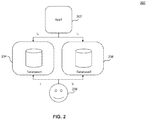
- FIG. 2 illustrates a system 200 for mitigating the contention problem described above with the system 100 illustrated in FIG. 1 .
- an application App 1 202 may have access to multiple separate single-threaded databases, e.g., at least Database 1 204 and Database 2 206 . These multiple separate single-threaded databases may have substantially similar entries, in some embodiments.
- a user 208 directly or by way of a separate application (not shown), may also have access to the same multiple single-threaded databases, or at least to a subset thereof.
- App 1 202 may access Database 1 204 to write data, and user 208 may simultaneously access Database 2 206 , avoiding any possible contention problems.
- user 208 need not be concerned about concurrency (in this case, accessing at time t 0 the data that App 1 202 is simultaneously writing to Database 1 204 )
- any synchronization mechanisms or lack thereof between the multiple separate databases may be considered entirely independent of the functionality described here for purposes of this example.
- App 1 202 may write to Database 2 206 , writing the same update as the write to Database 1 204 at t 0 , or writing different data instead, to Database 2 206 .
- Database 1 204 may mirror the data in Database 2 406 (and/or vice-versa) after it is newly written, to maintain some degree of concurrency.
- the system 200 may not be able to scale up to larger numbers of applications and/or users, greater than the number of databases, database servers, and/or database clusters, without having to manage contention for data and other resources.
- system 200 may use state indicators including signals, shared memory, semaphores, flags, files (such as in another filesystem or a table in another database) and/or other comparable constructs or techniques for interprocess communications and/or parallel computing.
- Other resource-use policies may be defined to prevent deadlocks or other execution hazards.
- State indicators such as those listed above may be periodically polled for enforcement of resource-use policies, such as by one or more watchdog processes and/or event handlers, such as in systems configured to respond to event-driven triggers, in some embodiments.
- system 200 is implemented with particular database architectures specifically designed to keep user- and/or read/write-state information of databases in a similar manner (e.g., DynamoDB, to name one non-limiting, non-exhaustive example), just the overhead of tracking, maintaining, and/or managing state may quickly become unsustainable for large numbers of applications concurrently writing to any given cluster(s) with a finite number of nodes.
- database architectures specifically designed to keep user- and/or read/write-state information of databases in a similar manner
- DynamoDB to name one non-limiting, non-exhaustive example
- scaling of this system 200 may be relatively more effective at handling contention for larger numbers of applications and/or users, but such scale-up would also require considerably more resources and expense to set up, scale up, and maintain. This may be the case even more so when maintaining a specific level of quality of service, especially when a system provider or administrator wishes to ensure that users are served with no unexpected delays, slowdowns, or other system failures.
- system 200 of FIG. 2 may incur degraded performance and quality of service as applications and/or users exceed certain numbers relative to a given number of databases.
- system 200 is somewhat scalable to accommodate increased demand from applications and/or users.
- Another ensuing problem may be that, because only one application or user may be able to access the single-threaded database at any given time, all writes must be sequential, such that a subsequent write cannot begin until the previous write has ended. Essentially, each accessing process locks or blocks the database for one write at a time. As will be appreciated by persons skilled in the relevant art(s), such locking, blocking, and/or contention may result in significant slowdowns.
- FIGS. 3-6 present embodiments that solve the problems discussed above with respect to FIGS. 1 and 2 .
- One way to solve these problems may involve decoupling application output from database persistence. Compared to an architecture in which output from each application must be written directly into any given database as soon as possible or risk hanging if a database is not available, this disclosure describes improved systems in which information (data, which may include metadata) may be stored intermediately, such as in a common filesystem, and then separately inserted into a single-threaded database cluster quickly and in an orderly fashion, without locking or otherwise interrupting access to the database by other applications.
- information data, which may include metadata
- FIG. 3 illustrates an alternative system 300 configured to decouple application output operations from database-cluster write operations, and includes mass-insertion functionality to streamline the eventual write operations to store application output information persistently in a database cluster.
- the decoupling may effectively be a result of one or more layers or stages of separation, comprising at least one storage module and/or at least one specialized operation module as intermediate modules between a database cluster and any or all applications accessing the database cluster.
- Storage layer 310 may be a unified data store, common filesystem, or shared storage in which application output data may be addressed and temporarily stored, in some embodiments, some examples of which may include any of a local volume or dataset (e.g., XFS, ZFS, etc.), network share (e.g., NFS, CIFS, etc.), network-attached storage (NAS) backed with any of the above storage types, storage area network (SAN) shared-disk filesystems, distributed filesystem (e.g., HDFS, GFS, etc.), or any combination thereof.
- a local volume or dataset e.g., XFS, ZFS, etc.
- network share e.g., NFS, CIFS, etc.
- NAS network-attached storage
- the storage layer 310 may provide a single abstraction, including a common (or merged or unified) address space or namespace, to accommodate an arbitrary amount of application output data 312 - 318 corresponding to each application 302 - 308 in any convenient order or in no particular order.
- storage layer 310 may be an object-storage layer, offline or online, including cloud-based object storage or hybrid storage (e.g., S3, Ceph, Minio, etc.).
- application output data 312 - 318 corresponding to each application 302 - 308 may be stored as objects in the storage layer 310 as separate objects.
- the separate objects may reside on the same common filesystem as described above, or they may be independently distributed, such as in a cloud or cloud-like environment.
- independently distributed objects may be addressed, referenced, and/or accessed using a single (unified or merged) abstraction as if they were on a single common filesystem.
- any of the above (or similar) embodiments of storage layer 310 applications, such as App 1 -AppN 302 - 308 no longer need to write directly to any single-threaded database cluster interface (unlike in FIG. 1 ). Rather applications may write, each at its own convenience, to the storage layer 310 instead.
- This feature eliminates the need for managing contention between applications and/or users and renders application output, and possibly some general operations per application, independent of other applications and their operations and/or outputs. When an application finishes writing its output data into data storage, the application may terminate.
- object storage may be especially advantageous for storing a relatively large number of relatively small chunks of data generated from any number of applications, particularly in scenarios where concurrency and update latency with respect to a given object are of less concern, but where availability and read latency are more highly valued.
- One example of such a particular scenario may be with generating, collecting, updating, and/or accessing content recommendations for streaming media services, along with content metadata and user profile information used for creating those content recommendations.
- sources of these content recommendations may generate billions of records in relatively short time intervals, which may need to be persistently stored in a database within a relatively short time.
- data concurrency may not be a high priority at any given time, these outputs from content recommendation sources may later be inputs for future content recommendations.
- each application need not be aware of the existence of any other application.
- Listener 320 may periodically “listen” for new data or files, actively polling for new changes based on triggering events, schedules, or similar constructs, which constitute an update policy. In some embodiments, such listening may be carried out by periodically fetching or listing the contents of a filesystem, monitoring snapshot (copy-on-write, journal, delta, etc.) listings or status information, or querying an object-storage API, or executing system calls, to name a few non-limiting, non-exhaustive examples in some embodiments.
- the listener 320 may passively wait for specific signals, system calls, (file)system notifications, etc., or any combination thereof.
- passive or periodic actions may be performed by lambda functions (lambda calculus), functional programming (function-level programming), meta-programming, multi-stage programming, multi-paradigm programming, etc. Such programming may have the added effect of saving additional resources overall and being able to be offloaded to cloud-based or other off-site and/or third-party services.
- the latter techniques of the certain other embodiments may not be available on all systems or databases, but may, where available, increase or decrease overall efficiency of the storage layer 310 , listener 320 , and/or mass-insertion module 322 , depending on average fill rate of the storage layer 310 (or particular outputs or Objects therein), processing overhead of the listener 320 , and/or processing overhead of mass-insertion operations performed by the mass-insertion module 322 . While fill rates and average fill rate pertaining to the storage layer 310 may depend on external factors of the applications and any of their users, data sources, and any expected output, processing overhead of listener 320 and mass-insertion module 322 may also depend on implementation details intrinsic to each.
- listener 320 may be made aware of execution states of applications corresponding to specific output data and/or objects written (or being written) in the storage layer 310 . This may be done using any of the state indicators and/or other interprocess communications or similar techniques disclosed herein. As noted above, when an application finishes writing its output data into data storage, the application may terminate in embodiments where this behavior may the expected behavior in a given alternative system 300 , then listener 320 may also observe and/or await a change in execution state of an application writing a corresponding output (e.g. App 2 304 writing to Out 2 314 ). Efficient operation in these embodiments would dictate that listener 320 wait until termination of the writing application before further processing any of the corresponding data written into the storage layer 310 .
- App 2 304 writing to Out 2 314
- listener 320 may, according to programmable rule(s), schedule(s), and/or predetermined algorithm(s), relay relevant new information and/or metadata thereof to another module, such as mass-insertion module 322 to feed the new data (possibly from many applications) into database cluster 332 in a manner that may be more efficient for the database cluster 332 and/or one or more database nodes 324 - 330 therein, in some embodiments.
- another module such as mass-insertion module 322 to feed the new data (possibly from many applications) into database cluster 332 in a manner that may be more efficient for the database cluster 332 and/or one or more database nodes 324 - 330 therein, in some embodiments.
- mass-insertion module 322 may be an existing feature in a database implementation (e.g., Redis, DB2, etc.). Where an existing mass-insertion module 322 is not already implemented by default, a comparably functional module may be custom-implemented.
- the custom implementation may be platform-native, a plugin, wrapper, shell script, etc., or any combination thereof, to name a few non-limiting, non-exhaustive example embodiments.
- mass-insertion module 322 may accept its input (in this embodiment, input to mass-insertion module 322 may be output of at least one application 302 - 308 ) in a standard format (e.g., JSON, XML, key-value pair plain text, etc.), or alternatively may require or favor its input in a preferred custom protocol (compacted, custom binary, compressed with quick algorithm(s), etc.) to improve processing speed and/or reduce processing overhead, for example. To this end, it may be necessary to have applications 302 - 308 output their output data in the preferred or required format(s) or use a separate module (not shown) to perform conversion of expected application output data to a preferred or required format dictated by the mass-insertion module 322 .
- a standard format e.g., JSON, XML, key-value pair plain text, etc.
- a preferred custom protocol compacted, custom binary, compressed with quick algorithm(s), etc.
- any of Node 1 -NodeK 112 - 118 may mirror the data in any or all of the other nodes (and/or vice-versa) after it is newly written.
- there still may be other bottlenecks encountered when trying to synchronize and maintain some degree of concurrency and consistency with a cluster of single-threaded databases such as database cluster 332 even with the improvements of the alternative system 300 depicted in FIG. 3 . This may be especially the case as the limitations of single-threaded databases may limit the ability to leverage the distributed nature of databases in database clusters such as database cluster 332 . Techniques discussed below with respect to FIG. 5 may considerably enhance performance of single-threaded database clusters.
- data written from the mass-insertion module 322 may be serialized to allow for a large write (batch write, serial write, or mass insertion) operation to insert new entries all at once, rather than waiting for bidirectional communications with the database, in some embodiments.
- This advantage has been shown to yield a noticeable improvement over certain approaches.
- tests have shown empirically that the mass-insertion module 322 of FIG. 3 tends to improve performance over Redis embodiments of FIG. 2 by 5 ⁇ - to 10 ⁇ -reductions in access latency.
- Other embodiments may vary depending on database implementation, data types, data sizes (e.g., of content recommendations), etc.
- FIG. 3 performance may be enhanced further still, by combining the improvements of FIG. 3 with the improvements of FIG. 2 . This may be seen in FIG. 4 and described below in the accompanying description of FIG. 4 .
- FIG. 4 illustrates a combined system 400 , adapting a parallel multi-database architecture similar to that of system 200 of FIG. 2 to use a storage layer, a listener-type element, and an intermediate module such as the mass-insertion module in the architecture of the alternative system 300 of FIG. 3 .
- These added features of the alternative system 300 may streamline write accesses enough for smoothly accommodating more applications (App 1 -AppN 402 - 408 ) compared to the system 200 of FIG. 2 .
- an application may output data to be ultimately stored in at least one of multiple separate single-threaded databases, e.g., at least Database 1 424 and Database 2 426 .
- These multiple separate single-threaded databases, including Database 1 424 and Database 2 426 may have substantially similar entries.
- These databases represent one example; other embodiments may use a database cluster in lieu of any database, conceptually similar to database cluster 332 of FIG. 3 above.
- this exemplary embodiment of FIG. 4 shows two databases, but in practice, any number of databases or database clusters may be deployed and used in the same manner as shown here.
- a user 428 directly or by way of a separate application (not shown), also has access to the same multiple single-threaded databases, or at least to a subset thereof.
- Storage layer 410 may be a unified data. store, common filesystem, or shared storage in which application output data may be addressed and temporarily stored, in some embodiments, some examples of which may include any of a local volume or dataset, network share, NAS backed with any of the above storage types, SAN shared-disk filesystems, distributed filesystem, or any combination thereof.
- the storage layer 410 may provide a single abstraction, including a common (or merged or unified) address space or namespace, to accommodate an arbitrary amount of application output data 412 - 418 corresponding to each application 402 - 408 in any convenient order or in no particular order.
- storage layer 410 may be an object-storage layer, offline or online, including cloud-based object storage or hybrid storage.
- application output data 412 - 418 corresponding to each application 402 - 408 may be stored as objects in the storage layer 410 as separate objects.
- the separate objects may reside on the same common filesystem as described above, or they may be independently distributed, such as in a cloud or cloud-like environment.
- independently distributed objects may be addressed, referenced, and/or accessed using a single (unified or merged) abstraction as if they were on a single common filesystem.
- Listener 420 may periodically “listen” for new data or files, actively polling for new changes based on triggering events, schedules, or similar constructs, which constitute an update policy. In some embodiments, such listening may be carried out by periodically fetching or listing the contents of a filesystem, monitoring snapshot (copy-on-write, journal, delta, etc.) listings or status information, or querying an object-storage API, or executing system calls, to name a few non-limiting, non-exhaustive examples in some embodiments.
- the listener 420 may passively wait for specific signals, system calls, (file)system notifications, etc., or any combination thereof.
- passive or periodic actions may be performed by lambda functions (lambda calculus), functional programming (function-level programming), meta-programming, multi-stage programming, multi-paradigm programming, etc. Such programming may have the added effect of saving additional resources overall and being able to be offloaded to cloud-based or other off-site and/or third-party services.
- the latter techniques of the certain other embodiments may not be available on all systems or databases, but may, where available, increase or decrease overall efficiency of the storage layer 410 , listener 420 , and/or mass-insertion module 422 , depending on average fill rate of the storage layer 410 (or particular outputs or objects therein), processing overhead of the listener 420 , and/or processing overhead of mass-insertion operations performed by the mass-insertion module 422 . While fill rates and average fill rate pertaining to the storage layer 410 may depend on external factors of the applications and any of their users, data sources, and any expected output, processing overhead of listener 420 and mass-insertion module 422 may also depend on implementation details intrinsic to each.
- applications such as App 1 -AppN 402 - 408 may no longer need to write directly into any single-threaded database (unlike in FIG. 2 ). Rather, applications may write, each at its own convenience, to the storage layer 410 instead.
- This feature eliminates the need for managing contention between applications and/or users and renders application output, and possibly some general operations per application, independent of other applications and their operations and/or outputs. When an application finishes writing its output data into data storage, the application may terminate.
- object storage may be especially advantageous for storing a relatively large number of relatively small chunks of data generated from any number of applications, particularly in scenarios where concurrency and update latency with respect to a given object are of little concern, but where availability and read latency are more highly valued.
- One example of such a particular scenario would be with generating, collecting, updating, and/or accessing content recommendations for streaming media services, along with content metadata and user profile information used for creating those content recommendations.
- this disclosure is not limited to that example scenario.
- user 428 may access Database 2 426 at the same time Database 1 is being written to by another process (e.g., from mass-insertion module 422 instead of any of App 1 -AppN 402 - 408 ), avoiding any possible contention problems.
- another process e.g., from mass-insertion module 422 instead of any of App 1 -AppN 402 - 408
- any synchronization mechanisms or lack thereof between the multiple separate databases is not relevant for purposes of this example.
- mass-insertion module 422 may write to Database 2 426 , writing the same update as the write to Database 1 424 at t 0 , or writing different data instead, to Database 2 426 .
- user 428 may separately access Database 1 424 .
- Database 1 424 may mirror the data in Database 2 426 (and/or vice-versa) after it is newly written, to have some degree of concurrency.
- the system 400 may not be able to scale up to larger numbers of applications and/or users, greater than the number of databases, database servers, and/or database clusters, without having to manage contention for data and other resources.
- system 400 may also use state indicators including signals, shared memory, semaphores, flags, files (such as in another filesystem or a table in another database) and/or other comparable constructs or techniques for interprocess communications and/or parallel computing.
- resource-use policies may be defined to prevent deadlocks or other execution hazards.
- State indicators such as those listed above may be periodically polled for enforcement of resource-use policies, such as by one or more event handlers and/or watchdog processes.
- passive or periodic actions may be performed by lambda functions, functional programming, meta-programming, multi-stage programming, multi-paradigm programming, etc. Such programming may have the added effect of saving additional resources overall and being able to be offloaded to cloud-based or other off-site and/or third-party services, which may beneficially yield a net savings in operating costs.
- system 400 is implemented with particular database architectures specifically designed to keep state in a similar manner, just the overhead of maintaining and/or managing state may quickly become unsustainable for large numbers of applications concurrently writing to any given cluster(s) with a finite number of nodes.
- much of the benefit that may be realized from system 400 may be attributed more to features of elements 410 - 422 of FIG. 4 (corresponding to elements 310 - 322 of FIG. 3 ) rather than the parallel database architecture of multiple single-threaded databases.
- Such benefits of the features of elements 410 - 422 of FIG. 4 may be further leveraged by tuning structure(s) and algorithm(s) used to manage database clusters, as opposed to implementing multiple-database architectures such as those shown in FIG. 2
- scaling this system 400 in order to handle contention for larger numbers of applications and/or users may be relatively more efficient, but such scale-up may also require considerably more resources and expense to set up, scale up, and maintain, although not necessarily as much as would be required for system 200 . This may be the case even more so when maintaining a specific level of quality of service, especially when a system provider or administrator wishes to ensure that users are served with no unexpected delays, slowdowns, and/or other system failures.
- this system 400 may mitigate access latency as well as contention for data and resources.
- writes such as from the mass-insertion module 422 , may still be made more efficient, such as by leveraging distributed database clusters rather than sequentially or serially accessing multiple separate single-threaded databases. More details on such improvements are discussed with respect to FIG. 5 below.
- FIG. 5 illustrates a block diagram of a new clustered system 500 according to an example embodiment.
- elements pertaining to single-threaded databases are at a disadvantage in database cluster settings, where a single interface may block a whole cluster waiting for any single node to complete a write, for example.
- This shortcoming limits database cluster performance, in one or more aspects at least by hindering distributed access and parallelism.
- Partial solutions shown in FIG. 2 and improved in FIG. 4 may reduce contention for resources and data, but these partial solutions may be incomplete in that they may still be subject to some degree of contention among competing applications and/or users attempting to access any one of the databases. Additionally, these partial solutions may not scale up efficiently, if they could be scaled up at all.
- the improved partial solutions of FIGS. 3 and 4 may realize the full benefit of this Detailed Disclosure, but only if they access one single-threaded database at a time or operate on a database “cluster” having only one node.
- FIGS. 3 and 4 may implement an intermediate module in the form of a mass-insertion module 322 and 422 , respectively, as a single application making the only writes to a database cluster 332 or individual database(s) 424 and 426 , for example. While this may reduce contention and latency, limitations of single-threaded databases may still remain. Such limitations may be mitigated where multiple databases are available, with added advantages when the multiple single-threaded databases are in a distributed database cluster. Single-threaded databases may be used where multi-threaded operation is deactivated, impossible, or otherwise unavailable.
- clustered system 500 may include applications App 1 -AppN 502 - 508 , storage layer 510 , output data 512 - 518 , and listener 520 , and each may work in the same manner as corresponding elements 302 - 320 from FIG. 3 and/or 402-420 from FIG. 4 .
- Database cluster 534 with nodes Node 1 -NodeK 536 - 542 may be provided in a configuration similar to that of database cluster 332 and its respective nodes Node 1 -NodeK 324 - 330 as shown in FIG. 3 .
- each node of Node 1 -NodeK 536 - 542 may be a separate database.
- Listener 520 may periodically “listen” for new data or files, actively polling for new changes based on triggering events, schedules, or similar constructs, which constitute an update policy. In some embodiments, such listening may be carried out by periodically fetching or listing the contents of a filesystem, monitoring snapshot (copy-on-write, journal, delta, etc.) listings or status information, or querying an object-storage API, or executing system calls, to name a few non-limiting, non-exhaustive examples in some embodiments.
- the listener 520 may passively wait for specific signals, system calls, (file) system notifications, etc., or any combination thereof.
- passive or periodic actions may be performed by lambda functions (lambda calculus), functional programming (function-level programming), meta-programming, multi-stage programming, multi-paradigm programming, etc. Such programming may have the added effect of saving additional resources overall and being able to be offloaded to cloud-based or other off-site and/or third-party services.
- the latter techniques of the certain other embodiments may not be available on all systems or databases, but may, where available, increase or decrease overall efficiency of the storage layer 510 , listener 520 , and/or mass-insertion module 522 , depending on average fill rate of the storage layer 510 (or particular outputs or objects therein), processing overhead of the listener 520 , and/or processing overhead of mass-insertion operations performed by the intermediate module such as computer cluster 522 . While fill rates and average fill rate pertaining to the storage layer 510 may depend on external factors of the applications and any of their users, data sources, and any expected output, processing overhead of listener 520 and computer cluster 522 may also depend on implementation details intrinsic to each.
- FIG. 5 shows one database cluster, but in practice, any number of databases or database clusters may be deployed and used in the same manner as shown here.
- a user may access one of the clusters while another cluster may be simultaneously updated via the computer cluster 522 .
- multiple database clusters may be operated in a manner similar to that of the multiple databases of system 200 in FIG. 2 and system 400 in FIG. 4 .
- each database (cluster) and/or node may be configured to store its data entries as key-value pairs.
- Node 1 -NodeK 536 - 542 in database cluster 534 may be further configured in a distributed and/or partitioned schema, such that each node is configured to store only values corresponding to keys having a certain hash, in order to provide easy search and access of database entries, in each node and across a given database cluster. This arrangement may be referred to as slot partitioning or hash-bucket indexing, in some further embodiments.
- Each node would have a substantially equal number of hashes, in some embodiments.
- each node would have approximately Z ⁇ K ⁇ 1 slots (K ⁇ 1 or 1/K of the total possible slots, for Z/K actual slots) assigned to it, in some embodiments, allowing for rounding, platform-specific tolerances, etc.
- computer cluster 522 may be used for the same purpose of mass insertion of data entries into the database cluster 534 .
- a cluster such as computer cluster 522 may be configured to ensure quick and reliable distributed mass-insertion operations in single-threaded database clusters such as database cluster 534 .
- computer cluster 522 may be organized and operated according to a framework and/or platform suitable for clustered computing and/or storage, including Hadoop, Spark, Storm, Flume, Oozie, YARN, HPCC, Impala, etc., to name a few non-limiting examples.
- the computer cluster 522 may have at least one node that serves as a driver 524 (also referred to as a master, in some embodiments), which in turn may interface with at least one other node in the computer cluster 522 .
- a driver 524 also referred to as a master, in some embodiments
- Such a node may serve as an executor, such as, e.g., Executor 1 -ExecutorM 526 - 532 (also referred to as slaves, in some embodiments).
- a benefit of using executors in a computer cluster 522 associated with database nodes in a database cluster 534 is that the executors, in these embodiments, may bypass the single-threaded database cluster interface, which would block all nodes if any node is being written. If each executor may have a direct line to each or any database node in the database cluster 534 , then the plurality of nodes in the database cluster may effectively be accessed and written in parallel with each other, in accordance with smart logic driving the executors to access the database cluster 534 efficiently without actually multi-threading the database cluster (without multi-threaded operation of the database nodes in the database cluster)7.
- computer cluster 522 may receive new data entries, such as via listener 520 .
- Driver 524 then may, according to an algorithm or rule(s), distribute at least one entry of data (or an object, in some embodiments that may use object storage at the storage layer 510 ), such as any of output data Out 1 -OutN 512 - 518 output by applications App 1 -AppN 502 - 508 stored in storage layer 510 .
- the data stored in storage layer 510 may include data entries, which may further include or which may themselves be key-value pairs.
- a computer may calculate a hash of the key and send the key-value pair to an executor of Executor 1 -ExecutorM 526 - 532 associated with a corresponding node of Node 1 -NodeK 536 - 542 according to the value of the hash calculated for the key, where the hash calculated for the key falls within a range of hashes assigned to the corresponding node, in some embodiments.
- each key may reside on only one database node (not counting backup or spare nodes).
- Each node in the database cluster may be accessed by an executor, e.g., one of Executor 1 -ExecutorM 526 - 532 , configured to perform a mass-insertion operation on the corresponding node associated with the corresponding executor.
- each executor may perform mass-insertion operations on at least one database node in the database cluster 534 , but each node may receive data from only one associated executor. This may prevent contention problems while maintaining efficiency of provisioning the computer cluster 522 , in some embodiments.
- the database nodes of the database cluster 534 are of quantity K
- the executor nodes (executors/slaves) of the computer cluster 522 are of quantity M, where M may be less than or equal to K according to a desired tradeoff of provisioning to performance (M ⁇ K).
- M may be less than or equal to K according to a desired tradeoff of provisioning to performance (M ⁇ K).
- M may be less than or equal to K according to a desired tradeoff of provisioning to performance (M ⁇ K).
- M may be less than or equal to K according to a desired tradeoff of provisioning to performance (M ⁇ K).
- M provisioning to performance
- M were greater than K, then there would be at least one executor node in the computer cluster 522 that may always be idle with respect to database cluster 534 .
- Such overprovisioned or redundant nodes may be mirrored, replicated, or otherwise quickly recoverable hot spares to be used as fail-safe measures to ensure reliable operation and availability of cluster resources.
- numbers of overprovisioned or redundant (spare) nodes are not factored into the counts of quantity K and quantity M, for illustrative purposes of FIG. 5 .
- a clustered system 500 may realize benefits of easier scalability, quantity K of database nodes may grow faster than quantity M of executors (M ⁇ K), although quantity M may also be scaled up eventually to meet demand from growing quantity K, in some embodiments. Additionally, computer clusters such as computer cluster 522 may enhance systems with the flexibility of their inherent distributed nature, for example, as any executor may be repurposed from performing mass-insertion operations in one database node to performing mass-insertion operations in at least one other database node.
- the new clustered system 500 may realize further advantages of fault-tolerance and resiliency: if an executor node fails during a mass-insertion write operation, a spare or different executor node may be brought online in order to continue the process smoothly.
- a streaming media content player device may comprise, execute, and run at least one application at a given time for a given user.
- the streaming media subscription service may have a vast network comprising hundreds of millions of users, each using at least one content player device, each running at least one application.
- Each application may generate at least one content recommendation for a specific user, at varying time intervals, sometimes every second or more frequently, such as when a user is browsing a large list of content options or when a user is consuming certain parts of certain other content titles. It should be understood that this disclosure is not limited to this example use case.
- Content recommendations may be relatively small data entries, in some embodiments.
- a user-specific content recommendation may be a key-value pair made up of a key, such as a unique user ID, and a value, being at least a unique identifier of a content title.
- the content recommendation may be a data structure containing more metadata relating to the recommended content title. Otherwise, the unique identifier of a content title may be used by itself to reference more information about the recommended content title.
- These recommendations may need to be stored, at least so that they may be analyzed for trends over time and across varying groups of users, and so that they may be fed back into future content recommendations, in some embodiments. As such, real-time concurrency of data may not be as important as simply ensuring that the content recommendation data are eventually written into storage in relatively short order, without overwhelming system resource capacity.
- FIG. 6 illustrates a flowchart representing a mass-insertion operation for single-threaded database clusters, according to some embodiments.
- Process 600 may be performed by processing logic that may include hardware (e.g., circuitry, dedicated logic, programmable logic, microcode, etc.), software (e.g., instructions executing on a processing device), or any combination thereof.
- processing logic may include hardware (e.g., circuitry, dedicated logic, programmable logic, microcode, etc.), software (e.g., instructions executing on a processing device), or any combination thereof.
- a processor such as processor 704 may be configured to interface with a plurality of software applications, such as App 1 -AppN 502 - 508 .
- a system may standardize on an application programming interface (API), based on which, various software applications, potentially including third-party software applications, may communicate with the system powered by the processor 704 .
- API application programming interface
- the system may be entirely automated, not requiring any regular intervention from users or administrators.
- processor 704 may receive data output from the software applications, such as Out 1 -OutN 512 - 518 , each respectively corresponding to App 1 -AppN 502 - 508 .
- the software applications such as Out 1 -OutN 512 - 518 , each respectively corresponding to App 1 -AppN 502 - 508 .
- resources required may vary.
- the plurality of software applications may collectively generate many billions of data entries at a time, such as for streaming media content recommendations.
- processor 704 may detect a presence, via a listener, such as listener 520 , of information newly stored within storage layer. This detection may not necessarily always be happening in a system that embodies these elements disclosed herein. However, when certain patterns are detected, then additional steps may be taken, such as for information security, efficiency of access, constraints on time and/or memory space. If no new information is detected in a given monitoring area, then execution may default to actions related to 608 below, of maintaining a database cluster, for example. Other incidental functions may be defined. If new information is detected by our system, then execution may proceed to 610 , as explained below.
- processor 704 may be further used to maintain at least one database cluster, wherein nodes have multi-threaded execution properties, in some embodiments. In some embodiments, it may be just a small number, as low as two, of single-threaded database nodes running in a cluster, such that benefits of this description may be realized. From here, execution may return to at least either of 604 or 606 , depending on available data to monitor.
- processor 704 may then execute an intermediate module, such as computer cluster 522 .
- an intermediate module 522 such as a mass-insertion module 422 , to perform mass-insertion operations in a database cluster of single-threaded databases. Execution of this intermediate module may be triggered by relaying or sending at least some of this information to it, in some embodiments. Execution may then pass to 612 .
- the intermediate module may send at least some of the new information to a database cluster, such as database cluster 534 .
- a database cluster such as database cluster 534 .
- various techniques may be used, of varying complexity. The least complex embodiments may attempt simple writes to the cluster, in some embodiments, but these such writes often fail without other ways of managing contention, sequential input/output (I/O) delays, etc. Thus, execution may then pass to 614 .
- processor 704 may then perform, via the intermediate module, simultaneous access to nodes within the database cluster. This action may also be referred to as a mass insertion. Depending on the structure of each of the database cluster and the intermediate module, e.g., as computer cluster 522 , such simultaneous access may be improved by using a plurality of executor nodes Executor 1 -ExecutorM 526 - 532 , as described with respect to FIG. 5 above.
- Process 600 is disclosed in the order shown above in this exemplary embodiment of FIG. 6 .
- the operations disclosed above, alongside other operations, may be executed sequentially in any order, or they may alternatively be executed concurrently, with more than one operation being performed simultaneously, or any combination of the above.
- Computer system 700 may be any computer or computing device capable of performing the functions described herein.
- one or more computer systems 700 may be used to implement any embodiments of FIGS. 1-6 , and/or any combination or sub-combination thereof.
- system frameworks described herein may be implemented as a method, process, apparatus, or article of manufacture such as a non-transitory computer-readable medium or device.
- present system frameworks may be described in the context of database dusters. It should be appreciated, however, that the present framework may also be applied in processing other types of cluster computing that may perform batch operations on single-threaded nodes of other clusters.
- Any applicable data structures, file formats, and schemas may be derived from standards including but not limited to JavaScript Object Notation (JSON), Extensible Markup Language (XML), Yet Another Markup Language (YAML), Extensible Hypertext Markup Language (XHTML), Wireless Markup Language (WML), MessagePack, XML User Interface Language (XUL), or any other functionally similar representations alone or in combination.
- JSON JavaScript Object Notation
- XML Extensible Markup Language
- YAML Yet Another Markup Language
- XHTML Extensible Hypertext Markup Language
- WML Wireless Markup Language
- MessagePack XML User Interface Language
- XUL XML User Interface Language
- the data, files, and/or databases may be stored, retrieved, accessed, and/or transmitted in human-readable formats such as numeric, textual, graphic, or multimedia formats, further including various types of markup language, among other possible formats.
- the data, files, and/or databases may be stored, retrieved, accessed, and/or transmitted in binary, encoded, compressed, and/or encrypted formats, or any other machine-readable formats.
- Interfacing or interconnection among various systems and layers may employ any number of mechanisms, such as any number of protocols, programmatic frameworks, floorplans, or application programming interfaces (API), including but not limited to Document Object Model (DOM), Discovery Service (DS), NSUserDefaults, Web Services Description Language (WSDL), Message Exchange Pattern (MEP), Web Distributed Data Exchange (WDDX), Web Hypertext Application Technology Working Group (WHATWG) HTML7 Web Messaging, Representational State Transfer (REST or RESTful web services), Extensible User Interface Protocol (XUP), Simple Object Access Protocol (SOAP), XML Schema Definition (XSD), XML Remote Procedure Call (XML-RPC), or any other mechanisms, open or proprietary, that may achieve similar functionality and results.
- API application programming interfaces
- Such interfacing or interconnection may also make use of uniform resource identifiers (URI), which may further include uniform resource locators (URL) or uniform resource names (URN).
- URI uniform resource identifiers
- URL uniform resource locators
- UPN uniform resource names
- Other forms of uniform and/or unique identifiers, locators, or names may be used, either exclusively or in combination with forms such as those set forth above.
- Any of the above protocols or APIs may interface with or be implemented in any scripting or programming language, procedural, functional, or object-oriented, and may be assembled, compiled, or interpreted.
- Non-limiting examples include C, C++, C#, Objective-C, Java, Swift, Go, Ruby, Rust, Perl, Python, JavaScript, WebAssembly, or virtually any other language, with any other libraries or schemas, in any kind of framework, runtime environment, virtual machine, interpreter, shell, stack, engine, or similar mechanism, including but not limited to Node.js, jQuery, Dojo, Dijit, OpenUI7, AngularJS, Express.js, Backbone.js, Ember.js, DHTMLX, React, Chakra, SpiderMonkey, V8, Electron, XULRunner, WebRunner, WebEngine, Prism, AIR, Blink, CEF Cordova, among many other non-limiting examples.
- Embodiments disclosed herein may be implemented and/or performed with any database framework, regardless of capabilities for single- or multi-threaded operation, including well-known examples of database implementations such as Redis, SSDB, LevelDB, Bigtable, Bluefish, Cassandra, Hypertable, HyperDex, Coord, Druid, Accumulo, HBase, Ignite, Tarantool, Actord, Memcached, MemcacheQ, Repcached, JBoss Cache, Infinispan, Coherence, Hazelcast, Voldemort, Scalaris, Riak, KAI, KDI, Aerospike, ArangoDB, Berkeley DB, Cosmos DB, CouchDB, DocumentDB, DovetailDB, DynamoDB, FoundationDB, InfinityDB, LMDB, MemcacheDB, MongoDB, NMDB, ObjectivityDB, OrientDB, QuasarDB, RethinkDB, RocksDB, SimpleDB, ZopeDB, Mnesia, River, Virtuo
- NewSQL architectures including MemSQL, NuoDB, VoltDB, Spanner, Gridgain, Trafodion, Clustrix, or other related solutions including MySQL Cluster, InnoDB, InfiniDB, TokuDB, MyRocks, Infobright, Vitess, Scalebase, and others.
- Other traditional SQL-based implementations such as Postgres (PostgreSQL), MariaDB, MySQL, DB2, MS-SQL, SQL Server, SQLite, and other relational databases may be adapted to benefit from techniques described herein.
- Other benefits realized from the techniques described herein apply particularly well to big data on cluster-based platforms including Hadoop, HFS, GFS, HPCC, Sector, Sphere, Mahout, etc.
- Computer system 700 includes one or more processors (also called central processing units, or CPUs), such as a processor 704 .
- processors also called central processing units, or CPUs
- Processor 704 is connected to a bus or communication infrastructure 706 .
- Computer system 700 also includes user input/output device(s) 703 , such as monitors, keyboards, pointing devices, etc., which communicate with communication infrastructure 706 through user input/output interface(s) 702 .
- user input/output device(s) 703 such as monitors, keyboards, pointing devices, etc., which communicate with communication infrastructure 706 through user input/output interface(s) 702 .
- One or more processors 704 may each be a graphics processing unit (GPU).
- a GPU is a processor that is a specialized electronic circuit designed to process mathematically intensive applications.
- the GPU may have a parallel structure that is efficient for parallel processing of large blocks of data, such as mathematically intensive data common to computer graphics applications, images, videos, etc.
- Computer system 700 also includes a primary memory or main memory 708 , such as random access memory (RAM).
- Main memory 708 may include one or more levels of cache.
- Main memory 708 has stored therein control logic (i.e., computer software) and/or data.
- Computer system 700 may also include one or more secondary storage devices or secondary memory 710 .
- Secondary memory 710 may include, for example, a hard disk drive 712 and/or a removable storage device or drive 714 .
- Removable storage drive 714 may be a floppy disk drive, a magnetic tape drive, a compact disk drive, an optical storage device, tape backup device, and/or any other storage device/drive.
- Removable storage drive 714 may interact with a removable storage unit 718 .
- Removable storage unit 718 includes a computer usable or readable storage device having stored thereon computer software (control logic) and/or data.
- Removable storage unit 718 may be a floppy disk, magnetic tape, compact disk, MD, optical storage disk, and/any other computer data storage device.
- Removable storage drive 714 reads from and/or writes to removable storage unit 718 in a well-known manner.
- secondary memory 710 may include other means, instrumentalities or other approaches for allowing computer programs and/or other instructions and/or data to be accessed by computer system 700 .
- Such means, instrumentalities or other approaches may include, for example, a removable storage unit 722 and an interface 720 .
- the removable storage unit 722 and the interface 720 may include a program cartridge and cartridge interface (such as that found in video game devices), a removable memory chip (such as an EPROM or PROM) and associated socket, a memory stick and USB port, a memory card and associated memory card slot, and/or any other removable storage unit and associated interface.
- Computer system 700 may further include a network interface or communication interface 724 .
- Communication interface 724 enables computer system 700 to communicate and interact with any combination of remote devices, remote networks, remote entities, etc. (individually and collectively referenced by reference number 728 ).
- communication interface 724 may allow computer system 700 to communicate with remote devices 728 over communications path 726 , which may be wired and/or wireless, and which may include any combination of LANs, WANs, the Internet, etc. Control logic and/or data may be transmitted to and from computer system 700 via communications path 726 .
- a computer system may also be any one of a personal digital assistant (PDA), desktop workstation, laptop or notebook computer, netbook, tablet, smart phone, smart watch, or embedded system, to name a few non-limiting examples.
- PDA personal digital assistant
- desktop workstation laptop or notebook computer
- netbook tablet
- smart phone smart watch
- embedded system to name a few non-limiting examples.
- Any such computer system 700 may run any type of application associated with a layered repository facility, including legacy applications, new applications, etc.
- Computer system 700 may be a client or server, accessing or hosting any applications through any delivery paradigm, including but not limited to remote or distributed cloud computing solutions; local or on-premises software (“on-premise” cloud-based solutions); “as a service” models, e.g., content as a service (CaaS), digital content as a service (DCaaS), software as a service (SaaS), managed software as a service (MSaaS), platform as a service (PaaS), desktop as a service (DaaS), framework as a service (FaaS), backend as a service (BaaS), mobile backend as a service (MBaaS), or infrastructure as a service (IaaS); or a hybrid model including any combination of the foregoing examples or other comparable services or delivery paradigms.
- “as a service” models e.g., content as a service (CaaS), digital content as a service (DCaaS), software as a service (SaaS
- a non-transitory, tangible apparatus or article of manufacture comprising a tangible, non-transitory computer-useable or computer-readable device or medium having control logic (software) stored thereon is also referred to herein as a computer program product or program storage device.
- control logic when executed by one or more data processing devices (such as computer system 700 ), causes such data processing devices to operate as described herein.
- the computer system 700 may include, but is not limited to, a mobile phone or other mobile device, a personal digital assistant (PDA), a computer, a cluster of computers, a set-top box, a smart watch, a smart phone, a tablet, VR/AR headset or helmet, or other types of device capable of processing instructions and receiving and transmitting data to and from humans and other computing devices.
- PDA personal digital assistant
- references herein to “one embodiment,” “an embodiment,” “an example embodiment,” or similar phrases indicate that the embodiment described may include a particular feature, structure, or characteristic, but every embodiment may not necessarily include the particular feature, structure, or characteristic. Moreover, such phrases are not necessarily referring to the same embodiment. Further, when a particular feature, structure, or characteristic is described in connection with an embodiment, it would be within the knowledge of persons skilled in the relevant art(s) to incorporate such feature, structure, or characteristic into other embodiments whether or not explicitly mentioned or described herein. Additionally, some embodiments may be described using the expression “coupled” and “connected” along with their derivatives. These terms are not necessarily intended as synonyms for each other.
- Coupled may also mean that two or more elements are not in direct contact with each other, but yet still co-operate or interact with each other.
- references herein to “one embodiment,” “an embodiment,” “an example embodiment,” or similar phrases indicate that the embodiment described may include a particular feature, structure, or characteristic, but every embodiment may not necessarily include the particular feature, structure, or characteristic. Moreover, such phrases may not necessarily be referring to the same embodiment. Further, when a particular feature, structure, or characteristic is described in connection with an embodiment, it would be within the knowledge of persons skilled in the relevant art(s) to incorporate such feature, structure, or characteristic into other embodiments whether or not explicitly mentioned or described herein. Additionally, some embodiments may be described using the expression “coupled” and “connected” along with their derivatives. These terms are not necessarily intended as synonyms for each other.
- Coupled may also mean that two or more elements are not in direct contact with each other, but yet still co-operate or interact with each other.
Abstract
Description
Claims (24)
Priority Applications (5)
| Application Number | Priority Date | Filing Date | Title |
|---|---|---|---|
| US15/849,103 US10726051B2 (en) | 2017-12-20 | 2017-12-20 | Mass insertion into single-threaded databases |
| PCT/US2018/062562 WO2019125703A1 (en) | 2017-12-20 | 2018-11-27 | Mass insertion into single-threaded databases |
| EP18891115.0A EP3729291A4 (en) | 2017-12-20 | 2018-11-27 | Mass insertion into single-threaded databases |
| US16/939,758 US11663242B2 (en) | 2017-12-20 | 2020-07-27 | Mass insertion into single-threaded databases |
| US18/303,615 US20230259532A1 (en) | 2017-12-20 | 2023-04-20 | Mass insertion into single-threaded databases |
Applications Claiming Priority (1)
| Application Number | Priority Date | Filing Date | Title |
|---|---|---|---|
| US15/849,103 US10726051B2 (en) | 2017-12-20 | 2017-12-20 | Mass insertion into single-threaded databases |
Related Child Applications (1)
| Application Number | Title | Priority Date | Filing Date |
|---|---|---|---|
| US16/939,758 Continuation US11663242B2 (en) | 2017-12-20 | 2020-07-27 | Mass insertion into single-threaded databases |
Publications (2)
| Publication Number | Publication Date |
|---|---|
| US20190188314A1 US20190188314A1 (en) | 2019-06-20 |
| US10726051B2 true US10726051B2 (en) | 2020-07-28 |
Family
ID=66813956
Family Applications (3)
| Application Number | Title | Priority Date | Filing Date |
|---|---|---|---|
| US15/849,103 Active 2038-07-27 US10726051B2 (en) | 2017-12-20 | 2017-12-20 | Mass insertion into single-threaded databases |
| US16/939,758 Active 2038-03-07 US11663242B2 (en) | 2017-12-20 | 2020-07-27 | Mass insertion into single-threaded databases |
| US18/303,615 Pending US20230259532A1 (en) | 2017-12-20 | 2023-04-20 | Mass insertion into single-threaded databases |
Family Applications After (2)
| Application Number | Title | Priority Date | Filing Date |
|---|---|---|---|
| US16/939,758 Active 2038-03-07 US11663242B2 (en) | 2017-12-20 | 2020-07-27 | Mass insertion into single-threaded databases |
| US18/303,615 Pending US20230259532A1 (en) | 2017-12-20 | 2023-04-20 | Mass insertion into single-threaded databases |
Country Status (3)
| Country | Link |
|---|---|
| US (3) | US10726051B2 (en) |
| EP (1) | EP3729291A4 (en) |
| WO (1) | WO2019125703A1 (en) |
Cited By (1)
| Publication number | Priority date | Publication date | Assignee | Title |
|---|---|---|---|---|
| US11593363B1 (en) * | 2020-09-23 | 2023-02-28 | Styra, Inc. | Comprehension indexing feature |
Families Citing this family (9)
| Publication number | Priority date | Publication date | Assignee | Title |
|---|---|---|---|---|
| US10666513B2 (en) * | 2017-05-03 | 2020-05-26 | International Business Machines Corporation | Filesystem share auto-detect |
| US11347700B2 (en) * | 2019-08-09 | 2022-05-31 | Sap Se | Service definitions on models for decoupling services from database layers |
| CN111159135A (en) * | 2019-12-23 | 2020-05-15 | 五八有限公司 | Data processing method and device, electronic equipment and storage medium |
| US11947534B2 (en) * | 2019-12-31 | 2024-04-02 | Oracle International Corporation | Connection pools for parallel processing applications accessing distributed databases |
| CN111984679B (en) * | 2020-07-02 | 2021-06-04 | 中科驭数(北京)科技有限公司 | Access method, device, host, system and medium of hardware acceleration database |
| CN112579567B (en) * | 2020-12-14 | 2022-02-08 | 常州微亿智造科技有限公司 | MinIO-based industrial quality inspection file distributed storage method |
| CN113535094A (en) * | 2021-08-06 | 2021-10-22 | 上海德拓信息技术股份有限公司 | Cross-platform client implementation method based on distributed storage |
| CN113986850B (en) * | 2021-10-27 | 2022-05-17 | 北京天宇威视科技股份有限公司 | Storage method, device, equipment and computer readable storage medium of electronic volume |
| CN115168410B (en) * | 2022-09-07 | 2022-12-20 | 北京镜舟科技有限公司 | Operator execution method and device, electronic equipment and storage medium |
Citations (7)
| Publication number | Priority date | Publication date | Assignee | Title |
|---|---|---|---|---|
| US20090089334A1 (en) | 2007-09-27 | 2009-04-02 | Microsoft Corporation | Lazy updates to indexes in a database |
| US20130339516A1 (en) | 2012-06-15 | 2013-12-19 | Abhishek Chauhan | Systems and methods for forwarding traffic in a cluster network |
| US20150052104A1 (en) | 2011-05-31 | 2015-02-19 | Ori Software Development Ltd. | Efficient distributed lock manager |
| US20150142733A1 (en) | 2013-11-18 | 2015-05-21 | Ori Software Development Ltd. | System and method for efficient management of big data in a database using streaming tables |
| US20160292257A1 (en) | 2013-06-24 | 2016-10-06 | International Business Machines Corporation | Providing multiple concurrent transactions on a single database schema using a single concurrent transaction database infrastructure |
| US20170111365A1 (en) * | 2015-10-15 | 2017-04-20 | Oracle International Corporation | Operating-system-level isolation of multi-tenant applications |
| US9842031B1 (en) | 2014-12-08 | 2017-12-12 | Amazon Technologies, Inc. | Incremental updates to user transaction state at read-only nodes of a distributed database |
Family Cites Families (2)
| Publication number | Priority date | Publication date | Assignee | Title |
|---|---|---|---|---|
| US7457796B2 (en) | 2004-07-08 | 2008-11-25 | International Business Machines Corporation | Method using virtual replicated tables in a cluster database management system |
| WO2016118979A2 (en) * | 2015-01-23 | 2016-07-28 | C3, Inc. | Systems, methods, and devices for an enterprise internet-of-things application development platform |
-
2017
- 2017-12-20 US US15/849,103 patent/US10726051B2/en active Active
-
2018
- 2018-11-27 WO PCT/US2018/062562 patent/WO2019125703A1/en unknown
- 2018-11-27 EP EP18891115.0A patent/EP3729291A4/en active Pending
-
2020
- 2020-07-27 US US16/939,758 patent/US11663242B2/en active Active
-
2023
- 2023-04-20 US US18/303,615 patent/US20230259532A1/en active Pending
Patent Citations (7)
| Publication number | Priority date | Publication date | Assignee | Title |
|---|---|---|---|---|
| US20090089334A1 (en) | 2007-09-27 | 2009-04-02 | Microsoft Corporation | Lazy updates to indexes in a database |
| US20150052104A1 (en) | 2011-05-31 | 2015-02-19 | Ori Software Development Ltd. | Efficient distributed lock manager |
| US20130339516A1 (en) | 2012-06-15 | 2013-12-19 | Abhishek Chauhan | Systems and methods for forwarding traffic in a cluster network |
| US20160292257A1 (en) | 2013-06-24 | 2016-10-06 | International Business Machines Corporation | Providing multiple concurrent transactions on a single database schema using a single concurrent transaction database infrastructure |
| US20150142733A1 (en) | 2013-11-18 | 2015-05-21 | Ori Software Development Ltd. | System and method for efficient management of big data in a database using streaming tables |
| US9842031B1 (en) | 2014-12-08 | 2017-12-12 | Amazon Technologies, Inc. | Incremental updates to user transaction state at read-only nodes of a distributed database |
| US20170111365A1 (en) * | 2015-10-15 | 2017-04-20 | Oracle International Corporation | Operating-system-level isolation of multi-tenant applications |
Non-Patent Citations (1)
| Title |
|---|
| International Search Report and Written Opinion for International Patent Application No. PCT/US2018/062562, dated Mar. 11, 2019. |
Cited By (1)
| Publication number | Priority date | Publication date | Assignee | Title |
|---|---|---|---|---|
| US11593363B1 (en) * | 2020-09-23 | 2023-02-28 | Styra, Inc. | Comprehension indexing feature |
Also Published As
| Publication number | Publication date |
|---|---|
| US20210149922A1 (en) | 2021-05-20 |
| US20230259532A1 (en) | 2023-08-17 |
| EP3729291A4 (en) | 2021-09-01 |
| WO2019125703A1 (en) | 2019-06-27 |
| US11663242B2 (en) | 2023-05-30 |
| US20190188314A1 (en) | 2019-06-20 |
| EP3729291A1 (en) | 2020-10-28 |
Similar Documents
| Publication | Publication Date | Title |
|---|---|---|
| US11663242B2 (en) | Mass insertion into single-threaded databases | |
| US11422982B2 (en) | Scaling stateful clusters while maintaining access | |
| US20200242129A1 (en) | System and method to improve data synchronization and integration of heterogeneous databases distributed across enterprise and cloud using bi-directional transactional bus of asynchronous change data system | |
| US11099917B2 (en) | Efficient state maintenance for execution environments in an on-demand code execution system | |
| US10262032B2 (en) | Cache based efficient access scheduling for super scaled stream processing systems | |
| US11487771B2 (en) | Per-node custom code engine for distributed query processing | |
| US10409650B2 (en) | Efficient access scheduling for super scaled stream processing systems | |
| CN110019240B (en) | Service data interaction method, device and system | |
| US20200034468A1 (en) | Streaming joins with synchronization via stream time estimations | |
| US11093468B1 (en) | Advanced metadata management | |
| US10565199B2 (en) | Massively parallel processing database middleware connector | |
| US10382380B1 (en) | Workload management service for first-in first-out queues for network-accessible queuing and messaging services | |
| CN112307037B (en) | Data synchronization method and device | |
| US20230185671A1 (en) | Past-state backup generator and interface for database systems | |
| US11042503B1 (en) | Continuous data protection and restoration | |
| US11860741B2 (en) | Continuous data protection | |
| US11080253B1 (en) | Dynamic splitting of contentious index data pages | |
| US20140222856A1 (en) | System and methods to configure a query language using an operator dictionary | |
| CN107016039B (en) | Database writing method and database system | |
| Marcu et al. | Kera: Scalable data ingestion for stream processing | |
| EP3172682B1 (en) | Distributing and processing streams over one or more networks for on-the-fly schema evolution | |
| CN111597157A (en) | Method for improving log processing system architecture | |
| US9063773B2 (en) | Automatic parallelism tuning for apply processes | |
| CN113297002B (en) | Database working mode switching method and device | |
| US11934370B1 (en) | Data store indexing engine with automated refresh |
Legal Events
| Date | Code | Title | Description |
|---|---|---|---|
| FEPP | Fee payment procedure |
Free format text: ENTITY STATUS SET TO UNDISCOUNTED (ORIGINAL EVENT CODE: BIG.); ENTITY STATUS OF PATENT OWNER: LARGE ENTITY |
|
| FEPP | Fee payment procedure |
Free format text: ENTITY STATUS SET TO SMALL (ORIGINAL EVENT CODE: SMAL); ENTITY STATUS OF PATENT OWNER: LARGE ENTITY |
|
| STPP | Information on status: patent application and granting procedure in general |
Free format text: DOCKETED NEW CASE - READY FOR EXAMINATION |
|
| AS | Assignment |
Owner name: ROKU, INC., CALIFORNIA Free format text: ASSIGNMENT OF ASSIGNORS INTEREST;ASSIGNOR:MIRIZZI, ROBERTO;REEL/FRAME:045628/0747 Effective date: 20171219 |
|
| AS | Assignment |
Owner name: MORGAN STANLEY SENIOR FUNDING, INC., MARYLAND Free format text: PATENT SECURITY AGREEMENT;ASSIGNOR:ROKU, INC.;REEL/FRAME:048385/0375 Effective date: 20190219 |
|
| STPP | Information on status: patent application and granting procedure in general |
Free format text: NON FINAL ACTION MAILED |
|
| STPP | Information on status: patent application and granting procedure in general |
Free format text: RESPONSE TO NON-FINAL OFFICE ACTION ENTERED AND FORWARDED TO EXAMINER |
|
| FEPP | Fee payment procedure |
Free format text: ENTITY STATUS SET TO UNDISCOUNTED (ORIGINAL EVENT CODE: BIG.); ENTITY STATUS OF PATENT OWNER: LARGE ENTITY |
|
| STPP | Information on status: patent application and granting procedure in general |
Free format text: AWAITING TC RESP, ISSUE FEE PAYMENT VERIFIED |
|
| STPP | Information on status: patent application and granting procedure in general |
Free format text: PUBLICATIONS -- ISSUE FEE PAYMENT VERIFIED |
|
| STCF | Information on status: patent grant |
Free format text: PATENTED CASE |
|
| FEPP | Fee payment procedure |
Free format text: PETITION RELATED TO MAINTENANCE FEES GRANTED (ORIGINAL EVENT CODE: PTGR); ENTITY STATUS OF PATENT OWNER: LARGE ENTITY |
|
| AS | Assignment |
Owner name: ROKU, INC., CALIFORNIA Free format text: TERMINATION AND RELEASE OF INTELLECTUAL PROPERTY SECURITY AGREEMENT (REEL/FRAME 048385/0375);ASSIGNOR:MORGAN STANLEY SENIOR FUNDING, INC.;REEL/FRAME:062826/0001 Effective date: 20230221 |
|
| MAFP | Maintenance fee payment |
Free format text: PAYMENT OF MAINTENANCE FEE, 4TH YEAR, LARGE ENTITY (ORIGINAL EVENT CODE: M1551); ENTITY STATUS OF PATENT OWNER: LARGE ENTITY Year of fee payment: 4 |