US10724998B2 - Method and system for inspecting a rail profile using phased array technology - Google Patents
Method and system for inspecting a rail profile using phased array technology Download PDFInfo
- Publication number
- US10724998B2 US10724998B2 US15/873,878 US201815873878A US10724998B2 US 10724998 B2 US10724998 B2 US 10724998B2 US 201815873878 A US201815873878 A US 201815873878A US 10724998 B2 US10724998 B2 US 10724998B2
- Authority
- US
- United States
- Prior art keywords
- rail
- ultrasonic
- subset
- transducer elements
- ultrasonic beam
- Prior art date
- Legal status (The legal status is an assumption and is not a legal conclusion. Google has not performed a legal analysis and makes no representation as to the accuracy of the status listed.)
- Active, expires
Links
- 238000000034 method Methods 0.000 title claims abstract description 28
- 238000005516 engineering process Methods 0.000 title description 8
- 239000000523 sample Substances 0.000 claims abstract description 132
- 238000007689 inspection Methods 0.000 claims abstract description 54
- 239000000463 material Substances 0.000 claims abstract description 7
- 230000001934 delay Effects 0.000 claims abstract description 5
- 230000003321 amplification Effects 0.000 claims description 15
- 238000003199 nucleic acid amplification method Methods 0.000 claims description 15
- 238000001514 detection method Methods 0.000 claims description 14
- 238000005259 measurement Methods 0.000 claims description 7
- 238000004458 analytical method Methods 0.000 claims description 5
- 238000004519 manufacturing process Methods 0.000 claims description 5
- 239000000203 mixture Substances 0.000 claims description 3
- 230000007547 defect Effects 0.000 abstract description 21
- 238000003491 array Methods 0.000 abstract description 2
- 238000012360 testing method Methods 0.000 description 33
- 238000010586 diagram Methods 0.000 description 17
- 238000011156 evaluation Methods 0.000 description 6
- 239000012530 fluid Substances 0.000 description 6
- XLYOFNOQVPJJNP-UHFFFAOYSA-N water Substances O XLYOFNOQVPJJNP-UHFFFAOYSA-N 0.000 description 6
- 239000007788 liquid Substances 0.000 description 5
- 230000008878 coupling Effects 0.000 description 4
- 238000010168 coupling process Methods 0.000 description 4
- 238000005859 coupling reaction Methods 0.000 description 4
- 230000006978 adaptation Effects 0.000 description 3
- 239000000499 gel Substances 0.000 description 3
- 238000012423 maintenance Methods 0.000 description 3
- 238000009659 non-destructive testing Methods 0.000 description 3
- 230000035945 sensitivity Effects 0.000 description 3
- 238000013459 approach Methods 0.000 description 2
- 238000002592 echocardiography Methods 0.000 description 2
- 230000008030 elimination Effects 0.000 description 2
- 238000003379 elimination reaction Methods 0.000 description 2
- 238000001093 holography Methods 0.000 description 2
- 239000002184 metal Substances 0.000 description 2
- 230000008569 process Effects 0.000 description 2
- 230000009467 reduction Effects 0.000 description 2
- 229910000831 Steel Inorganic materials 0.000 description 1
- 230000008901 benefit Effects 0.000 description 1
- 230000008859 change Effects 0.000 description 1
- 239000004020 conductor Substances 0.000 description 1
- 230000007797 corrosion Effects 0.000 description 1
- 238000005260 corrosion Methods 0.000 description 1
- 230000005284 excitation Effects 0.000 description 1
- 230000036541 health Effects 0.000 description 1
- 230000006872 improvement Effects 0.000 description 1
- 239000003112 inhibitor Substances 0.000 description 1
- 239000012528 membrane Substances 0.000 description 1
- 239000007787 solid Substances 0.000 description 1
- 238000010561 standard procedure Methods 0.000 description 1
- 239000010959 steel Substances 0.000 description 1
- 239000000126 substance Substances 0.000 description 1
- 238000004381 surface treatment Methods 0.000 description 1
- 239000002562 thickening agent Substances 0.000 description 1
- 238000012546 transfer Methods 0.000 description 1
- 230000000007 visual effect Effects 0.000 description 1
Images


Classifications
-
- G—PHYSICS
- G01—MEASURING; TESTING
- G01N—INVESTIGATING OR ANALYSING MATERIALS BY DETERMINING THEIR CHEMICAL OR PHYSICAL PROPERTIES
- G01N29/00—Investigating or analysing materials by the use of ultrasonic, sonic or infrasonic waves; Visualisation of the interior of objects by transmitting ultrasonic or sonic waves through the object
- G01N29/22—Details, e.g. general constructional or apparatus details
- G01N29/26—Arrangements for orientation or scanning by relative movement of the head and the sensor
- G01N29/262—Arrangements for orientation or scanning by relative movement of the head and the sensor by electronic orientation or focusing, e.g. with phased arrays
-
- B—PERFORMING OPERATIONS; TRANSPORTING
- B61—RAILWAYS
- B61K—AUXILIARY EQUIPMENT SPECIALLY ADAPTED FOR RAILWAYS, NOT OTHERWISE PROVIDED FOR
- B61K9/00—Railway vehicle profile gauges; Detecting or indicating overheating of components; Apparatus on locomotives or cars to indicate bad track sections; General design of track recording vehicles
- B61K9/08—Measuring installations for surveying permanent way
- B61K9/10—Measuring installations for surveying permanent way for detecting cracks in rails or welds thereof
-
- B—PERFORMING OPERATIONS; TRANSPORTING
- B61—RAILWAYS
- B61L—GUIDING RAILWAY TRAFFIC; ENSURING THE SAFETY OF RAILWAY TRAFFIC
- B61L15/00—Indicators provided on the vehicle or vehicle train for signalling purposes ; On-board control or communication systems
- B61L15/0072—On-board train data handling
-
- B—PERFORMING OPERATIONS; TRANSPORTING
- B61—RAILWAYS
- B61L—GUIDING RAILWAY TRAFFIC; ENSURING THE SAFETY OF RAILWAY TRAFFIC
- B61L23/00—Control, warning, or like safety means along the route or between vehicles or vehicle trains
- B61L23/04—Control, warning, or like safety means along the route or between vehicles or vehicle trains for monitoring the mechanical state of the route
- B61L23/042—Track changes detection
- B61L23/044—Broken rails
-
- G—PHYSICS
- G01—MEASURING; TESTING
- G01N—INVESTIGATING OR ANALYSING MATERIALS BY DETERMINING THEIR CHEMICAL OR PHYSICAL PROPERTIES
- G01N29/00—Investigating or analysing materials by the use of ultrasonic, sonic or infrasonic waves; Visualisation of the interior of objects by transmitting ultrasonic or sonic waves through the object
- G01N29/04—Analysing solids
- G01N29/06—Visualisation of the interior, e.g. acoustic microscopy
- G01N29/0609—Display arrangements, e.g. colour displays
- G01N29/0645—Display representation or displayed parameters, e.g. A-, B- or C-Scan
-
- G—PHYSICS
- G01—MEASURING; TESTING
- G01N—INVESTIGATING OR ANALYSING MATERIALS BY DETERMINING THEIR CHEMICAL OR PHYSICAL PROPERTIES
- G01N29/00—Investigating or analysing materials by the use of ultrasonic, sonic or infrasonic waves; Visualisation of the interior of objects by transmitting ultrasonic or sonic waves through the object
- G01N29/22—Details, e.g. general constructional or apparatus details
- G01N29/28—Details, e.g. general constructional or apparatus details providing acoustic coupling, e.g. water
-
- G—PHYSICS
- G01—MEASURING; TESTING
- G01N—INVESTIGATING OR ANALYSING MATERIALS BY DETERMINING THEIR CHEMICAL OR PHYSICAL PROPERTIES
- G01N2291/00—Indexing codes associated with group G01N29/00
- G01N2291/02—Indexing codes associated with the analysed material
- G01N2291/023—Solids
- G01N2291/0234—Metals, e.g. steel
-
- G—PHYSICS
- G01—MEASURING; TESTING
- G01N—INVESTIGATING OR ANALYSING MATERIALS BY DETERMINING THEIR CHEMICAL OR PHYSICAL PROPERTIES
- G01N2291/00—Indexing codes associated with group G01N29/00
- G01N2291/10—Number of transducers
- G01N2291/106—Number of transducers one or more transducer arrays
-
- G—PHYSICS
- G01—MEASURING; TESTING
- G01N—INVESTIGATING OR ANALYSING MATERIALS BY DETERMINING THEIR CHEMICAL OR PHYSICAL PROPERTIES
- G01N2291/00—Indexing codes associated with group G01N29/00
- G01N2291/26—Scanned objects
- G01N2291/262—Linear objects
- G01N2291/2623—Rails; Railroads
-
- G—PHYSICS
- G01—MEASURING; TESTING
- G01N—INVESTIGATING OR ANALYSING MATERIALS BY DETERMINING THEIR CHEMICAL OR PHYSICAL PROPERTIES
- G01N2291/00—Indexing codes associated with group G01N29/00
- G01N2291/26—Scanned objects
- G01N2291/263—Surfaces
- G01N2291/2638—Complex surfaces
Definitions
- the subject matter disclosed herein relates to a method and system for inspecting a rail profile using phased array technology.
- Nondestructive testing devices can be used to inspect test objects to detect and analyze anomalies in the objects.
- Nondestructive testing typically involves placing one or more probes on or near the surface of the test object in order to perform testing of the underlying structure.
- One method of nondestructive testing employs ultrasonic acoustic waves.
- an ultrasonic testing system includes an ultrasonic probe for transmitting and receiving ultrasonic acoustic waves to and from a test object, and a probe cable for connecting the ultrasonic probe to an ultrasonic test unit that includes a display for viewing the test results.
- electrical pulses are fed from the ultrasonic test unit to an ultrasonic probe where they are transformed into acoustic pulses by one or more ultrasonic transducers (e.g., piezoelectric elements) in the ultrasonic probe.
- ultrasonic acoustic waves that are transmitted to the test object to which the probe is coupled, either directly on the surface of the test object or, e.g., through water in which the test object is immersed.
- an ultrasonic acoustic wave is reflected from the test object and contacts the surface of the ultrasonic transducer(s)
- it causes the transducer(s) to vibrate, generating a voltage that is detected as a received signal by the ultrasonic test unit.
- various reflections, called echoes occur as the ultrasonic acoustic waves interact with anomalies within the test object.
- the location and orientation of the ultrasonic probe is changed several times to inspect different regions of the object.
- multiple single element ultrasonic probes can be used to inspect different regions of the object, positioning each of the probes at different locations on or near the object.
- the use of multiple single element ultrasonic probes can make the test system expensive and positioning the multiple single element ultrasonic probes based on the unique shape of the test object can require complex testing mechanics.
- a rail profile 100 includes a head 110 , a web or web interface 120 , and a foot/base 130 ; the web 120 interconnects the head 110 and the base 130 .
- a rail profile i.e., rail
- a method and system for inspection using phased array technology is disclosed.
- a method and system for inspecting a rail profile include use of phased array probes for determining anomalies in the rail profile.
- Determined anomalies e.g., flaws
- such anomalies may be detected by employing one or more phased array probes located proximate the rail profile.
- Electronic delays, beam steering, and beam focusing can be employed to tailor the inspection to the rail geometry.
- a method for ultrasonic inspection of a rail profile having a head, a web, and a base with an ultrasonic inspection system includes an ultrasonic probe having a plurality of transducer elements.
- the method includes defining a first virtual probe within the ultrasonic probe. Defining the first virtual probe includes selecting a first subset of transducer elements to emit a first ultrasonic beam toward the rail profile.
- the method additionally includes defining a second virtual probe within the ultrasonic probe. Defining the second virtual probe includes selecting a second subset of transducer element, different from the first set of transducer elements, to emit a second ultrasonic beam toward the rail profile.
- the method additionally includes directing the first ultrasonic beam and second ultrasonic beam for detection of a flaw in the rail profile and emitting the first ultrasonic beam and the second ultrasonic beam.
- a reflected signal from the rail profile is received and analyzed to detect the flaw in the rail profile.
- an ultrasonic inspection system includes a plurality of ultrasonic probes comprising a first ultrasonic probe, a second ultrasonic probe, a third ultrasonic probe, and a fourth ultrasonic probe.
- the first ultrasonic probe is positioned for inspection of a rail head
- the second ultrasonic probe is positioned for inspection of a rail base
- the third ultrasonic probe and fourth ultrasonic probe are each positioned for inspection of the rail head, the rail base, and a rail web that interconnects the rail head and the rail base.
- the system may be further configured as described elsewhere herein.
- an ultrasonic inspection system includes a plurality of ultrasonic probes comprising plural transducer elements, where each of the ultrasonic probes includes a respective plurality of the plural transducer elements in an array, and where the ultrasonic probes are arranged around a space (e.g., defined by a vessel) that is configured to receive a rail for inspection.
- the system also includes a control unit having one or more processors electrically connected to the ultrasonic probes.
- the one or more processors are configured to select a first subset of the plural transducer elements to emit a first ultrasonic beam toward at least a portion of the rail, when the rail is received in the space, and to select a second subset of the plural transducer elements, different from the first subset of the plural transducer elements, to emit a second ultrasonic beam toward the portion of the rail.
- the one or more processors are also configured to direct the first ultrasonic beam and the second ultrasonic beam for detection of a determined anomaly in the rail.
- The may include controlling emission of the first ultrasonic beam and the second ultrasonic beam (the plural transducer elements are configured to receive a reflected signal from the rail responsive to the first ultrasonic beam and the second ultrasonic beam impinging upon the rail) and analyzing the reflected signal to detect the determined anomaly in the rail.
- the method and system for inspecting a rail profile using phased array technology may result in a reduction or elimination of the need to adjust the location of the ultrasonic probes when inspecting different rail profiles since the virtual probe arrangement can be easily changed and the ultrasonic beams transmitted by the phased array probes can be steered to adapt to the surface of the rail profile without mechanical adjustment of the probes. This reduces the need for complex mechanical systems that are prone to failure and require maintenance.
- phased array probes to inspect the rail profile improves upon conventional rail profile testing systems by improving (increasing) the signal-to-noise ratio by directing the ultrasonic beam toward the defect, increasing testing sensitivity, providing greater testing coverage of the rail profile that allows for detection and inspection of special defects beyond standard requirements, increasing the probability of detection (POD) of defects, improving the identification of the size of defects, and increasing productivity by using phased array evaluations techniques (e.g., PaintBrush, acoustic holography).
- phased array evaluations techniques e.g., PaintBrush, acoustic holography
- FIG. 1 is a cross-section of an exemplary rail profile, including the head, web, and foot/base sections;
- FIG. 2 is a diagram of an exemplary ultrasonic inspection system using phased array probes to inspect an exemplary rail profile
- FIG. 3 is a diagram of the exemplary ultrasonic inspection system shown in FIG. 2 , configured to inspect a different exemplary rail profile;
- FIG. 4A is a diagram of one of the phased array probes of the exemplary ultrasonic inspection system inspecting the head section of an exemplary rail profile with a top flat bottom hole and a bottom flat bottom hole where the ultrasonic beams are emitted using zero delay law;
- FIG. 4B is an A-Scan display of the non-steered ultrasonic beam detecting the top flat bottom hole of the head of the rail profile of FIG. 4A ;
- FIG. 4C is an A-Scan display of the non-steered ultrasonic beam detecting the bottom flat bottom hole of the head of the rail profile of FIG. 4A ;
- FIG. 5A is a diagram of one of the phased array probes of the exemplary ultrasonic inspection system inspecting the head section of an exemplary rail profile with a top flat bottom hole and a bottom flat bottom hole following beam steering to optimize the reflector amplitudes;
- FIG. 5B is an A-Scan display of the steered ultrasonic beam detecting the top flat bottom hole of the head of the rail profile of FIG. 5A ;
- FIG. 5C is an A-Scan display of the steered ultrasonic beam detecting the bottom flat bottom hole of the head of the rail profile of FIG. 5A ;
- FIG. 6A is a diagram of one of the phased array probes of the exemplary ultrasonic inspection system inspecting the web section of an exemplary rail profile with a top flat bottom hole, a center flat bottom hole, and a bottom flat bottom hole where the ultrasonic beams are emitted using zero delay law;
- FIG. 6B is an A-Scan display of the non-steered ultrasonic beam detecting the top flat bottom hole of the web of the rail profile of FIG. 6A ;
- FIG. 6C is an A-Scan display of the non-steered ultrasonic beam detecting the center flat bottom hole of the web of the rail profile of FIG. 6A ;
- FIG. 6D is an A-Scan display of the non-steered ultrasonic beam detecting the bottom flat bottom hole of the web of the rail profile of FIG. 6A ;
- FIG. 7A is a diagram of one of the phased array probes of the exemplary ultrasonic inspection system inspecting the web section of an rail profile with a top flat bottom hole, a center flat bottom hole, and a bottom flat bottom hole following beam steering to optimize the reflector amplitudes;
- FIG. 7B is an A-Scan display of the steered ultrasonic beam detecting the top flat bottom hole of the web of the rail profile of FIG. 7A ;
- FIG. 7C is an A-Scan display of the steered ultrasonic beam detecting the center flat bottom hole of the web of the rail profile of FIG. 7A ;
- FIG. 7D is an A-Scan display of the steered ultrasonic beam detecting the bottom flat bottom hole of the web of the rail profile of FIG. 7A ;
- FIG. 8A is a diagram of one of the phased array probes of the exemplary ultrasonic inspection system inspecting the web section of an exemplary rail profile with a top angled side-drilled hole and a bottom angled side-drilled hole where the ultrasonic beams are steered to adapt to the location and/or orientation of the side-drilled holes;
- FIG. 8B is an A-Scan display of the steered ultrasonic beams detecting the top angled side-drilled hole of the web of the rail profile of FIG. 8A ;
- FIG. 8C is an A-Scan display of the steered ultrasonic beams detecting the bottom angled side-drilled hole of the web of the rail profile of FIG. 8A .
- FIG. 9A is a diagram of one of the phased array probes of the exemplary ultrasonic inspection system inspecting the foot/base section of an exemplary rail profile with a notch illustrating different adaptations of the ultrasonic beam to the location and/or orientation of the notch via beam steering;
- FIG. 9B is an A-Scan display of the ultrasonic beam detecting the notch of the foot/base of the rail profile of FIG. 9A at normal incidence;
- FIG. 9C is an A-Scan display of the beam detecting the notch of the foot/base of the rail profile of FIG. 9A following refraction at the interface;
- FIG. 10 is a schematic diagram of aspects of the ultrasonic inspection system, as may be part of and/or used with any of the other embodiments described herein.
- Embodiments of the disclosed subject matter provide a method and system for inspection using phased array technology.
- Various materials may be subject to inclusions, defects, cracks, voids and the like (collectively “anomalies”) which may occur over time in, or be formed during manufacture of, solid items of manufacture having use in a multitude of industries (for ease of use, collectively, “rail profile”).
- the rail profile is immersed in a coupling medium or fluid, e.g. water, and surrounded by one or more phased array probes. So-called virtual probes can be formed by exciting individual transducer elements.
- the emitted ultrasonic beams can be steered to contact the surface of the rail profile at a predetermined angle, transmitting longitudinal and/or transversal waves in the material upon refraction.
- the electronic delay can be used to focus the ultrasonic beam, thereby increasing sensitivity at a chosen depth.
- a phased array probe has a plurality of electrically and acoustically independent ultrasonic transducers or transducer elements mounted in a single housing.
- a phased array ultrasonic probe located at a certain physical position can perform a scan through the test object to try to detect anomalies without physical movement of the phased array ultrasonic probe.
- the ultrasonic waves received at the various angles can be processed to produce an A-Scan image of the test object, allowing visual identification of anomalies.
- the inventive system may retrieve rail profile data from a database.
- This rail profile data may relate to, for example, at least one of the rail profile manufacturing information, the rail profile material composition, and the rail profile historical usage or its age. With this additional information, the health and status of the rail profile may be determined.
- FIG. 2 is a diagram of an exemplary ultrasonic inspection system 200 using four phased array probes 210 , 220 , 230 , 240 to inspect an exemplary rail profile 100 .
- the system 200 includes a first phased array probe 210 for inspecting the head 110 of the rail profile 100 , a second phased array probe 220 for inspecting the foot/base 130 of the rail profile 100 , a third phased array probe 230 for inspecting the head 110 and the web 120 of the rail profile 100 , and a fourth phased array probe 240 for inspecting the head 110 and the web 120 of the rail profile 100 .
- the rail profile 100 is immersed in a fluid (e.g., water), which couples the surface of the rail profile 100 to the phased array probes 210 , 220 , 230 , 240 .
- a fluid e.g., water
- the total number, location (e.g., water path distances), and type (e.g., number of transducer elements, probe center frequency, aperture size) of phased array probes can be selected based on the rail geometries under consideration and the ultrasonic testing parameters.
- the configuration shown in the embodiment of the ultrasonic inspection system 200 is one example and other configurations are within the scope of the disclosed subject matter.
- suitable coupling fluids may include liquids and gels.
- the liquid may be water or oil, or there may be additional liquids present (e.g., corrosion inhibitors, metal surface treatments, and the like).
- the gel may have thickening agents, as well as any substances useful in the liquids. Further, contact with the liquid or gel may include enveloping the fluid in a compliant, flexible container or membrane so as to facilitate effective coupling, but prevent actual fluidic contact, with the rail profile portion that is being inspected.
- a virtual probe 211 is defined across the phased array probe 210 for inspection of the head 110 of the rail profile 100 .
- a virtual probe 221 is defined on the phased array probe 220 for inspection of the foot/base 130 of the rail profile 100 .
- the probes 230 , 240 can be used to inspect both the head 110 and the web 120 of the rail profile 100 .
- multiple (distinct) virtual probes 231 , 233 , 241 , 243 are defined across the probes 230 , 240 directed toward individual sections of the rail profile 100 .
- the ultrasonic inspection system 200 may use or include a controller or control unit 1000 having one or more processors 1002 and an input/output (I/O) interface or terminal 1004 .
- the I/O interface 1004 includes one or more connection ports for electrically connecting the four phased array probes 210 , 220 , 230 , 240 to the processor(s) 1002 and related circuitry, e.g., the probes may be connected to the control unit by multi-conductor electrical lines or cables.
- the one or more processors are configured (e.g., they operate responsive to a program stored in a memory, and/or based on a circuit topology) to generate control signals for controlling the four phased array probes as described herein, to receive and process data/information from the four phased array probes as described herein, and to generate control signals (e.g., for controlling a display, and/or for storing information in memory, and/or for controlling another device, and/or for alerting an operator, etc.) based on the received and processed data/information; the control signals may be indicative of inspection results and/or analysis of inspected rail profiles (e.g., defects or anomalies may be identified, and/or differences in internal material structure may be identified, quantified, or otherwise flagged).
- control signals may be indicative of inspection results and/or analysis of inspected rail profiles (e.g., defects or anomalies may be identified, and/or differences in internal material structure may be identified, quantified, or otherwise flagged).
- the one or more processors may be configured to control the probes to emit ultrasonic signals, as described herein, which impinge upon the rail, and a portion or aspect of which are reflected back for reception by the probes and analysis by the processors (e.g., the reflected signals include information of the internal and surface structure of the rail).
- the system may also include a vessel 1006 that defines a space for receiving a rail to be inspected, and which is configured to contain a fluid for facilitating the transfer of ultrasonic beams between the arrays and the rail.
- FIG. 3 is a diagram of the ultrasonic inspection system 200 using the phased having array probes 210 , 220 , 230 , 240 configured to inspect a rail profile 100 having a different geometry than that of the rail profile 100 .
- the virtual probe arrangement for all the surrounding phased array probes is modified.
- virtual probes 212 and 222 are defined, having a reduced size when compared to their counterparts 211 and 221 , shown in FIG. 2 .
- the defined virtual probes 232 , 234 , 242 , 244 are offset by a number of elements along the phased array probes 230 and 240 , when compared to their counterparts 231 , 233 , 241 , 243 , shown in FIG. 2 . Note that all of these adaptations can be done electronically (e.g., by the control unit), without requiring mechanical repositioning of the phased array probes when changing the rail geometry.
- FIG. 4A is a diagram of a portion of the phased array probe 230 ( FIG. 2 ) configured for inspection of the head 110 of the exemplary rail profile 100 .
- two flat bottom holes (FBH), top head FBH 401 and bottom head FBH 402 are fabricated into the head 110 of the rail profile at various angles.
- the flat bottom holes (FBHs) 401 , 402 act as reference reflectors, resembling volumetric defects that feature different orientations.
- multiple virtual probes 231 A, 231 B are defined in the phased array probe 230 , emitting ultrasonic beams 331 A and 331 B, respectively, at zero delay.
- FIG. 1 is a diagram of a portion of the phased array probe 230 ( FIG. 2 ) configured for inspection of the head 110 of the exemplary rail profile 100 .
- two flat bottom holes (FBHs) 401 , 402 act as reference reflectors, resembling volumetric defects that feature different orientations.
- FIG. 4B is the resulting A-Scan display 501 of the non-steered ultrasonic beam 331 A detecting the top head FBH 401 .
- FIG. 4C is the resulting A-Scan display 502 of the non-steered ultrasonic beam 331 B, detecting the bottom head FBH 402 .
- the amplification gain measured for the top head FBH 401 is 28.5 dB, while the amplification gain measured for the bottom head FBH 402 is 34 dB.
- both flat bottom holes 401 , 402 are the same size, a size evaluation based on the reflector amplitudes, as determined based on the amplification gain, following non-steered ultrasonic beams would incorrectly indicate that the bottom head FBH 402 is smaller than the top head FBH 401 (i.e., larger amplification gain reading interpreted as smaller size anomaly, given similar sound paths).
- FIG. 5A is a diagram of the phased array probe 230 configured for inspection of the head 110 of the exemplary rail profile 100 .
- the defined virtual probes 231 C, 231 D emit ultrasonic beams 331 C and 331 D, respectively, with the delay optimized for detection of the individual flat bottom holes 401 and 402 .
- the differing orientations of the flat bottom holes 401 , 402 is taken into consideration.
- FIG. 5B is the resulting A-Scan display 601 of the steered ultrasonic beam 331 C, detecting the top head FBH 401 .
- FIG. 5C is the resulting A-Scan display 602 of the steered ultrasonic beam 331 D detecting the bottom head FBH 402 .
- the amplification gain is measured at 28 dB and 28.5 dB, respectively or almost identical for the two FBHs 401 , 402 . Accordingly, a size evaluation based on the reflector amplitude would conclude that the bottom head FBH 402 is the same size as the top head FBH 401 .
- the overall lower gain will also improve the signal-to-noise-ratio, increasing the overall probability of detection (POD) during inspection.
- the phased array system 200 is able to optimize the ultrasonic echo of differently oriented reflectors (e.g., holes 401 , 402 ), which is helpful for the classification of defects based on their reflector amplitude.
- This change may be achieved by adapting the electronic delay and/or virtual probe arrangement, with no need for mechanical repositioning of the phased array probes.
- FIG. 6A is a diagram of the phased array probe 230 configured for inspection of the web 120 of the rail profile 100 .
- three flat bottom holes (FBH) 403 , 404 , 405 of identical size are fabricated into the web of the rail profile at different heights.
- the FBHs 403 , 404 , 405 act as reference reflectors, resembling volumetric defects that might be affected by the curvature of the web interface 403 .
- FIG. 6B is the resulting A-Scan display 503 of the non-steered ultrasonic beam 333 A detecting the top web FBH 403 .
- FIG. 6C is the resulting A-Scan display 504 of the non-steered ultrasonic beam 333 B detecting the center web FBH 404 .
- FIG. 6B is the resulting A-Scan display 503 of the non-steered ultrasonic beam 333 A detecting the top web FBH 403 .
- FIG. 6C is the resulting A-Scan display 504 of the non-steered ultrasonic beam 333 B detecting the center web FBH 404 .
- 6D is the resulting A-Scan display 505 of the non-steered ultrasonic beam 333 C detecting the bottom web FBH 405 .
- the amplification gain measured for the individual flat bottom holes 403 , 404 , and 405 is 36 dB, 33 dB, and 50 dB, respectively. As discussed before, these readings may incorrectly translate into different defect sizes in a reflector amplitude-based evaluation.
- FIG. 7A is a diagram of the phased array probe 230 configured for inspection of the web 120 of the exemplary rail profile 100 .
- the defined virtual probes 233 D, 233 E, 233 F emit ultrasonic beams 333 D, 333 E, and 333 F, respectively, with the delay laws optimized for detection of the individual defects, i.e. taking refraction at the web interface 403 into account, resulting in steered ultrasonic beams 333 D, 333 E, and 333 F.
- FIG. 7B is the resulting A-Scan display 603 of the steered ultrasonic beam 333 D detecting the top web FBH 403 .
- FIG. 7C is the resulting A-Scan display 604 of the steered ultrasonic beam 333 E detecting the center web FBH 404 .
- FIG. 7D is the resulting A-Scan display 605 of the steered ultrasonic beam 333 F detecting the bottom web FBH 405 .
- the amplification gain measures at 30.5 dB for each of the FBHs 403 , 404 , 405 . Accordingly, a size evaluation based on the reflector amplitude would correctly derive identical sizes for all three flat bottom holes 403 , 404 , 405 considered.
- the overall lower gain will also improve the signal-to-noise-ratio, increasing the overall POD during inspection.
- the exemplary phased array system 200 is able to improve the ultrasonic echo of reflectors affected by surface conditions, which is helpful for the classification of defects based on their reflector amplitude. As before, this improvement can be achieved by changing the electronic delay and/or virtual probe arrangement, with no need for mechanical repositioning of the phased array probes.
- FIG. 8A is a diagram of the phased array probe 230 configured for inspection of the web 120 of the rail profile 100 .
- angled side-drilled holes (SDH) 406 , 407 are fabricated into the web 120 , resembling non-standardized defect orientations.
- the SDHs 406 , 407 act as reflectors.
- multiple virtual probes 233 G, 233 H are defined and emit ultrasonic beams 333 G and 333 H, respectively, which are steered to adapt to the location and/or orientation of the side-drilled holes 406 , 407 .
- FIG. 8B is the resulting A-Scan display 606 of the steered ultrasonic beam 333 G, detecting the top web SDH 406 with an amplification gain of 33 dB.
- FIG. 8C is the resulting A-Scan display 607 of the steered ultrasonic beam 333 H detecting the bottom web SDH 407 with an amplification gain of 33.4 dB.
- FIG. 9A is a diagram of the phased array probe 220 configured for inspection of the foot/base 130 of the rail profile 100 .
- a notch 408 is fabricated into the profile 100 , resembling special requirements for crack type defects and acting as a reflector.
- different approaches can be taken, as illustrated by the virtual probes 221 A and 221 B. emitting ultrasonic beams 321 A, and 321 B, respectively.
- the ultrasonic beams 321 A, 321 B employ different delay laws to adapt to the location and/or orientation of the notch 408 .
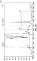
- FIG. 9B is the resulting A-Scan display 608 A of the steered ultrasonic beam 321 A detecting the notch 408 with an amplification gain of 22.5 dB.
- FIG. 9C is the resulting A-Scan display 608 B of the steered ultrasonic beam 321 B detecting the notch 408 with an amplification gain of 9 dB.
- the exemplary phased array system 200 is capable of adapting to case-specific requirements like non-standard anomaly locations and/or orientations. With the intrinsic flexibility of the phased array approach, this adaptation can be achieved by defining additional virtual probes and applying suitable electronic delay to the virtual probes, with no need for mechanical repositioning of the phased array probes.
- the method and system for inspecting a rail profile using phased array technology may result in a reduction or elimination of the need to adjust the location of the ultrasonic probes when inspecting different rail profiles, improving reflector echoes, or taking special requirements for testing into account, as the ultrasonic beams transmitted by the phased array probes can be steered to adapt to the geometry of the rail profile without mechanical adjustment of the probes.
- This adaptability reduces the need for complex mechanical systems that are prone to failure and require maintenance.
- Use of phased array probes to inspect the rail profile improves upon conventional rail profile testing systems by improving (increasing) the signal-to-noise ratio by directing the ultrasonic beam toward the defect, increasing testing sensitivity, providing highest flexibility in testing the rail profile.
- phased array evaluation techniques e.g., PaintBrush, acoustic holography
- PaintBrush acoustic holography
Abstract
Description
Claims (19)
Priority Applications (1)
| Application Number | Priority Date | Filing Date | Title |
|---|---|---|---|
| US15/873,878 US10724998B2 (en) | 2017-01-17 | 2018-01-17 | Method and system for inspecting a rail profile using phased array technology |
Applications Claiming Priority (2)
| Application Number | Priority Date | Filing Date | Title |
|---|---|---|---|
| US201762446962P | 2017-01-17 | 2017-01-17 | |
| US15/873,878 US10724998B2 (en) | 2017-01-17 | 2018-01-17 | Method and system for inspecting a rail profile using phased array technology |
Publications (2)
| Publication Number | Publication Date |
|---|---|
| US20180202977A1 US20180202977A1 (en) | 2018-07-19 |
| US10724998B2 true US10724998B2 (en) | 2020-07-28 |
Family
ID=62838219
Family Applications (1)
| Application Number | Title | Priority Date | Filing Date |
|---|---|---|---|
| US15/873,878 Active 2038-09-20 US10724998B2 (en) | 2017-01-17 | 2018-01-17 | Method and system for inspecting a rail profile using phased array technology |
Country Status (1)
| Country | Link |
|---|---|
| US (1) | US10724998B2 (en) |
Cited By (1)
| Publication number | Priority date | Publication date | Assignee | Title |
|---|---|---|---|---|
| US20220099630A1 (en) * | 2020-09-28 | 2022-03-31 | Dominick A. Pagano | Advanced highspeed system to identify and classify areas of rail anomalies |
Families Citing this family (3)
| Publication number | Priority date | Publication date | Assignee | Title |
|---|---|---|---|---|
| ES2937661T3 (en) * | 2011-08-23 | 2023-03-30 | Csir | System for monitoring the condition of structural elements and method for developing such a system |
| CN111318963B (en) * | 2020-03-09 | 2020-11-24 | 西南交通大学 | Railway track polishing amount and profile detection device |
| CN113899816B (en) * | 2021-09-10 | 2022-06-17 | 国营芜湖机械厂 | Ultrasonic nondestructive testing device and method for T-shaped composite structure and R-region testing method and device |
Citations (8)
| Publication number | Priority date | Publication date | Assignee | Title |
|---|---|---|---|---|
| US3978712A (en) * | 1971-11-17 | 1976-09-07 | Scanning Systems, Inc. | Method and apparatus for testing wear, size and residual stress conditions |
| US4662224A (en) * | 1984-03-26 | 1987-05-05 | Societe Nationale Des Chemins De Fer Francais | Process and device for the automatic recognition and detection of discontinuities and irregularities in the rails of railroad tracks |
| US4689995A (en) * | 1984-03-23 | 1987-09-01 | Societe Nationale Des Chemins De Fer Francais | Method and apparatus for the non-destructive testing of railroad track rails |
| US5777891A (en) * | 1991-05-07 | 1998-07-07 | Dapco Industries Inc | Method for real-time ultrasonic testing system |
| US20100204857A1 (en) * | 2006-09-18 | 2010-08-12 | Bombardier Transportation Gmbh | Diagnostic system and method for monitoring a rail system |
| US8820166B2 (en) * | 2011-08-22 | 2014-09-02 | Herzog Services, Inc. | Apparatus for detecting defects |
| US9010186B2 (en) * | 2008-04-23 | 2015-04-21 | Nordco Rail Services & Inspection Technologies, Inc. | Method and apparatus for detecting internal rail defects |
| US9950715B2 (en) * | 2012-04-06 | 2018-04-24 | The Regents Of The University Of California | Air-coupled ultrasonic inspection of rails |
-
2018
- 2018-01-17 US US15/873,878 patent/US10724998B2/en active Active
Patent Citations (8)
| Publication number | Priority date | Publication date | Assignee | Title |
|---|---|---|---|---|
| US3978712A (en) * | 1971-11-17 | 1976-09-07 | Scanning Systems, Inc. | Method and apparatus for testing wear, size and residual stress conditions |
| US4689995A (en) * | 1984-03-23 | 1987-09-01 | Societe Nationale Des Chemins De Fer Francais | Method and apparatus for the non-destructive testing of railroad track rails |
| US4662224A (en) * | 1984-03-26 | 1987-05-05 | Societe Nationale Des Chemins De Fer Francais | Process and device for the automatic recognition and detection of discontinuities and irregularities in the rails of railroad tracks |
| US5777891A (en) * | 1991-05-07 | 1998-07-07 | Dapco Industries Inc | Method for real-time ultrasonic testing system |
| US20100204857A1 (en) * | 2006-09-18 | 2010-08-12 | Bombardier Transportation Gmbh | Diagnostic system and method for monitoring a rail system |
| US9010186B2 (en) * | 2008-04-23 | 2015-04-21 | Nordco Rail Services & Inspection Technologies, Inc. | Method and apparatus for detecting internal rail defects |
| US8820166B2 (en) * | 2011-08-22 | 2014-09-02 | Herzog Services, Inc. | Apparatus for detecting defects |
| US9950715B2 (en) * | 2012-04-06 | 2018-04-24 | The Regents Of The University Of California | Air-coupled ultrasonic inspection of rails |
Cited By (2)
| Publication number | Priority date | Publication date | Assignee | Title |
|---|---|---|---|---|
| US20220099630A1 (en) * | 2020-09-28 | 2022-03-31 | Dominick A. Pagano | Advanced highspeed system to identify and classify areas of rail anomalies |
| US11774406B2 (en) * | 2020-09-28 | 2023-10-03 | Plasser American Corporation | Advanced highspeed system to identify and classify areas of rail anomalies |
Also Published As
| Publication number | Publication date |
|---|---|
| US20180202977A1 (en) | 2018-07-19 |
Similar Documents
| Publication | Publication Date | Title |
|---|---|---|
| US10823703B2 (en) | Real-time fusion of ultrasound and eddy current data during non-destructive examination | |
| US10724998B2 (en) | Method and system for inspecting a rail profile using phased array technology | |
| US11353430B2 (en) | Phased array probe and method for testing a spot-weld | |
| JP5795651B2 (en) | Ultrasonic immersion inspection of members with arbitrary surface contours | |
| US20040245315A1 (en) | Method and apparatus for assessing the quality of spot welds | |
| KR101163549B1 (en) | Calibration block for phased-array ultrasonic inspection | |
| US8286488B2 (en) | Apparatus and system for measuring material thickness | |
| JP2011027754A (en) | Circuit device for ultrasonic nondestructive test of test object | |
| US8746069B2 (en) | Devices and methods of ultrasound time of flight diffraction sensitivity demonstration | |
| US9347851B2 (en) | Signal processing of lamb wave data for pipe inspection | |
| JP3535417B2 (en) | Ultrasonic defect height measuring device and defect height measuring method | |
| JP2014077708A (en) | Inspection device and inspection method | |
| RU2651431C1 (en) | Method of industrial ultrasound diagnostics of vertically oriented defects of prismatic metal products and device for its implementation | |
| EP2972289B1 (en) | Ultrasonic examination of components with unknown surface geometries | |
| KR20100124238A (en) | Calibration block (reference block) and calibration procedure for phased-array ultrasonic inspection | |
| CA2012374C (en) | Ultrasonic crack sizing method | |
| Birring | Sizing Discontinuities by Ultrasonics | |
| JPH07244028A (en) | Apparatus and method for ultrasonically detecting flaw on spherical body to be detected | |
| RU2596242C1 (en) | Method for ultrasonic inspection | |
| EP4269999A1 (en) | Ultrasonic tomography method and system for evaluating pipeline corrosion | |
| Foucher et al. | Validation of the simulation software civa Ut in separated transmit/receive configurations | |
| FERNANDEZ et al. | Validation of the simulation software CIVA UT in separated transmit/receive configurations |
Legal Events
| Date | Code | Title | Description |
|---|---|---|---|
| FEPP | Fee payment procedure |
Free format text: ENTITY STATUS SET TO UNDISCOUNTED (ORIGINAL EVENT CODE: BIG.); ENTITY STATUS OF PATENT OWNER: LARGE ENTITY |
|
| AS | Assignment |
Owner name: GENERAL ELECTRIC COMPANY, NEW YORK Free format text: ASSIGNMENT OF ASSIGNORS INTEREST;ASSIGNORS:STANDOP, SEBASTIAN;CHINTA, PRASHANTH KUMAR;FUCHS, GUENTER;AND OTHERS;REEL/FRAME:044648/0832 Effective date: 20180112 |
|
| STPP | Information on status: patent application and granting procedure in general |
Free format text: DOCKETED NEW CASE - READY FOR EXAMINATION |
|
| STPP | Information on status: patent application and granting procedure in general |
Free format text: NON FINAL ACTION MAILED |
|
| STPP | Information on status: patent application and granting procedure in general |
Free format text: RESPONSE TO NON-FINAL OFFICE ACTION ENTERED AND FORWARDED TO EXAMINER |
|
| STPP | Information on status: patent application and granting procedure in general |
Free format text: NOTICE OF ALLOWANCE MAILED -- APPLICATION RECEIVED IN OFFICE OF PUBLICATIONS |
|
| AS | Assignment |
Owner name: GE GLOBAL SOURCING LLC, CONNECTICUT Free format text: ASSIGNMENT OF ASSIGNORS INTEREST;ASSIGNOR:GENERAL ELECTRIC COMPANY;REEL/FRAME:052358/0289 Effective date: 20181101 |
|
| STPP | Information on status: patent application and granting procedure in general |
Free format text: PUBLICATIONS -- ISSUE FEE PAYMENT VERIFIED |
|
| STCF | Information on status: patent grant |
Free format text: PATENTED CASE |
|
| MAFP | Maintenance fee payment |
Free format text: PAYMENT OF MAINTENANCE FEE, 4TH YEAR, LARGE ENTITY (ORIGINAL EVENT CODE: M1551); ENTITY STATUS OF PATENT OWNER: LARGE ENTITY Year of fee payment: 4 |