US10724427B2 - Method for controlling the quantity of air introduced to the intake of a supercharged internal combustion engine by a single-inlet turbocompressor - Google Patents

Method for controlling the quantity of air introduced to the intake of a supercharged internal combustion engine by a single-inlet turbocompressor Download PDF

Info

Publication number
US10724427B2
US10724427B2 US16/099,867 US201716099867A US10724427B2 US 10724427 B2 US10724427 B2 US 10724427B2 US 201716099867 A US201716099867 A US 201716099867A US 10724427 B2 US10724427 B2 US 10724427B2
Authority
US
United States
Prior art keywords
engine
stabilized
proportional valve
setting
state
Prior art date
Legal status (The legal status is an assumption and is not a legal conclusion. Google has not performed a legal analysis and makes no representation as to the accuracy of the status listed.)
Expired - Fee Related
Application number
US16/099,867
Other versions
US20190128174A1 (en
Inventor
Thierry Colliou
Jean-Marc Zaccardi
Olivier BAUDRAND
Current Assignee (The listed assignees may be inaccurate. Google has not performed a legal analysis and makes no representation or warranty as to the accuracy of the list.)
IFP Energies Nouvelles IFPEN
Original Assignee
IFP Energies Nouvelles IFPEN
Priority date (The priority date is an assumption and is not a legal conclusion. Google has not performed a legal analysis and makes no representation as to the accuracy of the date listed.)
Filing date
Publication date
Application filed by IFP Energies Nouvelles IFPEN filed Critical IFP Energies Nouvelles IFPEN
Assigned to IFP Energies Nouvelles reassignment IFP Energies Nouvelles ASSIGNMENT OF ASSIGNORS INTEREST (SEE DOCUMENT FOR DETAILS). Assignors: BAUDRAND, Olivier, COLLIOU, THIERRY, ZACCARDI, JEAN-MARC
Publication of US20190128174A1 publication Critical patent/US20190128174A1/en
Application granted granted Critical
Publication of US10724427B2 publication Critical patent/US10724427B2/en
Expired - Fee Related legal-status Critical Current
Anticipated expiration legal-status Critical

Links

Images

Classifications

    • FMECHANICAL ENGINEERING; LIGHTING; HEATING; WEAPONS; BLASTING
    • F02COMBUSTION ENGINES; HOT-GAS OR COMBUSTION-PRODUCT ENGINE PLANTS
    • F02BINTERNAL-COMBUSTION PISTON ENGINES; COMBUSTION ENGINES IN GENERAL
    • F02B37/00Engines characterised by provision of pumps driven at least for part of the time by exhaust
    • F02B37/12Control of the pumps
    • F02B37/16Control of the pumps by bypassing charging air
    • F02B37/168Control of the pumps by bypassing charging air into the exhaust conduit
    • FMECHANICAL ENGINEERING; LIGHTING; HEATING; WEAPONS; BLASTING
    • F02COMBUSTION ENGINES; HOT-GAS OR COMBUSTION-PRODUCT ENGINE PLANTS
    • F02BINTERNAL-COMBUSTION PISTON ENGINES; COMBUSTION ENGINES IN GENERAL
    • F02B37/00Engines characterised by provision of pumps driven at least for part of the time by exhaust
    • F02B37/02Gas passages between engine outlet and pump drive, e.g. reservoirs
    • F02B37/025Multiple scrolls or multiple gas passages guiding the gas to the pump drive
    • FMECHANICAL ENGINEERING; LIGHTING; HEATING; WEAPONS; BLASTING
    • F02COMBUSTION ENGINES; HOT-GAS OR COMBUSTION-PRODUCT ENGINE PLANTS
    • F02DCONTROLLING COMBUSTION ENGINES
    • F02D41/00Electrical control of supply of combustible mixture or its constituents
    • F02D41/02Circuit arrangements for generating control signals
    • F02D41/04Introducing corrections for particular operating conditions
    • F02D41/10Introducing corrections for particular operating conditions for acceleration
    • FMECHANICAL ENGINEERING; LIGHTING; HEATING; WEAPONS; BLASTING
    • F02COMBUSTION ENGINES; HOT-GAS OR COMBUSTION-PRODUCT ENGINE PLANTS
    • F02DCONTROLLING COMBUSTION ENGINES
    • F02D2250/00Engine control related to specific problems or objectives
    • F02D2250/34Control of exhaust back pressure, e.g. for turbocharged engines
    • FMECHANICAL ENGINEERING; LIGHTING; HEATING; WEAPONS; BLASTING
    • F02COMBUSTION ENGINES; HOT-GAS OR COMBUSTION-PRODUCT ENGINE PLANTS
    • F02DCONTROLLING COMBUSTION ENGINES
    • F02D41/00Electrical control of supply of combustible mixture or its constituents
    • F02D41/0002Controlling intake air
    • F02D41/0007Controlling intake air for control of turbo-charged or super-charged engines
    • YGENERAL TAGGING OF NEW TECHNOLOGICAL DEVELOPMENTS; GENERAL TAGGING OF CROSS-SECTIONAL TECHNOLOGIES SPANNING OVER SEVERAL SECTIONS OF THE IPC; TECHNICAL SUBJECTS COVERED BY FORMER USPC CROSS-REFERENCE ART COLLECTIONS [XRACs] AND DIGESTS
    • Y02TECHNOLOGIES OR APPLICATIONS FOR MITIGATION OR ADAPTATION AGAINST CLIMATE CHANGE
    • Y02TCLIMATE CHANGE MITIGATION TECHNOLOGIES RELATED TO TRANSPORTATION
    • Y02T10/00Road transport of goods or passengers
    • Y02T10/10Internal combustion engine [ICE] based vehicles
    • Y02T10/12Improving ICE efficiencies
    • Y02T10/144

Definitions

  • the present invention relates to a method for controlling a device for introducing the quantity of air into the intake of an internal combustion engine supercharged by a single-inlet turbocompressor, in particular a stationary engine or for a motor vehicle or industrial vehicle.
  • the power delivered by an internal combustion engine is dependent on the quantity of air introduced into the combustion chamber of the engine, which is itself proportional to the density of the air.
  • a single-inlet turbocompressor In the case of supercharging by a single-inlet turbocompressor, it comprises a rotary turbine, provided with a single inlet, linked by a shaft to a rotary compressor. The exhaust gases from the engine pass through the turbine which is then driven in rotation. This rotation is then transmitted to the compressor which, through its rotation, compresses the outside air before it is introduced into the combustion chamber.
  • the compressed air has a higher density which makes it possible to increase the quantity of air introduced and contained in the combustion chamber.
  • the present invention provides a remedy to the abovementioned drawbacks by virtue of being a method for controlling a device for introducing a quantity of air into the intake of a supercharged internal combustion engine which makes it possible to address all of the power demands of the engine, and in particular in transitional operating phases.
  • the present invention makes it possible to produce and manage a transfer of the compressed air from the intake to the exhaust even when the average pressure of the compressed air at the intake is lower than that of the gases at the exhaust. All that is required is for there to be phases during the operating cycle of the engine where the pressure at the intake is higher than that at the exhaust.
  • the present invention relates to a method for controlling the quantity of air introduced to the intake of a supercharged internal combustion engine, the engine comprising an exhaust gas outlet linked to an exhaust manifold, comprising a supercharging device comprising a turbocompressor with a turbine having a single inlet connected to the exhaust gas outlet and an outside air compressor, and a duct for the partial transfer of the compressed air from the compressor to the inlet of the turbine, wherein the partial transfer duct is linked to the inlet of the turbine, the duct having a proportional valve with the circulation of the compressed air being controlled in the duct during transition operating phases in accordance with the strategies applied to control of the valve which are determined according to the characteristics of the stabilized phases.
  • a non-return valve can also be disposed on the duct.
  • the compressed air circulating in the transfer duct can be heated.
  • the initial state can be a low charge state and the final stabilized state can be a high charge state.
  • the opening setting states of the valve for the initial and final stabilized states can be identical.
  • FIG. 1 illustrates an internal combustion engine having a supercharging device according to the invention
  • FIG. 2 illustrates a variant of the internal combustion engine having a supercharging device according to FIG. 1 ;
  • FIGS. 3 to 9 show examples of management strategy for the valve.
  • FIGS. 10 and 11 show examples of operation of a GMP (power train) according to the application of the present invention.
  • the internal combustion engine 10 comprises at least two cylinders, and here four cylinders referenced 121 to 124 from the left of the figure are illustrated.
  • the engine is an internal combustion engine with direct injection, notably of diesel type, but this example does not in any way rule out any other type of internal combustion engine being used to practice the invention.
  • Each cylinder comprises an intake 14 having at least one intake valve 16 , here shown with two intake valves each controlling an intake pipe 18 .
  • the intake pipes 18 flow into an intake manifold 20 fed by a duct 22 for supplying intake air, such as compressed air.
  • This cylinder also comprises a waste gas exhaust system 24 with at least one exhaust valve 26 , which here are also illustrated as two valves each controlling an exhaust pipe 28 .
  • the exhaust pipes of each cylinder are connected to flow into an exhaust manifold 30 with an exhaust gas outlet 32 .
  • This exhaust gas outlet flows to a turbocompressor 38 for the compression of the air and more particularly to an expansion turbine 40 of the turbocompressor.
  • the turbocompressor is a single-inlet turbocompressor, better known by the term “Mono Scroll” or “Single Scroll” turbocompressor.
  • This type of turbocompressor comprises the expansion turbine 40 scavenged by the exhaust gases and which is linked by a shaft 42 to rotate a compressor 44 .
  • the compressor 44 comprises a single inlet 46 for the exhaust gases which is connected to the exhaust gas outlet 32 of the manifold 30 .
  • the gas discharge 50 of the turbine 40 is conventionally connected to the exhaust line 52 of the engine.
  • the compressor 44 of the turbocompressor 38 comprises an outside air intake 54 fed by a supply duct 56 .
  • the compressed air outlet 58 of this compressor is linked to the supply duct 22 of the intake manifold 20 by a duct 60 .
  • a transfer duct 64 makes it possible to circulate a part of the compressed air outgoing from the compressor 44 to the inlet 46 of the turbine.
  • this partial transfer duct starts from the duct 60 , at a point of intersection 66 between the compressor and the supercharging air cooling radiator 62 , and then flows to the inlet 46 of the turbine at junction 70 with the exhaust gas outlet 32 .
  • This transfer duct supports the valve 74 , which is a proportional valve, controlled by control 78 .
  • This type of proportional valve makes possible controlling the flow rate of the circulation of compressed air which circulates in the transfer duct 64 .
  • the transfer duct also comprises a non-return valve 80 which prevents the circulation of the compressed air or of the exhaust gases from this duct to the compressor.
  • this valve provides another advantage of the invention since it allows for operation of the bypass system even when the average pressure in the transfer duct 64 is lower than the average pressure in the exhaust outlet 32 . It is in fact sufficient even for the pressure swings in each of these two branches to make possible an occasional pressure differential favorable to the bypass of the air from the intake to the exhaust for the bypass system to be active, and to be so even if the average pressure levels in these two branches oppose a flow from the intake to the exhaust.
  • the proportional valve 74 is controlled to open to introduce compressed air from the compressor 44 into the turbine 40 .
  • the compressed air outgoing from the compressor 44 circulates in the transfer duct 64 to leading to the exhaust gas inlet 46 of the turbine 40 and by adding a surplus of fluid to this turbine therein.
  • the turbine is passed through not only by the exhaust gases coming from the outlet 32 , but also by compressed air which is added to these gases. Because of this, the rotation of the turbine is increased, which leads to an increase in rotation of the compressor and, consequently, an increase in the pressure of the compressed air which leaves this compressor.
  • the valve 74 is controlled by the control 78 to take a quantity of compressed air into the turbine according to the supercharging needs of the engine, and in particular during the transition phases lying between two stabilized operating phases.
  • FIG. 2 which essentially comprises the same elements as those of FIG. 1 , the compressed air outgoing from the compressor 44 and circulating in the transfer duct 64 is preheated before being introduced into the turbine 40 .
  • the transfer duct 64 supports 88 to heat the compressed air which, here is a heat exchanger configured as a heating radiator, placed after the intersection 66 and the valve 74 .
  • This radiator is crossed by the compressed air which circulates in this duct while being passed through by the exhaust gases from the engine.
  • These exhaust gases originate from the discharge 50 of the turbine and are conveyed by a duct 90 to the inlet 92 of the radiator. The exhaust gases pass through this radiator, transferring the heat therein to the compressed air to then re-emerge from this radiator through the outlet 94 to be directed to the exhaust line of the engine.
  • This heated compressed air thus makes it possible to provide additional energy to the turbine which, consequently, will turn at a higher speed.
  • This high rotational speed is then transmitted to the compressor which will produce a higher compression of the outside air.
  • the operation of the engine can be considered a succession of stabilized phases (which can be more or less long) broken up by more or less abrupt transition phases.
  • the initial pre-positioning of the valve 74 is an opening setting derived from a previously completed speed/charge mapping. Furthermore, the compressed air flow rate at the inlet of the turbine is estimated by virtue of previously defined measurements and/or estimators.
  • the present invention is particularly suited for managing the transition operating phases between two stabilized operating phases.
  • “Stabilized operation” should be understood to mean a state in which either the torque demand does not vary, or the set of actuators of the engine are not modified, for example when the quantities of fuel injected are constant over time, the EGR rate remains constant, the actuator of the turbocompressor is in one and the same position, etc.
  • “transitional operation” should be understood to mean the phase during which certain actuators are activated in response to a change of the power demand from the user. It is for example possible to describe the case of a “charge-up” during which the user will ask the engine to switch from a low-charged state (little torque, little power) to a high-charged state (high torque, high power). This charge-up can be carried out either at constant engine speed, or with a simultaneous increase in the charge and the speed. It is also possible to consider the example of a “foot lift”, that is to say a more or less abrupt reduction of the torque demand. In each of these cases, the actuators of the engine must be driven in order to ensure an optimal operation of the power train (GMP).
  • GMP power train
  • the rate of compressed air diverted is therefore adjusted throughout the stabilized operating phase in order to obtain the best operating point that satisfies the desired trade-off.
  • the search for this trade-off is therefore done based on the analysis of all or some of the following measurements or estimators:
  • the valve is therefore positioned to obtain the target flow rate of diverted compressed air, corrected or not by virtue of the estimators.
  • these transitional phases can be defined as being transitional phases between two stabilized states for which the scavenging level, permitted by the proportional valve 74 , is stabilized and optimal from the point of view of the engine performance levels expected on each of these operating points.
  • the optimal control of the valve of the partial transfer duct applies a determined strategy for changing the trajectory of closure or opening of the valve in order to switch from one stabilized state to another stabilized state in optimized conditions.
  • FIG. 3 schematically illustrates the situation of transition between the points A, representative of the stabilized point before the transition phase, and B, representative of the stabilized point after the transition phase.
  • the point A can correspond for example to the start of a charge-up, and the point B to the instant from which the desired torque is reached. That can also illustrate a reduction of charge between A and B.
  • the transition phase will, for its part, be represented in the following figures which describe examples of several strategies for optimally managing the transition between the two stabilized states A and B.
  • the method for managing the transitional phases applies determined strategies comprising at least one sequence of opening (and/or of closure) of the proportional valve to obtain an optimized operation of the compressor 44 moved by the turbine 40 to switch from one stabilized state to another.
  • FIGS. 4 to 9 illustrate different examples of management of the scavenging level during the transitional phase.
  • “Scavenging level” here designates the quantities of gas introduced by the partial transfer duct 64 for compressed air into the inlet of the turbine.
  • FIG. 4 corresponds to the case of a “scavenging” cut suddenly upon starting of the transitional phase at A to position it on the setting corresponding to the stabilized operating point B. It is noted that the fact that the “scavenging” is cut suddenly does not mean that the engine reaches its second stabilized operating point B immediately.
  • FIG. 5 corresponds to the case of a “scavenging” cut gradually, substantially linearly or not, during the transitional phase.
  • FIG. 6 corresponds to the case of a chopped “scavenging” strategy during the transitional phase.
  • several sequences of opening and of closure of the proportional valve are performed between the positions of the valve during the stabilized phases A and B.
  • FIG. 7 corresponds to the case of a “scavenging” cut gradually with levels maintained during the transitional phase.
  • the choice of the method for optimal management of the proportional valve 74 during the transitional phase depends essentially on the characteristics of the starting stabilized operating point (point A) and on those of the target stabilized operating point (point B).
  • the strategy for controlling the proportional valve must be optimized to best correspond to the characteristics of the operating points of the engine (charge, speed, flow rate, richness, time spent on each operating point, etc.) and of the supercharging (spin speed, pumping guard, etc.).
  • phase 1 engine stabilized on a low-charge operating point
  • phase 2 charge-up transitional phase
  • phase 3 engine stabilized on a high-charge operating point (charge greater than that of the first, “low” charge phase).
  • the “scavenging” is active both on the first, low-charge operating point (first phase), and on the second, high-charge operating point with a level which can be different from that of the first phase according to the needs of the engine specific to this charge level. It is also envisaged to authorize the scavenging during the transitional phase, at variable levels, according to the examples illustrated previously.
  • FIG. 8 schematically illustrates the case of charge-up with a simplified management of the scavenging.
  • the scavenging is first gradually cut at the start of the transitional phase (trajectory A-A 1 ), then a level is maintained with a certain level of “scavenging” during the transitional phase (trajectory A 1 -A 2 ), and the “scavenging” is gradually increased at the end of the transitional phase (trajectory A 2 -A 3 ).
  • FIG. 9 illustrates the example in which the two stabilized phases are operated with one and the same “scavenging” level, that is to say with the same settings of the proportional valve. It is considered that only the level of closure during the transitional phase can be modified.
  • This strategy relies on 4 parameters: the scavenging cutoff delay (t 1 ), the cutoff time (i.e. the time spent with scavenging reduced or prevented, t 2 ), the delay in restarting the scavenging (t 3 ) and the “level” of cutoff.
  • the “RSS” curve corresponds to the reference operation “single supercharging reference”.
  • the “RDS” curve corresponds to a “double supercharging reference” case, an asymptotic case mentioned in this figure only for indication purposes, the scavenging system a priori allowing an engine with single supercharging to gain in performance levels but without reaching those of an engine with double supercharging.
  • the other curves correspond to an engine provided with single supercharging equipped with a partial transfer system for compressed air or so-called “scavenging” system, according to the invention.
  • the “RBE” curve (external scavenging reference) corresponds to the case allowing the scavenging continuously, that is to say, on the low-charge point, during the transitional phase, and on the high-charge point.
  • the curve “1RBE-OFF 0.01-STAB 2.0-ON 0.01” corresponds to a case where the scavenging cutoff delay is 0.01 second, the scavenging prevention time is 2.0 seconds, and the scavenging restart time is 0.01 second. It can be seen in this case that a torque “hole” appears upon the restarting of the scavenging because the scavenging was stopped for too long.
  • the curve “2RBE-OFF 0.01-STAB 0.3-ON 0.2” finally corresponds to an optimal case where the scavenging cutoff delay is 0.01 second, the scavenging prevention time is 0.2 second, and the scavenging restart time is 0.2 second.
  • this scavenging control strategy makes it possible to obtain a rapid charge-up.
  • FIG. 11 illustrates the trend of the speed of the turbine 40 .
  • the slight drop in speed can in particular be seen, corresponding to the case which prevents the scavenging for too long.

Landscapes

  • Engineering & Computer Science (AREA)
  • Chemical & Material Sciences (AREA)
  • Combustion & Propulsion (AREA)
  • Mechanical Engineering (AREA)
  • General Engineering & Computer Science (AREA)
  • Supercharger (AREA)
  • Output Control And Ontrol Of Special Type Engine (AREA)

Abstract

Control of a quantity of air introduced into an intake of a supercharged internal combustion engine which includes a proportional valve located in a partial transfer duct which controls flow of compressed air flow through the partial transfer duct into an inlet of a turbine. The proportional valve is controlled to move between open and closed positions in accordance with strategies in accordance with stabilized phases of operation of the engine. Characteristics of stabilized phases of operation of the engine are determined and are used to control circulation of the compressed air during transitions between the stabilized phases of engine operation in accordance with the determined characteristics of the stabilized phases of the engine operation. The determined characteristics are derived from a previously completed mapping of speed and charging of the supercharged engine during a previous stabilized phase.

Description

CROSS REFERENCE TO RELATED APPLICATIONS
Reference is made to PCT/EP2017/058530 filed Apr. 10, 2017, and French Application No. 16/54,191 filed May 11, 2016, which are incorporated herein by reference in their entirety.
BACKGROUND OF THE INVENTION Field of the Invention
The present invention relates to a method for controlling a device for introducing the quantity of air into the intake of an internal combustion engine supercharged by a single-inlet turbocompressor, in particular a stationary engine or for a motor vehicle or industrial vehicle.
As is widely known, the power delivered by an internal combustion engine is dependent on the quantity of air introduced into the combustion chamber of the engine, which is itself proportional to the density of the air.
Description of the Prior Art
Thus, it is the usual practice to increase this quantity of air by use of compression of the outside air before it is taken into the combustion chamber. This operation, called supercharging, can be performed in many ways, such using a turbocompressor or a driven compressor, which can be centrifugal or volumetric.
In the case of supercharging by a single-inlet turbocompressor, it comprises a rotary turbine, provided with a single inlet, linked by a shaft to a rotary compressor. The exhaust gases from the engine pass through the turbine which is then driven in rotation. This rotation is then transmitted to the compressor which, through its rotation, compresses the outside air before it is introduced into the combustion chamber.
As is better described in the French patent application No. 2 478 736, there is provided, to be able to significantly boost this quantity of compressed air into the combustion chamber of the engine, to even further increase the compression of the outside air by the compressor.
That is done more particularly by increasing the rotational speed of the turbine and therefore of the compressor.
For that, a part of the compressed air outgoing from the compressor is deflected directly into the inlet of the turbine by being mixed with the exhaust gases. This turbine is then passed through by a greater quantity of fluid (mixture of compressed air and of exhaust gases), which makes it possible to increase the rotational speed of the turbine and consequently of the compressor. This increase in speed of the compressor thus makes it possible to increase the pressure of the outside air which is compressed in the compressor and then introduced in the combustion chamber of the engine.
The compressed air has a higher density which makes it possible to increase the quantity of air introduced and contained in the combustion chamber.
This type of supercharged engine, although satisfactory, does however exhibit substantial drawbacks.
Indeed, if the flow rate of the compressed air which is taken into the inlet of the turbine is not correctly controlled, a malfunctioning of the engine can occur.
Thus, by way of example, if too great a quantity of compressed air is deflected into the inlet of the turbine, the exhaust gases entering into the turbine are cooled too much by the compressed air, and as a result a reduction of the overall efficiency of the supercharging occurs.
SUMMARY OF THE INVENTION
The present invention provides a remedy to the abovementioned drawbacks by virtue of being a method for controlling a device for introducing a quantity of air into the intake of a supercharged internal combustion engine which makes it possible to address all of the power demands of the engine, and in particular in transitional operating phases.
The present invention makes it possible to produce and manage a transfer of the compressed air from the intake to the exhaust even when the average pressure of the compressed air at the intake is lower than that of the gases at the exhaust. All that is required is for there to be phases during the operating cycle of the engine where the pressure at the intake is higher than that at the exhaust.
Thus, the present invention relates to a method for controlling the quantity of air introduced to the intake of a supercharged internal combustion engine, the engine comprising an exhaust gas outlet linked to an exhaust manifold, comprising a supercharging device comprising a turbocompressor with a turbine having a single inlet connected to the exhaust gas outlet and an outside air compressor, and a duct for the partial transfer of the compressed air from the compressor to the inlet of the turbine, wherein the partial transfer duct is linked to the inlet of the turbine, the duct having a proportional valve with the circulation of the compressed air being controlled in the duct during transition operating phases in accordance with the strategies applied to control of the valve which are determined according to the characteristics of the stabilized phases.
A non-return valve can also be disposed on the duct.
The compressed air circulating in the transfer duct can be heated.
For a control strategy, the following steps can be performed:
    • beginning with an opening setting state of the valve for an initial stabilized state,
    • the setting is reduced by a determined gradient, to a value that is maintained for a time t, and
    • the setting is increased by a determined gradient to reach the opening setting of the valve for a final stabilized state.
The initial state can be a low charge state and the final stabilized state can be a high charge state.
The opening setting states of the valve for the initial and final stabilized states can be identical.
BRIEF DESCRIPTION OF THE DRAWINGS
The other features and advantages of the invention will emerge from reading the following description, which is given in a purely illustrative and nonlimiting manner, and to which are attached:
FIG. 1 illustrates an internal combustion engine having a supercharging device according to the invention;
FIG. 2 illustrates a variant of the internal combustion engine having a supercharging device according to FIG. 1;
FIGS. 3 to 9 show examples of management strategy for the valve; and
FIGS. 10 and 11 show examples of operation of a GMP (power train) according to the application of the present invention.
DETAILED DESCRIPTION OF THE INVENTION
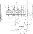
In FIG. 1, the internal combustion engine 10 comprises at least two cylinders, and here four cylinders referenced 121 to 124 from the left of the figure are illustrated.
Preferentially, the engine is an internal combustion engine with direct injection, notably of diesel type, but this example does not in any way rule out any other type of internal combustion engine being used to practice the invention.
Each cylinder comprises an intake 14 having at least one intake valve 16, here shown with two intake valves each controlling an intake pipe 18. The intake pipes 18 flow into an intake manifold 20 fed by a duct 22 for supplying intake air, such as compressed air.
This cylinder also comprises a waste gas exhaust system 24 with at least one exhaust valve 26, which here are also illustrated as two valves each controlling an exhaust pipe 28.
In the example illustrated, the exhaust pipes of each cylinder are connected to flow into an exhaust manifold 30 with an exhaust gas outlet 32. This exhaust gas outlet flows to a turbocompressor 38 for the compression of the air and more particularly to an expansion turbine 40 of the turbocompressor.
As illustrated in FIG. 1, the turbocompressor is a single-inlet turbocompressor, better known by the term “Mono Scroll” or “Single Scroll” turbocompressor.
This type of turbocompressor comprises the expansion turbine 40 scavenged by the exhaust gases and which is linked by a shaft 42 to rotate a compressor 44.
At the turbine, the compressor 44 comprises a single inlet 46 for the exhaust gases which is connected to the exhaust gas outlet 32 of the manifold 30. The gas discharge 50 of the turbine 40 is conventionally connected to the exhaust line 52 of the engine.
The compressor 44 of the turbocompressor 38 comprises an outside air intake 54 fed by a supply duct 56. The compressed air outlet 58 of this compressor is linked to the supply duct 22 of the intake manifold 20 by a duct 60.
Advantageously, provision can be made to place a compressed air cooling radiator 62 on the duct 60, between the compressor and the duct 22.
As can be seen better in FIG. 1, a transfer duct 64 makes it possible to circulate a part of the compressed air outgoing from the compressor 44 to the inlet 46 of the turbine.
More specifically, this partial transfer duct starts from the duct 60, at a point of intersection 66 between the compressor and the supercharging air cooling radiator 62, and then flows to the inlet 46 of the turbine at junction 70 with the exhaust gas outlet 32.
This transfer duct supports the valve 74, which is a proportional valve, controlled by control 78. This type of proportional valve makes possible controlling the flow rate of the circulation of compressed air which circulates in the transfer duct 64.
Advantageously, the transfer duct also comprises a non-return valve 80 which prevents the circulation of the compressed air or of the exhaust gases from this duct to the compressor.
The use of this valve provides another advantage of the invention since it allows for operation of the bypass system even when the average pressure in the transfer duct 64 is lower than the average pressure in the exhaust outlet 32. It is in fact sufficient even for the pressure swings in each of these two branches to make possible an occasional pressure differential favorable to the bypass of the air from the intake to the exhaust for the bypass system to be active, and to be so even if the average pressure levels in these two branches oppose a flow from the intake to the exhaust.
This configuration thus makes it possible, during the operation of the engine, to exploit the zones of low exhaust pressure prevailing occasionally in the exhaust manifold to introduce compressed air into the turbine and thus increase the flow rate of this turbine and consequently of the compressor, more commonly called a “Boost Turbo”. That also makes it possible to have a more effective supercharging for the low speeds and in particular to manage the transition phases with suitable proportional valve control strategies.
During operation, in a case when there is a need for large quantities of air in the cylinders, the proportional valve 74 is controlled to open to introduce compressed air from the compressor 44 into the turbine 40.
The compressed air outgoing from the compressor 44 circulates in the transfer duct 64 to leading to the exhaust gas inlet 46 of the turbine 40 and by adding a surplus of fluid to this turbine therein.
Thus, the turbine is passed through not only by the exhaust gases coming from the outlet 32, but also by compressed air which is added to these gases. Because of this, the rotation of the turbine is increased, which leads to an increase in rotation of the compressor and, consequently, an increase in the pressure of the compressed air which leaves this compressor.
The valve 74 is controlled by the control 78 to take a quantity of compressed air into the turbine according to the supercharging needs of the engine, and in particular during the transition phases lying between two stabilized operating phases.
In FIG. 2, which essentially comprises the same elements as those of FIG. 1, the compressed air outgoing from the compressor 44 and circulating in the transfer duct 64 is preheated before being introduced into the turbine 40.
For this function, the transfer duct 64 supports 88 to heat the compressed air which, here is a heat exchanger configured as a heating radiator, placed after the intersection 66 and the valve 74. This radiator is crossed by the compressed air which circulates in this duct while being passed through by the exhaust gases from the engine. These exhaust gases originate from the discharge 50 of the turbine and are conveyed by a duct 90 to the inlet 92 of the radiator. The exhaust gases pass through this radiator, transferring the heat therein to the compressed air to then re-emerge from this radiator through the outlet 94 to be directed to the exhaust line of the engine.
Thus, a part of the energy of the exhaust gases is harvested by the compressed air which is introduced into the turbine by the inlet 46.
This heated compressed air thus makes it possible to provide additional energy to the turbine which, consequently, will turn at a higher speed. This high rotational speed is then transmitted to the compressor which will produce a higher compression of the outside air.
The operation of the system described above, whether associated or not with an exhaust gas recirculation (EGR) circuit at the intake, needs to be adjusted precisely in order to produce the desired short-circuiting rate.
Generally, the operation of the engine can be considered a succession of stabilized phases (which can be more or less long) broken up by more or less abrupt transition phases.
The initial pre-positioning of the valve 74 is an opening setting derived from a previously completed speed/charge mapping. Furthermore, the compressed air flow rate at the inlet of the turbine is estimated by virtue of previously defined measurements and/or estimators.
The present invention is particularly suited for managing the transition operating phases between two stabilized operating phases.
“Stabilized operation” should be understood to mean a state in which either the torque demand does not vary, or the set of actuators of the engine are not modified, for example when the quantities of fuel injected are constant over time, the EGR rate remains constant, the actuator of the turbocompressor is in one and the same position, etc.
Conversely, “transitional operation” should be understood to mean the phase during which certain actuators are activated in response to a change of the power demand from the user. It is for example possible to describe the case of a “charge-up” during which the user will ask the engine to switch from a low-charged state (little torque, little power) to a high-charged state (high torque, high power). This charge-up can be carried out either at constant engine speed, or with a simultaneous increase in the charge and the speed. It is also possible to consider the example of a “foot lift”, that is to say a more or less abrupt reduction of the torque demand. In each of these cases, the actuators of the engine must be driven in order to ensure an optimal operation of the power train (GMP).
Thus, during the stabilized operating phases, two types of operation can be envisaged:
    • Either the position of the valve 74 corresponding to the flow rate of the initially completed mapping remains in this position as long as the charge/speed demand is unchanged.
    • Or the position of the valve 74 is adjusted throughout the period during which the engine remains in this stabilized phase. In this case, it has to be adjusted to obtain the best trade-off between:
      • the temperature at the exhaust (heating or cooling demand)
      • the richness of the exhaust (regeneration of the particulate filter FAP which makes it possible to control the oxygen ratio at the exhaust)
      • the consumption
      • the pollutant emissions
      • the dynamics requirement
      • the performance levels
The rate of compressed air diverted is therefore adjusted throughout the stabilized operating phase in order to obtain the best operating point that satisfies the desired trade-off. The search for this trade-off is therefore done based on the analysis of all or some of the following measurements or estimators:
    • the speed
    • the charge
    • the temperature at the cylinder head outlet or turbine outlet exhaust: in the case where a maximum temperature criterion is provided
    • the dynamic history (analysis of use): in the context of a highly dynamic use in which the invocations of torques are frequent or very frequent, the position of the valve 74 can be positioned to prioritize the engine response possibly momentarily to the detriment of other parameters.
    • the regeneration of the particulate filter (FAP): in the context of an FAP regeneration, the opening of the valve 74 can be prevented, even limited, in order to control the air flow rate on the FAP and not risk the runaway of the regeneration that can lead to an excessively high temperature.
    • the post-treatment temperature: in the case where the compressed air intake at the inlet of the turbine may lead to the unpriming of the post-treatment, the use thereof can be limited. However, in the case where the dynamic history shows a significant probability of the stabilized phase being followed by an increase in charge, the criterion of dynamic range may be favored.
    • engine temperature (water temperature/oil temperature)
    • the temperature of the air
    • the stabilization time: based on the time of operation of the stabilized point, the strategy of compressed air intake at the inlet of the turbine can be reviewed. For example, the dynamic history may show a highly “dynamic” operation that the time of stabilization on the point may contradict
The valve is therefore positioned to obtain the target flow rate of diverted compressed air, corrected or not by virtue of the estimators.
In addition, provision is made to optimize the dynamic range of the engine during transitional operation by controlling the opening and the closing of the valve 74 allowing the passage of the gases from the partial transfer duct for compressed air to the inlet 46 of the turbine 40.
Generally, these transitional phases can be defined as being transitional phases between two stabilized states for which the scavenging level, permitted by the proportional valve 74, is stabilized and optimal from the point of view of the engine performance levels expected on each of these operating points. The optimal control of the valve of the partial transfer duct applies a determined strategy for changing the trajectory of closure or opening of the valve in order to switch from one stabilized state to another stabilized state in optimized conditions.
FIG. 3 schematically illustrates the situation of transition between the points A, representative of the stabilized point before the transition phase, and B, representative of the stabilized point after the transition phase. The point A can correspond for example to the start of a charge-up, and the point B to the instant from which the desired torque is reached. That can also illustrate a reduction of charge between A and B. The transition phase will, for its part, be represented in the following figures which describe examples of several strategies for optimally managing the transition between the two stabilized states A and B.
In FIG. 3, “100%” and “0%” respectively mark the opening and the total closure of the passage of the gases in the valve 74. Thus, the method for managing the transitional phases applies determined strategies comprising at least one sequence of opening (and/or of closure) of the proportional valve to obtain an optimized operation of the compressor 44 moved by the turbine 40 to switch from one stabilized state to another.
FIGS. 4 to 9 illustrate different examples of management of the scavenging level during the transitional phase. “Scavenging level” here designates the quantities of gas introduced by the partial transfer duct 64 for compressed air into the inlet of the turbine.
FIG. 4 corresponds to the case of a “scavenging” cut suddenly upon starting of the transitional phase at A to position it on the setting corresponding to the stabilized operating point B. It is noted that the fact that the “scavenging” is cut suddenly does not mean that the engine reaches its second stabilized operating point B immediately.
FIG. 5 corresponds to the case of a “scavenging” cut gradually, substantially linearly or not, during the transitional phase.
FIG. 6 corresponds to the case of a chopped “scavenging” strategy during the transitional phase. Here, several sequences of opening and of closure of the proportional valve are performed between the positions of the valve during the stabilized phases A and B.
FIG. 7 corresponds to the case of a “scavenging” cut gradually with levels maintained during the transitional phase.
The choice of the method for optimal management of the proportional valve 74 during the transitional phase depends essentially on the characteristics of the starting stabilized operating point (point A) and on those of the target stabilized operating point (point B). In other words, the strategy for controlling the proportional valve must be optimized to best correspond to the characteristics of the operating points of the engine (charge, speed, flow rate, richness, time spent on each operating point, etc.) and of the supercharging (spin speed, pumping guard, etc.).
It is for example possible to describe a charge-up, that is to say a rapid increase in the demand for power to the engine. For this example, a case of transitional operation is considered with three main phases:
phase 1: engine stabilized on a low-charge operating point;
phase 2: charge-up transitional phase;
phase 3: engine stabilized on a high-charge operating point (charge greater than that of the first, “low” charge phase).
It is considered that the “scavenging” is active both on the first, low-charge operating point (first phase), and on the second, high-charge operating point with a level which can be different from that of the first phase according to the needs of the engine specific to this charge level. It is also envisaged to authorize the scavenging during the transitional phase, at variable levels, according to the examples illustrated previously.
FIG. 8 schematically illustrates the case of charge-up with a simplified management of the scavenging. Initially, the scavenging is first gradually cut at the start of the transitional phase (trajectory A-A1), then a level is maintained with a certain level of “scavenging” during the transitional phase (trajectory A1-A2), and the “scavenging” is gradually increased at the end of the transitional phase (trajectory A2-A3).
FIG. 9 illustrates the example in which the two stabilized phases are operated with one and the same “scavenging” level, that is to say with the same settings of the proportional valve. It is considered that only the level of closure during the transitional phase can be modified. This strategy relies on 4 parameters: the scavenging cutoff delay (t1), the cutoff time (i.e. the time spent with scavenging reduced or prevented, t2), the delay in restarting the scavenging (t3) and the “level” of cutoff.
The embodiments show that there is a trade-off to be found between:
a rapid restarting of the “scavenging” which can lead to a “hole” in the torque (linked to the intake/exhaust pressure balances, to the rate of residual gases, etc.);
a prolonged stoppage of the “scavenging” system which can lead to a reduction of the rotational speed of the turbine, a reduction which can then affect all the dynamics when the “scavenging” is once again authorized.
An optimal strategy hitherto identified has:
in cutting the scavenging very rapidly at the start of the transitional phase in order to obtain a rapid rise in the charge. Indeed, since the “low-charge” operating point allows the scavenging, the engine has a good richness margin for enriching the mixture rapidly and charging up (without however emitting fumes);
in then partially cutting the scavenging for a short time (approximately 0.2 to 0.3 seconds on the simulated cases) so as not to collapse the rotational speed of the turbine (a partial cutoff makes it possible a priori to retain a flow rate and maintain the turbine speed during the transitional phase);
and finally in restarting the scavenging “gently” so as to not cause the torque “hole” to appear.
This optimal strategy and other simulated cases are illustrated in FIG. 10. The “RSS” curve corresponds to the reference operation “single supercharging reference”. The “RDS” curve corresponds to a “double supercharging reference” case, an asymptotic case mentioned in this figure only for indication purposes, the scavenging system a priori allowing an engine with single supercharging to gain in performance levels but without reaching those of an engine with double supercharging.
The other curves correspond to an engine provided with single supercharging equipped with a partial transfer system for compressed air or so-called “scavenging” system, according to the invention. The “RBE” curve (external scavenging reference) corresponds to the case allowing the scavenging continuously, that is to say, on the low-charge point, during the transitional phase, and on the high-charge point.
The curve “1RBE-OFF 0.01-STAB 2.0-ON 0.01” corresponds to a case where the scavenging cutoff delay is 0.01 second, the scavenging prevention time is 2.0 seconds, and the scavenging restart time is 0.01 second. It can be seen in this case that a torque “hole” appears upon the restarting of the scavenging because the scavenging was stopped for too long.
The curve “2RBE-OFF 0.01-STAB 0.3-ON 0.2” finally corresponds to an optimal case where the scavenging cutoff delay is 0.01 second, the scavenging prevention time is 0.2 second, and the scavenging restart time is 0.2 second. As can be seen in this figure, this scavenging control strategy makes it possible to obtain a rapid charge-up.
FIG. 11 illustrates the trend of the speed of the turbine 40. The slight drop in speed can in particular be seen, corresponding to the case which prevents the scavenging for too long.
As indicated previously, the optimal control strategy varies from one engine to another, the values of the different control parameters indicated here are therefore supplied purely as an indication.

Claims (19)

The invention claimed is:
1. A method for controlling a quantity of air introduced into an intake of a supercharged internal combustion engine which includes a proportional valve located in a partial transfer duct which controls flow of compressed air flow through the partial transfer duct into an inlet of a turbine by controlling the proportional valve to move between open and closed positions in accordance with strategies which control a degree of opening of the proportional valve in accordance with stabilized phases of operation of the engine, the engine further including an exhaust gas outlet linked to an exhaust manifold, a supercharger including a turbocompressor including the turbine which has a single inlet connected to the exhaust gas outlet and to an outside air compressor and the partial transfer duct transferring compressed air flowing from the outside air compressor to the inlet of the turbine, the method comprising steps of:
determining characteristics of stabilized phases of operation of the engine and controlling circulation of the compressed air during transitions between the stabilized phases of engine operation in accordance with the determined characteristics of the stabilized phases of the engine operation; and
controlling operation of the proportional valve between a succession of stabilized phases of engine operation each spaced apart by transitional phases of operation of the engine beginning with an initial position of the proportional valve and controlling operation of the proportional valve in accordance with the determined characteristics until completion of the transitional phase which occurs upon reaching a next stabilized phase which are derived from previously completed mapping of speed and charging of the supercharged engine during a previous stabilized phase.
2. The method as claimed in claim 1, wherein the engine comprises a non-return valve disposed in the duct which prevents circulation of compressed air or exhaust gas back into the compressor.
3. The method as claimed in claim 1, comprising heating the compressed air circulating in the transfer duct.
4. The method as claimed in claim 2 comprising heating the compressed air circulating in the transfer duct.
5. The method as claimed in claim 3, comprising heating the compressed air circulating in the transfer duct by heat exchange with the exhaust gases.
6. The method as claimed in claim 4, comprising heating the compressed air circulating in the transfer duct by heat exchange with the exhaust gases.
7. The method as claimed in claim 1 comprising forming a control strategy by steps comprising:
starting engine operation from an opening setting of the proportional valve which provides an initial stabilized state of the engine operation;
reducing the opening setting of the proportional valve with a determined gradient which reduces the opening setting to a setting of the valve that is maintained for a time t; and
after time t has elapsed, increasing the opening setting of the proportional valve until reaching a setting providing a stabilized phase of the engine.
8. The method as claimed in claim 2 comprising forming a control strategy by steps of:
starting engine operation from an opening setting of the proportional valve which provides an initial stabilized state of the engine operation;
reducing the opening setting of the proportional valve with a determined gradient which reduces the opening setting to a setting of the valve that is maintained for a time t; and
after time t has elapsed, increasing the opening setting of the proportional valve until reaching a setting providing a stabilized phase of the engine.
9. The method as claimed in claim 3 comprising forming a control strategy by steps of:
starting engine operating from an opening setting of the proportional valve which provides an initial stabilized state of the engine operation;
reducing the opening setting of the proportional valve with a determined gradient which reduces the opening setting of the proportional valve to a setting of the valve that is maintained for a time t; and
after time t has elapsed, increasing the opening setting of the proportional valve until reaching a setting providing a stabilized phase of the engine.
10. The method as claimed in claim 4 comprising forming a control strategy by steps of:
starting engine operating from an opening setting of the proportional valve which provides an initial stabilized state of the engine operation;
reducing the opening setting of the proportional valve with a determined gradient which reduces the opening setting of the proportional valve to a setting of the valve that is maintained for a time t; and
after time t has elapsed, increasing the opening setting of the proportional valve until reaching a setting providing a stabilized phase of the engine.
11. The method as claimed in claim 5 comprising forming a control strategy by steps of:
starting engine operating from an opening setting of the proportional valve which provides an initial stabilized state of the engine operation;
reducing the opening setting of the proportional valve with a determined gradient which reduces the opening setting of the proportional valve to a setting of the valve that is maintained for a time t; and
after time t has elapsed, increasing the opening setting of the proportional valve until reaching a setting providing a stabilized phase of the engine.
12. The method as claimed in claim 6 comprising forming a control strategy by steps of:
starting engine operating from an opening setting of the proportional valve which provides an initial stabilized state of the engine operation;
reducing the opening setting of the proportional valve with a determined gradient which reduces the opening setting of the proportional valve to a setting of the valve that is maintained for a time t; and
after time t has elapsed, increasing the opening setting of the proportional valve until reaching a setting providing a stabilized phase of the engine.
13. The method as claimed in claim 6, wherein an initial stabilized state is a low charge state and a final stabilized state is a high charge state.
14. The method as claimed in claim 7, wherein an initial stabilized state is a low charge state and a final stabilized state is a high charge state.
15. The method as claimed in claim 8, wherein an initial stabilized state is a low charge state and a final stabilized state is a high charge state.
16. The method as claimed in claim 9, wherein an initial stabilized state is a low charge state and a final stabilized state is a high charge state.
17. The method as claimed in claim 10, wherein an initial stabilized state is a low charge state and a final stabilized state is a high charge state.
18. The method as claimed in claim 11, wherein an initial stabilized state is a low charge state and a final stabilized state is a high charge state.
19. The method as claimed in claim 12, wherein an initial stabilized state is a low charge state and a final stabilized state is a high charge state.
US16/099,867 2016-05-11 2017-04-10 Method for controlling the quantity of air introduced to the intake of a supercharged internal combustion engine by a single-inlet turbocompressor Expired - Fee Related US10724427B2 (en)

Applications Claiming Priority (3)

Application Number Priority Date Filing Date Title
FR1654191A FR3051225B1 (en) 2016-05-11 2016-05-11 METHOD OF CONTROLLING THE QUANTITY OF AIR INTRODUCED AT THE ADMISSION OF A SUPERIOR INTERNAL COMBUSTION ENGINE BY A SINGLE-INLET TURBOCHARGER
FR1654191 2016-05-11
PCT/EP2017/058530 WO2017194252A1 (en) 2016-05-11 2017-04-10 Method for controlling the quantity of air introduced to the intake of a supercharged internal combustion engine by a single-inlet turbocompressor

Publications (2)

Publication Number Publication Date
US20190128174A1 US20190128174A1 (en) 2019-05-02
US10724427B2 true US10724427B2 (en) 2020-07-28

Family

ID=56148568

Family Applications (1)

Application Number Title Priority Date Filing Date
US16/099,867 Expired - Fee Related US10724427B2 (en) 2016-05-11 2017-04-10 Method for controlling the quantity of air introduced to the intake of a supercharged internal combustion engine by a single-inlet turbocompressor

Country Status (6)

Country Link
US (1) US10724427B2 (en)
EP (1) EP3455481B1 (en)
JP (1) JP6837495B2 (en)
CN (1) CN109154244B (en)
FR (1) FR3051225B1 (en)
WO (1) WO2017194252A1 (en)

Families Citing this family (7)

* Cited by examiner, † Cited by third party
Publication number Priority date Publication date Assignee Title
US11846257B2 (en) 2021-05-03 2023-12-19 Deere & Company Engine system with reversible exhaust gas recirculation pump for controlling bypass flow
US11591992B2 (en) 2021-05-05 2023-02-28 Deere & Company Engine system with air pump for enhanced turbocharger air exchange
US11572824B2 (en) 2021-05-13 2023-02-07 Deere & Company Electrified engine boost components for mitigating engine stalling in a work vehicle
US11536213B2 (en) 2021-05-19 2022-12-27 Deere & Company Engine system with electrified air system components for managing emissions of nitrogen oxides in a work vehicle
US11572673B2 (en) 2021-06-25 2023-02-07 Deere & Company Work vehicle power system with decoupled engine air system components
US11939929B2 (en) 2021-08-19 2024-03-26 Deere &Company Engine electrified air system including electric turbocharger and exhaust gas recirculation pump
US12123379B2 (en) 2022-03-28 2024-10-22 Deere & Company Dual core exhaust gas recirculation cooler

Citations (10)

* Cited by examiner, † Cited by third party
Publication number Priority date Publication date Assignee Title
GB1140877A (en) * 1965-05-13 1969-01-22 Maschf Augsburg Nuernberg Ag Improvements in or relating to internal combustion engines
FR2478736A1 (en) 1980-03-21 1981-09-25 Semt METHOD AND SYSTEM FOR POWER GENERATION BY SUPERIOR INTERNAL COMBUSTION ENGINE
US4559784A (en) * 1979-03-14 1985-12-24 Bbc Brown, Boveri & Company, Limited Method and apparatus for regulating a bypass flow of a supercharged internal combustion engine
US5873248A (en) * 1996-06-21 1999-02-23 Caterpillar Inc. Turbocharger control system
US6058707A (en) * 1997-04-12 2000-05-09 Daimler Chrysler Ag Method of controlling the charge air mass flows of an internal combustion engine including an exhaust gas turbocharger with adjustable turbine geometry
DE10315148A1 (en) 2003-04-03 2004-11-04 Mtu Friedrichshafen Gmbh Operating supercharger for IC engine, has a compressor for compressing air and an exhaust gas turbocharger with a blower and a turbine
FR2864994A1 (en) 2004-01-12 2005-07-15 Remi Curtil Supercharged internal combustion engine e.g. diesel engine, for motor vehicle e.g. truck, has turbine admitting completely air-gas mixture, when air flow is desired, where outer wall of turbine is maintained at low temperature by air film
FR2907848A1 (en) 2006-10-31 2008-05-02 Renault Sas Internal combustion engine e.g. Diesel engine, for motor vehicle, has turbine driven by flow of gas, and communicating unit communicating with air intake pipe in downstream of compressor with gas discharge pipe in upstream of turbine
WO2015140989A1 (en) 2014-03-20 2015-09-24 日産自動車株式会社 Control device and control method for diesel engine
US20180149075A1 (en) * 2015-04-22 2018-05-31 IFP Energies Nouvelles Method of controlling the amount of air fed into the intake of a supercharged internal combustion engine

Family Cites Families (10)

* Cited by examiner, † Cited by third party
Publication number Priority date Publication date Assignee Title
JP2546428B2 (en) * 1990-10-12 1996-10-23 トヨタ自動車株式会社 Engine boost pressure controller
JP2000064844A (en) * 1998-08-12 2000-02-29 Mitsubishi Heavy Ind Ltd Supercharging device for internal combustion engine
FI119117B (en) * 2005-06-02 2008-07-31 Waertsilae Finland Oy Method and apparatus for a turbocharged piston engine
CN101245714A (en) * 2008-03-18 2008-08-20 孙敏超 Ejection air-supplying turbosupercharger
GB2504713B (en) * 2012-08-07 2017-07-12 Gm Global Tech Operations Llc Turbocharger by-pass system
US9599013B2 (en) * 2013-04-15 2017-03-21 Ford Global Technologies, Llc Direct manifold boost assist device with throttle body manifold volume isolation
US9359940B2 (en) * 2013-04-15 2016-06-07 Ford Global Technologies, Llc Direct manifold boost assist device with throttle body manifold volume isolation
KR20150029096A (en) * 2013-09-09 2015-03-18 현대중공업 주식회사 Engine system
EP3020939B1 (en) * 2013-10-11 2019-12-04 Mitsubishi Heavy Industries, Ltd. Engine system provided with intake bypass device
US9470183B2 (en) * 2014-08-12 2016-10-18 Ford Global Technologies, Llc Coordination of secondary air and blow-through air delivery

Patent Citations (13)

* Cited by examiner, † Cited by third party
Publication number Priority date Publication date Assignee Title
GB1140877A (en) * 1965-05-13 1969-01-22 Maschf Augsburg Nuernberg Ag Improvements in or relating to internal combustion engines
US4559784A (en) * 1979-03-14 1985-12-24 Bbc Brown, Boveri & Company, Limited Method and apparatus for regulating a bypass flow of a supercharged internal combustion engine
FR2478736A1 (en) 1980-03-21 1981-09-25 Semt METHOD AND SYSTEM FOR POWER GENERATION BY SUPERIOR INTERNAL COMBUSTION ENGINE
EP0038232A2 (en) 1980-03-21 1981-10-21 Societe D'etudes De Machines Thermiques S.E.M.T. Method and system of power generation by an internal-combustion engine
US4404805A (en) * 1980-03-21 1983-09-20 Societe D'etudes De Machines Thermiques S.E.M.T. Method of and system for power generation by supercharged internal combustion engine
US5873248A (en) * 1996-06-21 1999-02-23 Caterpillar Inc. Turbocharger control system
US6058707A (en) * 1997-04-12 2000-05-09 Daimler Chrysler Ag Method of controlling the charge air mass flows of an internal combustion engine including an exhaust gas turbocharger with adjustable turbine geometry
DE10315148A1 (en) 2003-04-03 2004-11-04 Mtu Friedrichshafen Gmbh Operating supercharger for IC engine, has a compressor for compressing air and an exhaust gas turbocharger with a blower and a turbine
FR2864994A1 (en) 2004-01-12 2005-07-15 Remi Curtil Supercharged internal combustion engine e.g. diesel engine, for motor vehicle e.g. truck, has turbine admitting completely air-gas mixture, when air flow is desired, where outer wall of turbine is maintained at low temperature by air film
FR2907848A1 (en) 2006-10-31 2008-05-02 Renault Sas Internal combustion engine e.g. Diesel engine, for motor vehicle, has turbine driven by flow of gas, and communicating unit communicating with air intake pipe in downstream of compressor with gas discharge pipe in upstream of turbine
WO2015140989A1 (en) 2014-03-20 2015-09-24 日産自動車株式会社 Control device and control method for diesel engine
US20170009676A1 (en) 2014-03-20 2017-01-12 Nissan Motor Co., Ltd. Control device and control method for diesel engine
US20180149075A1 (en) * 2015-04-22 2018-05-31 IFP Energies Nouvelles Method of controlling the amount of air fed into the intake of a supercharged internal combustion engine

Non-Patent Citations (1)

* Cited by examiner, † Cited by third party
Title
International Search Report for PCT/EP2017/058530, dated Jul. 4, 2017; English translation submitted herewith (7 pgs.).

Also Published As

Publication number Publication date
FR3051225A1 (en) 2017-11-17
WO2017194252A1 (en) 2017-11-16
JP6837495B2 (en) 2021-03-03
JP2019519708A (en) 2019-07-11
FR3051225B1 (en) 2019-09-13
CN109154244A (en) 2019-01-04
CN109154244B (en) 2021-06-11
EP3455481B1 (en) 2022-01-26
US20190128174A1 (en) 2019-05-02
EP3455481A1 (en) 2019-03-20

Similar Documents

Publication Publication Date Title
US10724427B2 (en) Method for controlling the quantity of air introduced to the intake of a supercharged internal combustion engine by a single-inlet turbocompressor
US10619559B2 (en) Method of controlling the amount of air fed into the intake of a supercharged internal combustion engine
CN104373200B (en) Method and system for pressurization control
RU2678926C2 (en) Method (versions) of cooling vehicle engine and vehicle cabin heating system
CN104373197B (en) Method and system for boosting rectifier control
US9726092B2 (en) Methods and systems for boost control
US10539070B2 (en) Systems and methods for a supercharged internal combustion engine with exhaust gas recirculation
CN106337724B (en) System and method for flowing a mixture of coolants to a charge air cooler
CN104373251A (en) Methods and systems for boost control
CN102852624B (en) For the method running the explosive motor with charger-air cooler
US10087803B2 (en) Method and system for an exhaust catalyst
CN102852663A (en) Method for controlling a turbocharger arrangement of an internal combustion engine, and control device
JPWO2012176286A1 (en) Control device for internal combustion engine
JP2017122425A (en) Control device of internal combustion engine with supercharger
CN101245730B (en) Homogeneous Compression Ignition Gasoline Engine Intake System for Hybrid Electric Vehicles
JP2016000971A (en) Internal combustion engine system with a supercharger
WO2008152491A1 (en) Exhaust gas recirculation system for internal combustion engine and exhaust gas recirculation system control method
JP6357902B2 (en) Engine exhaust gas recirculation method and exhaust gas recirculation device
JP2017036695A (en) Control device of diesel engine
US9435252B2 (en) Active conditioning system of a gaseous fluid intake of an internal combustion engine
JP3680537B2 (en) diesel engine
RU2537660C1 (en) Method of ice adjustment
US11480092B2 (en) Cooling apparatus for turbocharged engine
JP2014088779A (en) Control device for internal combustion engine
JP2017089390A (en) Intake device for internal combustion engine

Legal Events

Date Code Title Description
FEPP Fee payment procedure

Free format text: ENTITY STATUS SET TO UNDISCOUNTED (ORIGINAL EVENT CODE: BIG.); ENTITY STATUS OF PATENT OWNER: LARGE ENTITY

AS Assignment

Owner name: IFP ENERGIES NOUVELLES, FRANCE

Free format text: ASSIGNMENT OF ASSIGNORS INTEREST;ASSIGNORS:COLLIOU, THIERRY;ZACCARDI, JEAN-MARC;BAUDRAND, OLIVIER;SIGNING DATES FROM 20181108 TO 20181128;REEL/FRAME:047756/0092

STPP Information on status: patent application and granting procedure in general

Free format text: NON FINAL ACTION MAILED

STPP Information on status: patent application and granting procedure in general

Free format text: NOTICE OF ALLOWANCE MAILED -- APPLICATION RECEIVED IN OFFICE OF PUBLICATIONS

STPP Information on status: patent application and granting procedure in general

Free format text: PUBLICATIONS -- ISSUE FEE PAYMENT VERIFIED

STCF Information on status: patent grant

Free format text: PATENTED CASE

FEPP Fee payment procedure

Free format text: MAINTENANCE FEE REMINDER MAILED (ORIGINAL EVENT CODE: REM.); ENTITY STATUS OF PATENT OWNER: LARGE ENTITY

LAPS Lapse for failure to pay maintenance fees

Free format text: PATENT EXPIRED FOR FAILURE TO PAY MAINTENANCE FEES (ORIGINAL EVENT CODE: EXP.); ENTITY STATUS OF PATENT OWNER: LARGE ENTITY

STCH Information on status: patent discontinuation

Free format text: PATENT EXPIRED DUE TO NONPAYMENT OF MAINTENANCE FEES UNDER 37 CFR 1.362

FP Lapsed due to failure to pay maintenance fee

Effective date: 20240728