US10722804B2 - Wraparound peripheral device grip - Google Patents
Wraparound peripheral device grip Download PDFInfo
- Publication number
- US10722804B2 US10722804B2 US15/998,454 US201815998454A US10722804B2 US 10722804 B2 US10722804 B2 US 10722804B2 US 201815998454 A US201815998454 A US 201815998454A US 10722804 B2 US10722804 B2 US 10722804B2
- Authority
- US
- United States
- Prior art keywords
- peripheral device
- grip
- wraparound
- backing layer
- adhesive
- Prior art date
- Legal status (The legal status is an assumption and is not a legal conclusion. Google has not performed a legal analysis and makes no representation as to the accuracy of the status listed.)
- Active, expires
Links
- 230000002093 peripheral effect Effects 0.000 title claims abstract description 228
- 239000000463 material Substances 0.000 claims abstract description 105
- 239000010410 layer Substances 0.000 claims description 98
- 239000000853 adhesive Substances 0.000 claims description 52
- 230000001070 adhesive effect Effects 0.000 claims description 52
- 238000000034 method Methods 0.000 claims description 36
- 239000002344 surface layer Substances 0.000 claims description 22
- 239000012790 adhesive layer Substances 0.000 claims description 16
- 239000004820 Pressure-sensitive adhesive Substances 0.000 claims description 9
- 239000003082 abrasive agent Substances 0.000 claims description 7
- 230000004044 response Effects 0.000 claims description 3
- 229920001971 elastomer Polymers 0.000 abstract description 4
- HBMJWWWQQXIZIP-UHFFFAOYSA-N silicon carbide Chemical compound [Si+]#[C-] HBMJWWWQQXIZIP-UHFFFAOYSA-N 0.000 abstract description 4
- 229910010271 silicon carbide Inorganic materials 0.000 abstract description 4
- 239000000806 elastomer Substances 0.000 abstract description 3
- 239000002245 particle Substances 0.000 abstract description 3
- 229920003051 synthetic elastomer Polymers 0.000 abstract description 3
- 239000005061 synthetic rubber Substances 0.000 abstract description 3
- 238000005520 cutting process Methods 0.000 description 28
- 230000008569 process Effects 0.000 description 9
- 210000003811 finger Anatomy 0.000 description 7
- 238000010586 diagram Methods 0.000 description 6
- 238000004519 manufacturing process Methods 0.000 description 6
- 210000003813 thumb Anatomy 0.000 description 6
- 210000004247 hand Anatomy 0.000 description 4
- 230000002860 competitive effect Effects 0.000 description 3
- 230000014509 gene expression Effects 0.000 description 3
- 238000012986 modification Methods 0.000 description 3
- 230000004048 modification Effects 0.000 description 3
- 239000000758 substrate Substances 0.000 description 3
- 230000009471 action Effects 0.000 description 2
- 230000008901 benefit Effects 0.000 description 2
- 238000010276 construction Methods 0.000 description 2
- 230000006870 function Effects 0.000 description 2
- 230000000670 limiting effect Effects 0.000 description 2
- 239000004033 plastic Substances 0.000 description 2
- 229920001296 polysiloxane Polymers 0.000 description 2
- 230000002829 reductive effect Effects 0.000 description 2
- 238000000926 separation method Methods 0.000 description 2
- 238000013519 translation Methods 0.000 description 2
- 239000003190 viscoelastic substance Substances 0.000 description 2
- 239000011800 void material Substances 0.000 description 2
- 229910009445 Y1-Ym Inorganic materials 0.000 description 1
- 238000005299 abrasion Methods 0.000 description 1
- 238000007792 addition Methods 0.000 description 1
- 238000013459 approach Methods 0.000 description 1
- 239000011248 coating agent Substances 0.000 description 1
- 238000000576 coating method Methods 0.000 description 1
- 239000002131 composite material Substances 0.000 description 1
- 230000006378 damage Effects 0.000 description 1
- 229910001651 emery Inorganic materials 0.000 description 1
- 239000002783 friction material Substances 0.000 description 1
- 239000002223 garnet Substances 0.000 description 1
- 238000003698 laser cutting Methods 0.000 description 1
- 238000013507 mapping Methods 0.000 description 1
- TWNQGVIAIRXVLR-UHFFFAOYSA-N oxo(oxoalumanyloxy)alumane Chemical compound O=[Al]O[Al]=O TWNQGVIAIRXVLR-UHFFFAOYSA-N 0.000 description 1
- 230000036961 partial effect Effects 0.000 description 1
- 229920000728 polyester Polymers 0.000 description 1
- 239000011148 porous material Substances 0.000 description 1
- 238000003825 pressing Methods 0.000 description 1
- 238000012545 processing Methods 0.000 description 1
- 230000001681 protective effect Effects 0.000 description 1
- 239000005060 rubber Substances 0.000 description 1
- 239000000126 substance Substances 0.000 description 1
- 210000004243 sweat Anatomy 0.000 description 1
Images


Classifications
-
- B—PERFORMING OPERATIONS; TRANSPORTING
- B32—LAYERED PRODUCTS
- B32B—LAYERED PRODUCTS, i.e. PRODUCTS BUILT-UP OF STRATA OF FLAT OR NON-FLAT, e.g. CELLULAR OR HONEYCOMB, FORM
- B32B27/00—Layered products comprising a layer of synthetic resin
- B32B27/36—Layered products comprising a layer of synthetic resin comprising polyesters
-
- A—HUMAN NECESSITIES
- A63—SPORTS; GAMES; AMUSEMENTS
- A63F—CARD, BOARD, OR ROULETTE GAMES; INDOOR GAMES USING SMALL MOVING PLAYING BODIES; VIDEO GAMES; GAMES NOT OTHERWISE PROVIDED FOR
- A63F13/00—Video games, i.e. games using an electronically generated display having two or more dimensions
- A63F13/90—Constructional details or arrangements of video game devices not provided for in groups A63F13/20 or A63F13/25, e.g. housing, wiring, connections or cabinets
- A63F13/98—Accessories, i.e. detachable arrangements optional for the use of the video game device, e.g. grip supports of game controllers
-
- B—PERFORMING OPERATIONS; TRANSPORTING
- B32—LAYERED PRODUCTS
- B32B—LAYERED PRODUCTS, i.e. PRODUCTS BUILT-UP OF STRATA OF FLAT OR NON-FLAT, e.g. CELLULAR OR HONEYCOMB, FORM
- B32B25/00—Layered products comprising a layer of natural or synthetic rubber
- B32B25/04—Layered products comprising a layer of natural or synthetic rubber comprising rubber as the main or only constituent of a layer, which is next to another layer of the same or of a different material
- B32B25/06—Layered products comprising a layer of natural or synthetic rubber comprising rubber as the main or only constituent of a layer, which is next to another layer of the same or of a different material of paper or cardboard
-
- B—PERFORMING OPERATIONS; TRANSPORTING
- B32—LAYERED PRODUCTS
- B32B—LAYERED PRODUCTS, i.e. PRODUCTS BUILT-UP OF STRATA OF FLAT OR NON-FLAT, e.g. CELLULAR OR HONEYCOMB, FORM
- B32B25/00—Layered products comprising a layer of natural or synthetic rubber
- B32B25/16—Layered products comprising a layer of natural or synthetic rubber comprising polydienes homopolymers or poly-halodienes homopolymers
-
- B—PERFORMING OPERATIONS; TRANSPORTING
- B32—LAYERED PRODUCTS
- B32B—LAYERED PRODUCTS, i.e. PRODUCTS BUILT-UP OF STRATA OF FLAT OR NON-FLAT, e.g. CELLULAR OR HONEYCOMB, FORM
- B32B27/00—Layered products comprising a layer of synthetic resin
- B32B27/06—Layered products comprising a layer of synthetic resin as the main or only constituent of a layer, which is next to another layer of the same or of a different material
- B32B27/10—Layered products comprising a layer of synthetic resin as the main or only constituent of a layer, which is next to another layer of the same or of a different material of paper or cardboard
-
- B—PERFORMING OPERATIONS; TRANSPORTING
- B32—LAYERED PRODUCTS
- B32B—LAYERED PRODUCTS, i.e. PRODUCTS BUILT-UP OF STRATA OF FLAT OR NON-FLAT, e.g. CELLULAR OR HONEYCOMB, FORM
- B32B29/00—Layered products comprising a layer of paper or cardboard
- B32B29/002—Layered products comprising a layer of paper or cardboard as the main or only constituent of a layer, which is next to another layer of the same or of a different material
- B32B29/005—Layered products comprising a layer of paper or cardboard as the main or only constituent of a layer, which is next to another layer of the same or of a different material next to another layer of paper or cardboard layer
-
- B—PERFORMING OPERATIONS; TRANSPORTING
- B32—LAYERED PRODUCTS
- B32B—LAYERED PRODUCTS, i.e. PRODUCTS BUILT-UP OF STRATA OF FLAT OR NON-FLAT, e.g. CELLULAR OR HONEYCOMB, FORM
- B32B3/00—Layered products comprising a layer with external or internal discontinuities or unevennesses, or a layer of non-planar form; Layered products having particular features of form
- B32B3/02—Layered products comprising a layer with external or internal discontinuities or unevennesses, or a layer of non-planar form; Layered products having particular features of form characterised by features of form at particular places, e.g. in edge regions
-
- B—PERFORMING OPERATIONS; TRANSPORTING
- B32—LAYERED PRODUCTS
- B32B—LAYERED PRODUCTS, i.e. PRODUCTS BUILT-UP OF STRATA OF FLAT OR NON-FLAT, e.g. CELLULAR OR HONEYCOMB, FORM
- B32B3/00—Layered products comprising a layer with external or internal discontinuities or unevennesses, or a layer of non-planar form; Layered products having particular features of form
- B32B3/26—Layered products comprising a layer with external or internal discontinuities or unevennesses, or a layer of non-planar form; Layered products having particular features of form characterised by a particular shape of the outline of the cross-section of a continuous layer; characterised by a layer with cavities or internal voids ; characterised by an apertured layer
- B32B3/266—Layered products comprising a layer with external or internal discontinuities or unevennesses, or a layer of non-planar form; Layered products having particular features of form characterised by a particular shape of the outline of the cross-section of a continuous layer; characterised by a layer with cavities or internal voids ; characterised by an apertured layer characterised by an apertured layer, the apertures going through the whole thickness of the layer, e.g. expanded metal, perforated layer, slit layer regular cells B32B3/12
-
- B—PERFORMING OPERATIONS; TRANSPORTING
- B32—LAYERED PRODUCTS
- B32B—LAYERED PRODUCTS, i.e. PRODUCTS BUILT-UP OF STRATA OF FLAT OR NON-FLAT, e.g. CELLULAR OR HONEYCOMB, FORM
- B32B7/00—Layered products characterised by the relation between layers; Layered products characterised by the relative orientation of features between layers, or by the relative values of a measurable parameter between layers, i.e. products comprising layers having different physical, chemical or physicochemical properties; Layered products characterised by the interconnection of layers
- B32B7/04—Interconnection of layers
- B32B7/06—Interconnection of layers permitting easy separation
-
- B—PERFORMING OPERATIONS; TRANSPORTING
- B32—LAYERED PRODUCTS
- B32B—LAYERED PRODUCTS, i.e. PRODUCTS BUILT-UP OF STRATA OF FLAT OR NON-FLAT, e.g. CELLULAR OR HONEYCOMB, FORM
- B32B7/00—Layered products characterised by the relation between layers; Layered products characterised by the relative orientation of features between layers, or by the relative values of a measurable parameter between layers, i.e. products comprising layers having different physical, chemical or physicochemical properties; Layered products characterised by the interconnection of layers
- B32B7/04—Interconnection of layers
- B32B7/12—Interconnection of layers using interposed adhesives or interposed materials with bonding properties
-
- C—CHEMISTRY; METALLURGY
- C09—DYES; PAINTS; POLISHES; NATURAL RESINS; ADHESIVES; COMPOSITIONS NOT OTHERWISE PROVIDED FOR; APPLICATIONS OF MATERIALS NOT OTHERWISE PROVIDED FOR
- C09J—ADHESIVES; NON-MECHANICAL ASPECTS OF ADHESIVE PROCESSES IN GENERAL; ADHESIVE PROCESSES NOT PROVIDED FOR ELSEWHERE; USE OF MATERIALS AS ADHESIVES
- C09J7/00—Adhesives in the form of films or foils
- C09J7/30—Adhesives in the form of films or foils characterised by the adhesive composition
- C09J7/38—Pressure-sensitive adhesives [PSA]
-
- A—HUMAN NECESSITIES
- A63—SPORTS; GAMES; AMUSEMENTS
- A63F—CARD, BOARD, OR ROULETTE GAMES; INDOOR GAMES USING SMALL MOVING PLAYING BODIES; VIDEO GAMES; GAMES NOT OTHERWISE PROVIDED FOR
- A63F2300/00—Features of games using an electronically generated display having two or more dimensions, e.g. on a television screen, showing representations related to the game
- A63F2300/10—Features of games using an electronically generated display having two or more dimensions, e.g. on a television screen, showing representations related to the game characterized by input arrangements for converting player-generated signals into game device control signals
- A63F2300/1043—Features of games using an electronically generated display having two or more dimensions, e.g. on a television screen, showing representations related to the game characterized by input arrangements for converting player-generated signals into game device control signals being characterized by constructional details
-
- B—PERFORMING OPERATIONS; TRANSPORTING
- B32—LAYERED PRODUCTS
- B32B—LAYERED PRODUCTS, i.e. PRODUCTS BUILT-UP OF STRATA OF FLAT OR NON-FLAT, e.g. CELLULAR OR HONEYCOMB, FORM
- B32B2250/00—Layers arrangement
- B32B2250/03—3 layers
-
- B—PERFORMING OPERATIONS; TRANSPORTING
- B32—LAYERED PRODUCTS
- B32B—LAYERED PRODUCTS, i.e. PRODUCTS BUILT-UP OF STRATA OF FLAT OR NON-FLAT, e.g. CELLULAR OR HONEYCOMB, FORM
- B32B2255/00—Coating on the layer surface
- B32B2255/10—Coating on the layer surface on synthetic resin layer or on natural or synthetic rubber layer
-
- B—PERFORMING OPERATIONS; TRANSPORTING
- B32—LAYERED PRODUCTS
- B32B—LAYERED PRODUCTS, i.e. PRODUCTS BUILT-UP OF STRATA OF FLAT OR NON-FLAT, e.g. CELLULAR OR HONEYCOMB, FORM
- B32B2255/00—Coating on the layer surface
- B32B2255/26—Polymeric coating
-
- B—PERFORMING OPERATIONS; TRANSPORTING
- B32—LAYERED PRODUCTS
- B32B—LAYERED PRODUCTS, i.e. PRODUCTS BUILT-UP OF STRATA OF FLAT OR NON-FLAT, e.g. CELLULAR OR HONEYCOMB, FORM
- B32B2264/00—Composition or properties of particles which form a particulate layer or are present as additives
- B32B2264/10—Inorganic particles
- B32B2264/102—Oxide or hydroxide
-
- B—PERFORMING OPERATIONS; TRANSPORTING
- B32—LAYERED PRODUCTS
- B32B—LAYERED PRODUCTS, i.e. PRODUCTS BUILT-UP OF STRATA OF FLAT OR NON-FLAT, e.g. CELLULAR OR HONEYCOMB, FORM
- B32B2264/00—Composition or properties of particles which form a particulate layer or are present as additives
- B32B2264/10—Inorganic particles
- B32B2264/107—Ceramic
-
- B—PERFORMING OPERATIONS; TRANSPORTING
- B32—LAYERED PRODUCTS
- B32B—LAYERED PRODUCTS, i.e. PRODUCTS BUILT-UP OF STRATA OF FLAT OR NON-FLAT, e.g. CELLULAR OR HONEYCOMB, FORM
- B32B2307/00—Properties of the layers or laminate
- B32B2307/50—Properties of the layers or laminate having particular mechanical properties
- B32B2307/546—Flexural strength; Flexion stiffness
-
- B—PERFORMING OPERATIONS; TRANSPORTING
- B32—LAYERED PRODUCTS
- B32B—LAYERED PRODUCTS, i.e. PRODUCTS BUILT-UP OF STRATA OF FLAT OR NON-FLAT, e.g. CELLULAR OR HONEYCOMB, FORM
- B32B2307/00—Properties of the layers or laminate
- B32B2307/50—Properties of the layers or laminate having particular mechanical properties
- B32B2307/554—Wear resistance
-
- B—PERFORMING OPERATIONS; TRANSPORTING
- B32—LAYERED PRODUCTS
- B32B—LAYERED PRODUCTS, i.e. PRODUCTS BUILT-UP OF STRATA OF FLAT OR NON-FLAT, e.g. CELLULAR OR HONEYCOMB, FORM
- B32B2307/00—Properties of the layers or laminate
- B32B2307/70—Other properties
- B32B2307/744—Non-slip, anti-slip
-
- B—PERFORMING OPERATIONS; TRANSPORTING
- B32—LAYERED PRODUCTS
- B32B—LAYERED PRODUCTS, i.e. PRODUCTS BUILT-UP OF STRATA OF FLAT OR NON-FLAT, e.g. CELLULAR OR HONEYCOMB, FORM
- B32B2307/00—Properties of the layers or laminate
- B32B2307/70—Other properties
- B32B2307/748—Releasability
-
- B—PERFORMING OPERATIONS; TRANSPORTING
- B32—LAYERED PRODUCTS
- B32B—LAYERED PRODUCTS, i.e. PRODUCTS BUILT-UP OF STRATA OF FLAT OR NON-FLAT, e.g. CELLULAR OR HONEYCOMB, FORM
- B32B2457/00—Electrical equipment
-
- C09J2201/122—
-
- C—CHEMISTRY; METALLURGY
- C09—DYES; PAINTS; POLISHES; NATURAL RESINS; ADHESIVES; COMPOSITIONS NOT OTHERWISE PROVIDED FOR; APPLICATIONS OF MATERIALS NOT OTHERWISE PROVIDED FOR
- C09J—ADHESIVES; NON-MECHANICAL ASPECTS OF ADHESIVE PROCESSES IN GENERAL; ADHESIVE PROCESSES NOT PROVIDED FOR ELSEWHERE; USE OF MATERIALS AS ADHESIVES
- C09J2301/00—Additional features of adhesives in the form of films or foils
- C09J2301/10—Additional features of adhesives in the form of films or foils characterized by the structural features of the adhesive tape or sheet
- C09J2301/12—Additional features of adhesives in the form of films or foils characterized by the structural features of the adhesive tape or sheet by the arrangement of layers
- C09J2301/122—Additional features of adhesives in the form of films or foils characterized by the structural features of the adhesive tape or sheet by the arrangement of layers the adhesive layer being present only on one side of the carrier, e.g. single-sided adhesive tape
Definitions
- the present disclosure relates generally to peripheral device grips, and more specifically, to wraparound grips for human interface control devices and methods of manufacturing the same.
- peripheral devices have been made of molded rigid plastic material.
- the exterior surface of the gripping area of such peripheral devices include smooth or semi-smooth texturing.
- conventional peripheral devices may be ergonomically designed to fit the hands of most users, many users complain of slippage of the peripheral device or limited grip during use.
- Peripheral device manufacturers have attempted to provide enhanced control by applying a texture, or an overmolded material, to one or more contact surfaces of the buttons, triggers, and/or control sticks. While this approach helps with movement or actuation of the controls it does nothing for the grip on the peripheral device itself. As can be appreciated, during long or challenging gaming sessions the hands of a competitive gamer may begin to sweat or fatigue. At this point, the may lose proper grip of the controller. This lack of grip can result in a missed movement or button actuation and in some cases even in the loss of a game.
- a wraparound peripheral device grip comprising a substantially flat sheet that, when wrapped around a peripheral device, conforms to the three-dimensional shape of the device.
- the wraparound peripheral device grip may include an adhesive layer configured to contact and adhere to an outer surface of the peripheral device. Opposite the adhesive layer is a grip layer comprising at least one textured surface. Depending on the texture, the surface may be configured to provide various levels of grip for a user.
- the textured surface may be made from a material including a grit substance that is bonded to a receiving layer. This material may be similar, if not identical, to sandpaper, silicon carbide, and/or other captured grit high-friction material.
- the textured surface may be made from a material including a formed plastic incorporating a series of ridges and valleys defining an interrupted surface across an area of the grip.
- the adhesive layer and the grip layer may be separated by an interstitial layer disposed therebetween.
- the interstitial layer may provide a cushioned or compressible portion between the adhesive layer and the grip layer.
- the interstitial layer may serve as a rigid substrate to receive the adhesive on a first side and the textured surface on an opposite side.
- the wraparound peripheral device grip may be manufactured from a substantially flat sheet material including a number of cuts or slits defining a peripheral shape of the grip.
- a substantially flat sheet material including a number of cuts or slits defining a peripheral shape of the grip.
- the substantially flat grip may bend and form to match the contour of the peripheral device at the cuts and slits. These cuts and slits allow the flat grip to be wrapped around the peripheral device without overlapping.
- the substantially flat continuous sheet may be flexible.
- the sheet may have a first side and a second side.
- the first side may include a material for adhering to a gripping area of a peripheral device and the second side may include a surface for providing improved gripping to a user of the peripheral device.
- the substantially flat continuous flexible sheet may be custom cut to fit a particular model of peripheral device.
- the wraparound peripheral device grip is capable of being placed onto the peripheral device by wrapping the wraparound peripheral device grip around the factory gripping area of the peripheral device.
- the second, or grip, side of the wraparound peripheral device grip can achieve increased friction by including abrading particles thereon (e.g., using sandpaper, silicon carbide, grit, and/or grip tape).
- the grip side can be made from an elastomer, such as a synthetic rubber, or other material with the property of viscoelasticity.
- each of the expressions “at least one of A, B and C,” “at least one of A, B, or C,” “one or more of A, B, and C,” “one or more of A, B, or C,” and “A, B, and/or C” means A alone, B alone, C alone, A and B together, A and C together, B and C together, or A, B and C together.
- each one of A, B, and C in the above expressions refers to an element, such as X, Y, and Z, or class of elements, such as X 1 -X n , Y 1 -Y m , and Z 1 -Z o
- the phrase is intended to refer to a single element selected from X, Y, and Z, a combination of elements selected from the same class (e.g., X 1 and X 2 ) as well as a combination of elements selected from two or more classes (e.g., Y 1 and Z o ).
- FIG. 1A is a cross-sectional end view of material layers of the wraparound peripheral device grip in accordance with embodiments of the present disclosure
- FIG. 1B is a plan view of a wraparound peripheral device grip in accordance with embodiments of the present disclosure
- FIG. 1C is a plan view of a wraparound peripheral device grip in a first application state onto a peripheral device in accordance with embodiments of the present disclosure
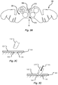
- FIG. 2 is a detail view of an area of the wraparound peripheral device grip in accordance with embodiments of the present disclosure
- FIG. 3A shows a wraparound peripheral device grip having a backing layer partially removed and being applied to a peripheral device in accordance with embodiments of the present disclosure
- FIG. 3B shows a backing layer of a wraparound peripheral device grip including an exposed portion of adhesive in accordance with embodiments of the present disclosure
- FIG. 3C shows a cross-sectional view of the exposed portion of adhesive disposed above a peripheral device in accordance with embodiments of the present disclosure
- FIG. 3D shows a cross-sectional view of the exposed portion of adhesive contacting a peripheral device in accordance with embodiments of the present disclosure
- FIG. 3E shows a wraparound peripheral device grip having a backing layer removed and being applied to a peripheral device at a first area in accordance with embodiments of the present disclosure
- FIG. 3F shows a wraparound peripheral device grip having a backing layer removed and being applied to a peripheral device at a second area in accordance with embodiments of the present disclosure
- FIG. 3G shows a wraparound peripheral device grip having a backing layer removed and being applied to a peripheral device at a third area in accordance with embodiments of the present disclosure
- FIG. 3H shows a plan view of a wraparound peripheral device grip applied to a peripheral device in accordance with embodiments of the present disclosure
- FIG. 3I shows a bottom perspective view of a wraparound peripheral device grip applied to a peripheral device in accordance with embodiments of the present disclosure
- FIG. 4A is a plan view of a wraparound peripheral device grip in a flat state in accordance with embodiments of the present disclosure
- FIG. 4B shows a backing layer of the wraparound peripheral device grip of FIG. 4A including exposed portions of adhesive in accordance with embodiments of the present disclosure
- FIG. 4C shows a perspective view of the wraparound peripheral device grip of FIG. 4A contacting a peripheral device at the exposed portions of adhesive in accordance with embodiments of the present disclosure
- FIG. 4D shows a top perspective view of the wraparound peripheral device grip of FIG. 4A applied to a peripheral device in accordance with embodiments of the present disclosure
- FIG. 4E shows a bottom perspective view of the wraparound peripheral device grip of FIG. 4A applied to a peripheral device in accordance with embodiments of the present disclosure
- FIG. 4F is a plan view of a peripheral device and control grips in accordance with embodiments of the present disclosure.
- FIG. 4G is a first perspective view of the control grips of FIG. 4F applied to the peripheral device at contact surfaces in accordance with embodiments of the present disclosure
- FIG. 4H is a second perspective view of the control grips of FIG. 4F applied to the peripheral device at contact surfaces in accordance with embodiments of the present disclosure
- FIG. 5A is a plan view of a system for manufacturing wraparound peripheral device grips from a substantially flat sheet of grip material in accordance with embodiments of the present disclosure
- FIG. 5B is an elevation view of the system of FIG. 5A ;
- FIG. 6 is a flow or process diagram depicting a method for determining a flat geometry of a grip matching a three-dimensional contour of a peripheral device in accordance with embodiments of the present disclosure
- FIG. 7 is a flow or process diagram depicting a method for manufacturing wraparound peripheral device grips in accordance with embodiments of the present disclosure.
- FIG. 8 is a flow or process diagram depicting a method for applying a wraparound peripheral device grip to a matching peripheral device in accordance with embodiments of the present disclosure.
- FIG. 1A a cross-sectional end view of material layers of the wraparound peripheral device grip are shown in accordance with embodiments of the present disclosure.
- one or more layers of adhesive backed materials may be used to create the wraparound peripheral device grip 100 .
- the wraparound peripheral device grip 100 may be configured to fit any peripheral device 130 and/or controller including a three-dimensional geometry. More specifically, the wraparound peripheral device grip 100 is configured to wrap around various surfaces of a three-dimensional device and provide multiple grip areas for the hands of an engaging user.
- the material 120 of the wraparound peripheral device grip 100 may include a substrate layer 124 .
- the substrate layer 124 may be made from paper or a similar flat, bendable/flexible sheet.
- An abrasive/gripping material side 122 of the material 120 can include a rough, abrasive surface, and/or a viscoelastic surface.
- the abrasive surface of the abrasive/gripping material side 122 achieves abrasion by including abrading particles of silicon carbide, aluminum oxide, garnet, emery, and/or some other abrasive material disposed on a surface of the material 120 .
- Suitable abrasive material includes skateboard grip tape.
- abrasive material includes using medium (80-120 grit) sandpaper and a pressure-sensitive adhesive applied to the smooth side of the sandpaper for the adhesive side 126 .
- the abrasive/gripping material side 122 may include a viscoelastic surface comprising at least one viscoelastic material.
- Suitable viscoelastic materials include any material, composite material, etc., made from an elastomer such as synthetic rubber or any other material having viscoelastic properties.
- the adhesive side 126 of the wraparound peripheral device grip 100 material 120 may include a pressure-sensitive adhesive capable of selectively and permanently adhering to a peripheral device 130 (e.g., gaming controller, etc.).
- a peripheral device 130 e.g., gaming controller, etc.
- the phrase “permanently adhering” may mean that removal of the wraparound peripheral device grip 100 from the peripheral device 130 may require substantial or considerable effort and that the grip 100 will not detach from the peripheral device 130 during ordinary usage.
- the pressure-sensitive adhesive may provide varying levels of adhesion based on a pressure applied to the material 120 .
- the pressure-sensitive adhesive may provide a tacky (e.g., low-level) adhesion between the material 120 and a contacting peripheral device that, among other things, allows the material to be removed from, or adjusted relative to, the peripheral device.
- a tacky e.g., low-level adhesion between the material 120 and a contacting peripheral device that, among other things, allows the material to be removed from, or adjusted relative to, the peripheral device.
- the pressure-sensitive adhesive may provide a permanent (e.g., high-level) adhesion between the material 120 and the contacting peripheral device that, among other things, prevents the material from being removed from, or adjusted relative to, the peripheral device (e.g., without significant deformation or destruction to the material 120 ).
- the wraparound peripheral device grip 100 may include a number of features that are arranged to engage with, or register to, portions of a particular receiving peripheral device 130 . As shown in FIGS. 1B and 1C , the wraparound peripheral device grip 100 may include a periphery or outside shape 102 representing a continuous cut in the substantially flat material 120 described above. The grip 100 may include slits 104 and cuts 108 configured to allow the flat sheet to bend and conform to a shape of a receiving device 130 without overlapping or stretching. For example, the slits 104 may be disposed at areas of the peripheral device 130 having surfaces that are raised from at least one adhered adjacent area of the grip 100 .
- the cuts 108 may be disposed at areas of the peripheral device 130 having surfaces that are sloped down, or lower, from at least one adhered adjacent area of the grip 100 . In some embodiments, these features may provide an ability for the wraparound peripheral device grip 100 to selectively conform to both concave and convex surfaces of a peripheral device 130 . It is an aspect of the present disclosure that the slits 104 and cuts 108 are arranged that, when the grip 100 is adhered to a peripheral device 130 , there may be no visible or perceptible seams between adjacent portions of the grip 100 attached. In one embodiment, the seams may be designed to be arranged at areas of the peripheral device 130 that are located apart from the digits of the hand of a user interfacing with the peripheral device 130 .
- the wraparound peripheral device grip 100 may include cutouts 112 , 116 , 118 for receiving buttons, switches, touchpads, control sticks, directional pads, areas, portions, and/or other features of the peripheral device 130 that will be uncovered by the grip 100 .
- the first cutouts 112 may be configured to surround at least a portion of one or more action buttons of a controller 130 .
- the second cutouts 116 may be configured to surround at least a portion of a control stick, directional pad, touchscreen, etc., and/or combinations thereof.
- the third cutouts 118 may be configured to surround at least a portion of selection switches, buttons, or alternative action buttons of the controller 130 .
- FIG. 2 shows a detail view of an embodiment of the wraparound peripheral device grip 100 taken from area “A” of FIG. 1C .
- the slits 104 are arranged at a portion of the device 130 such that an adhered first portion 204 of the grip 100 may be separated from a second portion 208 of the grip 100 .
- the slits 104 may allow a distance between the first and second portions 204 , 208 to separate, as shown by directional arrows “B.”
- the grip 100 may include a number of cuts 108 to allow the grip 100 to conform to various three-dimensional surfaces of a receiving peripheral device 130 .
- cuts 108 may be arranged at a portion of the device such that an adhered third portion 212 of the grip 100 may be brought closer to a fourth portion 216 of the grip 100 as the grip 100 is adhered to the three-dimensional downward sloping geometry.
- the cuts 108 may be spaced and dimensioned such that a distance between the third and fourth portions 212 , 216 may be brought closer together, but not overlapping, as shown by directional arrows “C”.
- FIG. 3A shows a first step applying the wraparound peripheral device grip 100 to a controller 130 .
- a portion of a backing layer 304 may first be peeled away, or separated, from the adhesive layer 126 of the material 120 at a center portion of the grip 100 and aligned with the features (e.g., buttons, control sticks, etc.) of the controller 130 .
- the backing layer 304 may be a protective material configured to prevent the grip 100 from accidentally adhering to objects, or itself.
- the backing layer 304 may provide a smooth, easily removable surface that contacts the adhesive of the adhesive layer, or side, 126 of the material 120 making up the grip 100 .
- the backing layer 304 may comprise a polyester, laminated, and/or smooth coated surface.
- the backing layer 304 may serve as a release liner for the grip 100 .
- the backing layer 304 may be coated with silicone or some other non-stick material. This coating allows the material 120 to be separated from the backing layer 304 with very little pull force.
- the user may apply pressure to the abrasive surface 122 side of the material 100 at an area opposite the exposed adhesive. This first pressure may positively seat the wraparound peripheral device grip 100 to the controller 130 .
- this portion of the backing layer 304 may allow for rotational alignment and/or controller feature registration with corresponding cutouts in the wraparound peripheral device grip 100 .
- FIG. 3B shows a wraparound peripheral device grip 100 including a backing layer 304 disposed across a majority of the adhesive surface 126 .
- a small portion of the backing layer 304 e.g., an alignment portion cover, etc.
- the backing layer 304 may be separated, or configured to separate, at a scored or cut line 312 in the backing layer 304 .
- FIGS. 3C-3D show partial cross-section views taken from direction “D” through the alignment portion 308 of FIG. 3B at various stages of grip 100 attachment.
- exposing the alignment portion 308 of the adhesive surface 126 allows a user to position the wraparound peripheral device grip 100 onto a surface of the controller 130 without the grip 100 permanently adhering to the controller 130 .
- the thickness of the backing layer 304 may separate the alignment portion 308 of the adhesive from contacting the controller surface.
- the user may press with a finger 316 , or other object, onto the area of the grip 100 opposite the exposed alignment portion 308 of adhesive in a direction 320 toward the controller surface.
- the material 120 should bend at this area and adhere to the controller 130 only at the defined small area of the alignment portion 308 .
- This small adhered area allows a user to at least rotationally align and/or move the grip 100 prior to removing the entire backing layer 304 permanently adhering the grip 100 in position relative to the controller 130 .
- the alignment portion 308 may allow the user to adhere the grip 100 to the controller 130 only at this reduced area, and if the alignment is incorrect, simply remove the grip 100 from being adhered at this point and attempt to align the grip 100 again. This removal of the grip 100 is made possible by the limited area of adhesive contact between the adhesive 126 of the grip 100 and the controller 130 .
- FIG. 3E shows a wraparound peripheral device grip 100 having a backing layer 304 removed and being applied to a peripheral device 130 at a first area in accordance with embodiments of the present disclosure.
- the third portion 212 of the grip 100 is adhered to a first area (e.g., at an arm, handle, or other three-dimensional protuberance) of the controller 130 and the dimension or size of the cut 108 in the flat sheet allows the fourth portion 216 of the grip 100 to be adhered next to the third portion 212 in contact with the controller 130 .
- the dimension or size of the cut 108 may cause an edge of the third portion 212 to contact or meet at an edge of the fourth portion 216 of the grip 100 without overlapping. This edge contact arrangement of the portions can provide an essentially seamless interface between areas of the grip 100 .
- the cut 108 may be dimensioned to provide a gap between the portions 212 , 216 .
- the remainder of the grip 100 on one side may be wrapped around at least one of the surfaces of the controller 130 .
- a second side may be adhered to the other side of the controller 130 .
- FIG. 3G shows a user removing the backing layer 304 from this second side of the grip 100 and wrapping the remaining unadhered portion of the grip 100 around the controller 130 . This wrapping and adhering of the second side of the grip 100 to the controller 130 may be substantially similar, if not identical, to the method of wrapping the first side of the grip 100 described above.
- FIGS. 3H and 3I show a wraparound peripheral device grip 100 applied to a peripheral device 130 in accordance with embodiments of the present disclosure.
- the installed wraparound peripheral device grip 100 provides a number of gripping surfaces on multiple sides of the controller 130 . Sections of the grip 100 that were separated by cuts 108 may be configured to meet at edges 324 without overlapping. This interface, or edge contact, may provide a substantially seamless appearance of the grip 100 attached to the controller 130 . In some embodiments, the edge contact may provide an imperceptible seam, especially to a user interfacing with the grip 100 and controller 130 .
- FIG. 4A is a plan view of a wraparound peripheral device grip 400 in a flat state in accordance with embodiments of the present disclosure.
- the material of the grip shown in FIG. 4A may be similar, if not identical, to the material 120 described in conjunction with FIGS. 1A-1C .
- the wraparound peripheral device grip 400 of FIG. 4A may include a number of features that are arranged to engage with, or register to, portions of a particular receiving peripheral device 430 (shown in FIG. 4B ).
- the wraparound peripheral device grip 400 may include a periphery or outside shape 402 representing a continuous cut in the substantially flat material 120 described above.
- the grip 400 may include a number of slits 404 and cuts 408 configured to allow the flat sheet to bend and conform to a shape of a receiving device 430 without overlapping or stretching.
- the slits 404 may be disposed at areas of the peripheral device 430 having surfaces that are raised from at least one adhered adjacent area of the grip 400 .
- the cuts 408 may be disposed at areas of the peripheral device 430 having surfaces that are slope down, or lower, from at least one adhered adjacent area of the grip 400 .
- the outside shape 402 , the cuts 404 , and the slits 408 may be arranged and/or otherwise disposed to match the contour and shape of a particular controller or peripheral device 430 .
- the wraparound peripheral device grip 400 may include cutouts 418 allowing a space to receive a touchscreen, identification label, battery compartment, etc., and/or other area of the peripheral device 430 that will be uncovered by the grip 400 .
- FIG. 4B shows a backing layer 424 of the wraparound peripheral device grip 400 of FIG. 4A including exposed portions 428 of adhesive in accordance with embodiments of the present disclosure.
- the backing layer 424 may be disposed across a majority of the adhesive surface 126 .
- the backing layer 424 may be similar, if not identical, to the backing layer 304 described above, and any description of the backing layer 304 , and/or other features of the grip 100 , above may equally correspond to the backing layer 424 and grip 400 described in conjunction with FIGS. 4A-4H .
- a small portion of the backing layer 424 may be removed exposing one or more alignment portions 428 of the adhesive surface 126 .
- the backing layer 424 may be separated, or configured to separate, at a scored or cut line on at least one side of the alignment portions 428 in the backing layer 424 .
- the wraparound peripheral device grip 400 may be positioned onto a surface of the controller 430 without the grip 400 permanently adhering to the controller 430 .
- the exposed adhesive surface at the alignment portions 428 may then be pressed against a surface of the controller 430 (similar, if not identical, to the pressing shown and described in conjunction with FIGS. 3C and 3D ).
- the material 120 should bend at this area and adhere to the controller 430 only at the defined small area of the alignment portion 428 . This small adhered area allows a user to at least rotationally align and/or move the grip 400 prior to removing the entire backing layer 424 permanently adhering the grip 400 in position relative to the controller 430 .
- the alignment portion 428 may allow the user to adhere the grip 400 to the controller 430 only at these one or more reduced areas, and if the alignment is incorrect, simply remove the grip 400 from being adhered at these points and attempt to align the grip 400 again. This removal of the grip 400 is made possible by the limited area of adhesive contact between the adhesive 126 of the grip 400 and the controller 430 . Applying the grip 400 may be similar, or identical, to the application described in conjunction with FIGS. 3A-3G .
- FIGS. 4D and 4E show a wraparound peripheral device grip 400 applied to a peripheral device 430 in accordance with embodiments of the present disclosure.
- the installed wraparound peripheral device grip 400 provides a number of gripping surfaces on multiple sides of the controller 430 .
- Sections of the grip 400 that were separated by cuts 408 may be configured to meet at edges 444 without overlapping.
- This interface, or edge contact may provide a substantially seamless appearance of the grip 400 attached to the controller 430 .
- the edge contact may provide an imperceptible seam, especially to a user interfacing with the grip 400 and controller 430 .
- the edges 444 may define a gap between the sections of the grip 400 that are parallel or substantially parallel to one another.
- FIGS. 4F-4H show various views of control grips 450 A, 450 B that may be applied to the peripheral device 430 in accordance with embodiments of the present disclosure.
- the control grips 450 A, 450 B may be substantially flat.
- the control grips 450 A, 450 B may include a textured side including one or more grip surfaces and an adhesive layer disposed on a side opposite the textured side.
- the control grips 450 A, 450 B may be similar, if not identical, in material and/or construction to the other grips 100 , 400 described in conjunction with FIGS. 1A-4E of the present disclosure.
- control grips 450 A, 450 B may include an adhesive layer configured to attach to a receiving area or surface 448 A, 448 B of the peripheral device 430 .
- the receiving surface 448 A, 448 B may be substantially flat, planar, curved, convex, or concave.
- control grips 450 A, 450 B may include one or more removed material portions, apertures, or cutouts 454 , 458 such that a void in the control grips 450 A, 450 B is provided.
- These cutouts 454 , 458 , or voids may be configured to receive one or more buttons, control sticks, switches, or other control elements or features associated with the peripheral device 430 .
- the first control grip 450 A may include a cross-shaped cutout 454 configured to encompass or at least partially surround a directional pad when applied to the first receiving surface 448 A of the peripheral device 430 .
- the second control grip 450 B may include a number of apertures 458 configured to encompass or at least partially surround a button when applied to the second receiving surface 448 B of the peripheral device 430 .
- the cutouts 454 , 458 may provide a void through which one or more control elements or features (e.g., buttons, sticks, switches, pads, raised surfaces, etc.) may pass at least partially through when applied to the peripheral device 430 .
- the cutouts 454 , 458 may be shaped to provide clear, or unobstructed, movement of any actuating elements without contacting the control grips 450 A, 450 B.
- the cutouts 454 , 458 may be sized to provide an amount of clearance (e.g., a distance, or dimension) between any portion of the control grips 450 A, 450 B and the control elements, features, and/or actuating elements of the peripheral device.
- an amount of clearance e.g., a distance, or dimension
- control grips 450 A, 450 B may be applied to the peripheral device 430 in addition to, or separately and apart from, a peripheral device grip 430 .
- the control grips 450 A, 450 B may provide a user with a tactile surface configured to indicate a contacting portion of the peripheral device 430 by one or more fingers/thumbs.
- this tactile surface can allow a user to quickly determine whether a finger or thumb is placed on a button, directional pad, control stick, etc. or some other surface of the peripheral device 430 .
- the tactile surface of the control grips 450 A, 450 B provide a frictional surface upon which a portion of a user's finger/thumb may rest while another portion of the user's finger/thumb may simultaneously contact a control element or feature of the peripheral device 430 .
- the user can apply a slight pressure to a control element (e.g., without fully actuating the element), allowing for faster response and/or actuation time in use.
- the coefficient of friction between the user's finger/thumb and the tactile surface of the control grips 450 A, 450 B may allow a user to keep their finger/thumb biased against a control element with little effort and/or fatigue.
- FIGS. 5A and 5B show views of a system 500 for manufacturing wraparound peripheral device grips 504 from a substantially flat sheet of grip material 520 in accordance with embodiments of the present disclosure.
- the system 500 may cut any shape or configuration of grip 100 , 400 , 450 A, 450 B described herein or any, two-dimensional geometry, shape, and/or variation thereof.
- the grip material 520 may be similar, if not identical, to the material 120 described in conjunction with FIGS. 1A-1C .
- the material 120 , 520 may include a backing layer configured to contact the adhesive layer 126 .
- the backing layer may made from a material allowing easy separation from the adhesive layer 126 .
- the backing layer may be similar, if not identical, to the backing layer 304 described above, and any description of the backing layer 304 , and/or other features of the grip 100 , above may equally correspond to the backing layer and grips 504 described in conjunction with FIGS. 5A-5B .
- the material 120 , 520 may be unrolled from a roll of material 120 , 520 and laid substantially flat onto a work surface 508 or other surface of the system 500 .
- the device grips 504 may be cut from the substantially flat material 520 via one or more cutting systems 500 .
- the system 500 may include, but are in no way limited to, a laser cutting machine, a score cutter, a fixed blade cutting machine, a computer numerical controlled (CNC) machine, etc., and/or other manual, semi-automatic, or automatic cutting machine.
- the system 500 may include a computer having a processor, a memory, and at least one application configured to translate two-dimensional shape information into cutting instructions for cutting shapes of the device grips 504 from the substantially flat material 520 .
- the system 500 may include a base 532 , a work surface 508 , and a gantry 512 .
- the gantry 512 may be moveable and/or include one or more moveable components.
- the gantry 512 may be configured to move in a first linear direction 536 relative to the base 532 and/or the work surface 508 .
- the gantry 512 may be configured to support a crossbar 516 and a cutting head 524 .
- the cutting head 524 may be configured to translate in a second linear direction 544 that is orthogonal to the first linear direction 536 .
- the work surface 508 may move in a linear direction 540 relative to the base 532 .
- the work surface 508 may be configured as a belt that is indexed by rotational movement 548 at one or more rollers.
- the system 500 may instruct one or more of the gantry 512 , the work surface 508 , cutting head 524 , etc. to move in one or more of the directions 536 , 540 , 544 providing a single or combination movement.
- cutting a circular shape in the grip material 520 may include controlling translation of the cutting head 524 to move in a positive direction of the second linear direction 544 , while the gantry 512 is simultaneously controlled to move in a positive direction of the first linear direction 536 for a first 90 degrees of the circle.
- the cutting head 524 may be controlled to continue moving along the positive direction of the second linear direction 544 , while the gantry 512 is simultaneously controlled to move in a negative direction (opposite the positive direction) of the first linear direction 536 for a second 90 degrees of the circle.
- the cutting head 524 may be controlled to move in a negative direction (opposite of the positive direction) of the second linear direction 544 , while the gantry 512 is simultaneously controlled to continue moving in the negative direction of the first linear direction 536 for a third 90 degrees of the circle.
- the circular shape may then be closed by the cutting head 524 continuing to move along the negative direction of the second linear direction 544 , while the gantry 512 is simultaneously controlled to move in a positive direction (opposite the negative direction) of the first linear direction 536 for the last 90 degrees of the circle.
- the movement along the first linear direction 536 may be provided by movement of the work surface 508 (in a linear direction 540 ) rather than movement of the gantry 512 along the first linear direction 536 or in conjunction with a movement of the gantry 512 along the first linear direction 536 .
- the cutting element 528 e.g., blade, knife, etc., and/or other sharpened element
- the material 520 may be moved relative to the cutting element 528 in cutting the shapes of each device grip 504 .
- the work surface 508 may provide a holding force for maintaining a position of the material 520 on the work surface 508 during cutting operations performed by the system 500 .
- the work surface 508 may be a porous material through which a vacuum can be applied holding the material 520 to the work surface 508 .
- the work surface 508 may include an adhesive surface, portion, strip, or other surface configured to hold the material 520 in place. It is an aspect of the present disclosure that the material may be indexed out of the system 500 by selectively releasing and/or applying this holding force. In the vacuum example above, the material 520 may be indexed out of the machine by turning off the vacuum and moving the material 520 by indexing the work surface 508 .
- the vacuum may be turned off and one or more air jets, fans, or other air blasts may be directed under the material 520 .
- This directed air may provide an air cushion upon which the material 520 may float, or release, from the work surface 508 .
- FIG. 6 is a flow or process diagram depicting a method 600 for determining a flat geometry of a grip matching a three-dimensional contour of a peripheral device in accordance with embodiments of the present disclosure.
- the method 600 may be performed by a computer, scanning system, and/or other system including three-dimensional to two-dimensional mapping capabilities.
- the method 600 begins at step 604 and proceeds by determining a geometry of a peripheral device (step 608 ). Determining the geometry may include placing the peripheral device into a three-dimensional (3D) scanner, laser scanner, etc.
- a laser scanner may include the Matter and Form model MFS1V1 3D Scanner.
- the 3D scanner may be configured to measure a subject part (i.e., peripheral device, etc.), and generate a 3D image of the subject part in the form of a digital file (e.g., STL, OBJ, PLY, XYZ, STEP, IGES, etc.).
- a subject part i.e., peripheral device, etc.
- a 3D image of the subject part in the form of a digital file (e.g., STL, OBJ, PLY, XYZ, STEP, IGES, etc.).
- the method 600 continues by determining the desired grip surface areas of the peripheral device (step 612 ).
- This step may include identifying areas of the peripheral device that is contacted by a user during operation.
- Typical grip surface areas may include, but are in no way limited to, controller arms, handles, grip surfaces, palm contact surfaces, etc., and/or other three-dimensional protuberances of the peripheral device.
- the method 600 proceeds by determining areas of the peripheral device that will not be covered by any grip surface (step 616 ).
- any features, components, or elements of the peripheral device that are configured to receive input may be excluded from grip coverage. These features may include, but are in no way limited to, buttons, triggers, touchpads, control sticks, switches, touchscreens, and/or other control actuation input elements.
- a two-dimensional (2D) shape for the grip may be generated to contour to the 3D geometry of the peripheral device (step 620 ). Areas excluded from the grip surface may be excluded entirely, or where necessary, cutout of the grip material.
- the 2D shape may then be exported from the processing system (e.g., computer, processor, etc. running a translation application) as a vector graphics file (e.g., DWG, DXF, AI, EPS, etc.) for a cutting system 500 , etc. (step 624 ).
- the method 600 ends at step 628 .
- FIG. 7 is a flow or process diagram depicting a method 700 for manufacturing wraparound peripheral device grips in accordance with embodiments of the present disclosure.
- the method 700 may be performed by the system 500 described in conjunction with FIGS. 5A and 5B .
- the method 700 begins at step 704 and proceeds by receiving a graphics file (e.g., a vector graphics file, etc.) of the 2D grip shape and/or geometry (step 708 ).
- This graphics file may be equivalent to the file generated in steps 620 and 624 and as described in conjunction with FIG. 6 .
- the method 700 continues by arranging the substantially flat grip material onto the work surface of the cutting system (step 712 ).
- this arrangement may be performed by the work surface pulling the material from a roll of material disposed adjacent to the work surface.
- the work surface may apply a vacuum to the material and index in a particular direction while the vacuum is applied pulling the material from a continuous roll of material disposed adjacent to the system.
- the method 700 may continue by automatically cutting a number of grips in the grip material (step 716 ). In one embodiment, this step is performed by the cutting system translating the 2D shape information into a series of cutting steps and movements (e.g., made by actuating a cutting head of the system). Once the grips are cut (or scored) in the material, the material may be indexed out of the cutting area of the cutting system (step 720 ). This indexing may be similar, if not identical, to the indexing described in conjunction with FIGS. 5A and 5B above.
- the method 700 may continue by separating the material including the cut grips from a portion of the material not including cut grips (step 724 ).
- the material may be separated by moving a member along a scored line between the portions of the material, providing a separation force.
- the material may be separated via one or more air blasts directed to the score line or some other area of the material.
- the cut material may be held by a gripper and forcibly removed from the uncut material (e.g., the portion of material including no cut grip shapes therein).
- the method 700 ends at step 728 .
- FIG. 8 is a flow or process diagram depicting a method 800 for applying a wraparound peripheral device grip to a matching peripheral device in accordance with embodiments of the present disclosure.
- the steps shown in FIG. 8 may be similar, or identical, to the steps of applying the grip material described in conjunction with FIGS. 3A-4E .
- the present disclosure in various aspects, embodiments, and/or configurations, includes components, methods, processes, systems and/or apparatus substantially as depicted and described herein, including various aspects, embodiments, configurations embodiments, subcombinations, and/or subsets thereof.
- the present disclosure in various aspects, embodiments, and/or configurations, includes providing devices and processes in the absence of items not depicted and/or described herein or in various aspects, embodiments, and/or configurations hereof, including in the absence of such items as may have been used in previous devices or processes, e.g., for improving performance, achieving ease and/or reducing cost of implementation.
- Embodiments include a wraparound peripheral device grip, comprising: a substantially flat continuous flexible sheet having a first side and a second side, the first side for adhering to a gripping area of a peripheral device and the second side for providing improved gripping to a user of the peripheral device, the substantially flat continuous flexible sheet cut to fit a model of the peripheral device.
- aspects of the above wraparound peripheral device grip include wherein the substantially flat continuous flexible sheet defines an area of material including a peripheral cut shape completely surrounding the area of material. Aspects of the above wraparound peripheral device grip include wherein the substantially flat continuous flexible sheet includes a first portion configured to bend out of a plane defining the substantially flat continuous flexible sheet and wrap around a majority of a curved three-dimensional protuberance of the peripheral device. Aspects of the above wraparound peripheral device grip further comprising: a backing layer attached to the first side of the substantially flat continuous flexible sheet, wherein the backing layer includes a score line passing through a majority of a thickness of the backing layer and dividing the backing layer into a first separable portion and a second separable portion.
- aspects of the above wraparound peripheral device grip include wherein the backing layer includes an alignment portion cover defined by a scored area of the backing layer, wherein the alignment portion cover is removable from the backing layer to reveal an area of adhesive on the first side of the substantially flat continuous flexible sheet.
- aspects of the above wraparound peripheral device grip include wherein the first side is completely covered with a pressure-sensitive adhesive material.
- aspects of the above wraparound peripheral device grip include wherein the second side is completely covered with an abrasive material.
- aspects of the above wraparound peripheral device grip further comprising: a plurality of apertures disposed inside the area of material and passing completely through the first side and the second side of the substantially flat continuous flexible sheet.
- Embodiments include a wraparound gaming controller grip, comprising: a substantially flat continuous flexible sheet comprising: a grip surface layer having one or more gripping features disposed thereon; an adhesive surface layer disposed opposite the grip surface layer; and a backing layer in contact with the adhesive surface layer and opposite the grip surface layer; and a plurality of cuts disposed around a periphery of the wraparound gaming controller grip, wherein each cut separates adjacent portions of the substantially flat continuous flexible sheet a first distance in a flat state and a closer second distance in a contoured state.
- aspects of the above wraparound gaming controller grip include wherein the adjacent portions of the substantially flat continuous flexible sheet separated by a first cut of the plurality of cuts meet along edges of the first cut in the contoured state. Aspects of the above wraparound gaming controller grip include wherein the substantially flat continuous flexible sheet is in the contoured state when adhered to a gaming controller via the adhesive surface layer contacting a curved portion of the gaming controller. Aspects of the above wraparound gaming controller grip include wherein the backing layer is separable from the substantially flat continuous flexible sheet. Aspects of the above wraparound gaming controller grip include wherein the backing layer includes a score line passing through a majority of a thickness of the backing layer and dividing the backing layer into a first separable portion and a second separable portion.
- aspects of the above wraparound gaming controller grip include wherein the backing layer includes an alignment portion cover defined by a scored area of the backing layer, wherein the alignment portion cover is removable from the backing layer and the adhesive surface layer to reveal an area of adhesive associated with the adhesive surface layer.
- aspects of the above wraparound gaming controller grip include wherein the grip surface layer is completely covered with an abrasive material, and wherein the adhesive surface layer is completely covered with a pressure-sensitive adhesive material.
- aspects of the above wraparound gaming controller grip further comprising: a plurality of control element apertures disposed inside the area of material and passing completely through the first side and the second side of the substantially flat continuous flexible sheet.
- Embodiments include a method of applying a wraparound peripheral device grip to a peripheral device, comprising: removing a first backing layer portion completely from a backing layer of the wraparound peripheral device grip, wherein the backing layer substantially covers an area of an adhesive layer of the wraparound peripheral device grip, and wherein removal of the first backing layer portion exposes an adhesive portion located near a center of the wraparound peripheral device grip; placing the backing layer of the wraparound peripheral device grip onto a surface of the peripheral device, wherein the exposed adhesive portion is offset from the surface of the peripheral device by a thickness of the backing layer such that the wraparound peripheral device grip does not adhere to the peripheral device; aligning the wraparound peripheral device grip to one or more features of the peripheral device; and applying, in response to aligning the wraparound peripheral device grip to the peripheral device, a contact pressure to a side of the wraparound peripheral device grip opposite the exposed adhesive portion moving the exposed adhesive portion into contact with the surface of the peripheral device such that the wraparound peripheral device grip is adhered to the peripheral device at the adhesive portion.
- aspects of the above method further comprising: removing an entirety of a first half of the backing layer exposing half of the adhesive layer of a first side of the wraparound peripheral device grip; and wrapping the first side of the wraparound peripheral device grip around a first contoured portion of the peripheral device.
- aspects of the above method further comprising: removing an entirety of a second half of the backing layer exposing a remaining half of the adhesive layer of a second side of the wraparound peripheral device grip; and wrapping the second side of the wraparound peripheral device grip around a second contoured portion of the peripheral device
- Embodiments include a method of manufacturing a wraparound peripheral device grip, comprising: cutting, via a cutting system, through multiple layers of a substantially flat continuous flexible sheet, wherein the sheet includes a plurality of layers including a grip surface layer disposed above an adhesive surface layer disposed above a backing layer along a two-dimensional outline of a peripheral device grip; wherein the two-dimensional outline of a peripheral device grip is configured to fit a model of the peripheral device when bent from a flat state into a contoured state.
Abstract
Description
Claims (17)
Priority Applications (1)
| Application Number | Priority Date | Filing Date | Title |
|---|---|---|---|
| US15/998,454 US10722804B2 (en) | 2017-08-15 | 2018-08-15 | Wraparound peripheral device grip |
Applications Claiming Priority (2)
| Application Number | Priority Date | Filing Date | Title |
|---|---|---|---|
| US201762545856P | 2017-08-15 | 2017-08-15 | |
| US15/998,454 US10722804B2 (en) | 2017-08-15 | 2018-08-15 | Wraparound peripheral device grip |
Publications (2)
| Publication Number | Publication Date |
|---|---|
| US20190054382A1 US20190054382A1 (en) | 2019-02-21 |
| US10722804B2 true US10722804B2 (en) | 2020-07-28 |
Family
ID=65360077
Family Applications (1)
| Application Number | Title | Priority Date | Filing Date |
|---|---|---|---|
| US15/998,454 Active 2038-10-13 US10722804B2 (en) | 2017-08-15 | 2018-08-15 | Wraparound peripheral device grip |
Country Status (1)
| Country | Link |
|---|---|
| US (1) | US10722804B2 (en) |
Families Citing this family (14)
| Publication number | Priority date | Publication date | Assignee | Title |
|---|---|---|---|---|
| US10722804B2 (en) * | 2017-08-15 | 2020-07-28 | Gaming Grips, Inc. | Wraparound peripheral device grip |
| USD870816S1 (en) * | 2017-08-29 | 2019-12-24 | Gaming Grips, Inc. | Wraparound grip for a gaming controller |
| USD900225S1 (en) * | 2017-08-29 | 2020-10-27 | Gaming Grips, Inc. | Wraparound peripheral grip for a game controller |
| JP6703015B2 (en) * | 2018-01-16 | 2020-06-03 | 任天堂株式会社 | Case |
| USD902938S1 (en) | 2019-11-21 | 2020-11-24 | Marketing Instincts Inc. | Skin cover for a game controller |
| USD920341S1 (en) | 2019-11-21 | 2021-05-25 | Marketing Instincts Inc. | Skin cover set for a game controller |
| USD963660S1 (en) | 2019-11-21 | 2022-09-13 | Razer (Asia Pacific) Pte., Ltd | Skin cover set for a game controller |
| US11752440B2 (en) * | 2021-03-05 | 2023-09-12 | Robert D. Braiman | Grip for video game controller |
| USD1007592S1 (en) * | 2021-07-26 | 2023-12-12 | FanChun Kong | Skin cover for game console |
| USD1004703S1 (en) * | 2021-07-26 | 2023-11-14 | FanChun Kong | Skin cover for game console |
| USD1005397S1 (en) * | 2021-07-26 | 2023-11-21 | FanChun Kong | Skin cover for a game console stand |
| USD976326S1 (en) * | 2021-11-24 | 2023-01-24 | Jiarui Zhu | Joystick LED layout mat |
| US20230330546A1 (en) * | 2022-04-13 | 2023-10-19 | Davis Allen Jolly | Game Controller Handles |
| USD1015431S1 (en) * | 2022-07-04 | 2024-02-20 | Jiarui Zhu | Joystick LED layout mat |
Citations (24)
| Publication number | Priority date | Publication date | Assignee | Title |
|---|---|---|---|---|
| US20020010020A1 (en) * | 2000-04-26 | 2002-01-24 | Glen Johnson | Friction enhancing accessories for game controllers |
| US20050022924A1 (en) * | 2002-12-27 | 2005-02-03 | Blackburn James B. | Adhesive article for and method of applying a decorative finish to a phone |
| US20050075172A1 (en) * | 2003-10-02 | 2005-04-07 | Coleman Jourdon G. S. | Cover for a video game controller |
| US6923443B1 (en) * | 1998-04-14 | 2005-08-02 | Hughes, Iv Richard James-Patrick | Controller grip for a video game machine |
| US20050275165A1 (en) * | 2004-06-10 | 2005-12-15 | Saied Hussaini | Gel grip controller |
| US20060154029A1 (en) * | 2002-12-03 | 2006-07-13 | Antonini Fred A | Adhesive backed skins and grips for handheld devices |
| US20060198978A1 (en) * | 2005-02-08 | 2006-09-07 | Antonini Fred A | Elastomeric film |
| US20090162651A1 (en) * | 2005-08-02 | 2009-06-25 | World Properties, Inc. | Silicone compositions, methods of manufacture, and articles formed therefrom |
| USD640697S1 (en) | 2010-11-18 | 2011-06-28 | Steven Paul Lovoi | Game controller grip |
| USD669078S1 (en) | 2011-12-06 | 2012-10-16 | Steven Paul Lovoi | Game controller grip |
| US20140125009A1 (en) * | 2006-02-10 | 2014-05-08 | Ippasa, Llc | Method of facilitating user preference in creative design of a manual controller |
| USD708615S1 (en) | 2012-12-20 | 2014-07-08 | Bigben Interactive S.A. | Game controller |
| USD712973S1 (en) | 2013-02-19 | 2014-09-09 | Sony Computer Entertainment Inc. | Housing of controller for electronic device |
| USD730451S1 (en) | 2014-01-23 | 2015-05-26 | Ironburg Inventions Ltd. | Controller handle insert |
| USD733802S1 (en) | 2014-01-24 | 2015-07-07 | Ironburg Inventions Ltd. | Controller back panel |
| USD736860S1 (en) | 2014-08-25 | 2015-08-18 | Steven Paul Lovoi | Game controller grip |
| USD736762S1 (en) | 2014-08-25 | 2015-08-18 | Steven Paul Lovoi | Game controller grip |
| US9210819B2 (en) * | 2011-09-30 | 2015-12-08 | Otter Products, Llc | Electronic devices grip products |
| USD768786S1 (en) | 2015-08-27 | 2016-10-11 | Amazon Technologies, Inc. | Game controller |
| USD780180S1 (en) | 2016-03-02 | 2017-02-28 | Ironburg Inventions Ltd. | Games controller |
| USD787606S1 (en) | 2008-02-15 | 2017-05-23 | Evil Controllers LLC | Game controller |
| USD816674S1 (en) | 2017-02-27 | 2018-05-01 | Lu Xue Wu | Game player handle with bracket |
| US20180154252A1 (en) | 2016-12-06 | 2018-06-07 | KontrolFreek, LLC | Multilayered ergonomic grip for handheld controllers |
| US20190054382A1 (en) * | 2017-08-15 | 2019-02-21 | Gaming Grips, Inc. | Wraparound peripheral device grip |
-
2018
- 2018-08-15 US US15/998,454 patent/US10722804B2/en active Active
Patent Citations (24)
| Publication number | Priority date | Publication date | Assignee | Title |
|---|---|---|---|---|
| US6923443B1 (en) * | 1998-04-14 | 2005-08-02 | Hughes, Iv Richard James-Patrick | Controller grip for a video game machine |
| US20020010020A1 (en) * | 2000-04-26 | 2002-01-24 | Glen Johnson | Friction enhancing accessories for game controllers |
| US20060154029A1 (en) * | 2002-12-03 | 2006-07-13 | Antonini Fred A | Adhesive backed skins and grips for handheld devices |
| US20050022924A1 (en) * | 2002-12-27 | 2005-02-03 | Blackburn James B. | Adhesive article for and method of applying a decorative finish to a phone |
| US20050075172A1 (en) * | 2003-10-02 | 2005-04-07 | Coleman Jourdon G. S. | Cover for a video game controller |
| US20050275165A1 (en) * | 2004-06-10 | 2005-12-15 | Saied Hussaini | Gel grip controller |
| US20060198978A1 (en) * | 2005-02-08 | 2006-09-07 | Antonini Fred A | Elastomeric film |
| US20090162651A1 (en) * | 2005-08-02 | 2009-06-25 | World Properties, Inc. | Silicone compositions, methods of manufacture, and articles formed therefrom |
| US20140125009A1 (en) * | 2006-02-10 | 2014-05-08 | Ippasa, Llc | Method of facilitating user preference in creative design of a manual controller |
| USD787606S1 (en) | 2008-02-15 | 2017-05-23 | Evil Controllers LLC | Game controller |
| USD640697S1 (en) | 2010-11-18 | 2011-06-28 | Steven Paul Lovoi | Game controller grip |
| US9210819B2 (en) * | 2011-09-30 | 2015-12-08 | Otter Products, Llc | Electronic devices grip products |
| USD669078S1 (en) | 2011-12-06 | 2012-10-16 | Steven Paul Lovoi | Game controller grip |
| USD708615S1 (en) | 2012-12-20 | 2014-07-08 | Bigben Interactive S.A. | Game controller |
| USD712973S1 (en) | 2013-02-19 | 2014-09-09 | Sony Computer Entertainment Inc. | Housing of controller for electronic device |
| USD730451S1 (en) | 2014-01-23 | 2015-05-26 | Ironburg Inventions Ltd. | Controller handle insert |
| USD733802S1 (en) | 2014-01-24 | 2015-07-07 | Ironburg Inventions Ltd. | Controller back panel |
| USD736860S1 (en) | 2014-08-25 | 2015-08-18 | Steven Paul Lovoi | Game controller grip |
| USD736762S1 (en) | 2014-08-25 | 2015-08-18 | Steven Paul Lovoi | Game controller grip |
| USD768786S1 (en) | 2015-08-27 | 2016-10-11 | Amazon Technologies, Inc. | Game controller |
| USD780180S1 (en) | 2016-03-02 | 2017-02-28 | Ironburg Inventions Ltd. | Games controller |
| US20180154252A1 (en) | 2016-12-06 | 2018-06-07 | KontrolFreek, LLC | Multilayered ergonomic grip for handheld controllers |
| USD816674S1 (en) | 2017-02-27 | 2018-05-01 | Lu Xue Wu | Game player handle with bracket |
| US20190054382A1 (en) * | 2017-08-15 | 2019-02-21 | Gaming Grips, Inc. | Wraparound peripheral device grip |
Non-Patent Citations (8)
| Title |
|---|
| Ex Parte Quayle Action for U.S. Appl. No. 29/615,415, mailed Jun. 28, 2019. |
| Francisco, Eric "KontrolFreek's FPS Thumbsticks Work, Kind of" Kontrol Freeks FPS; available at https://www.inverse.com/article/9297-kontrolfreek-s-fps-thumbsticks-work-kind-of; posted online Dec. 16, 2015. |
| Kontrol Freek Controller Performance Grips for PS4 & Xbox One!; available at https://www.youtube.com/watch?v=Jh5galxsRWQ; posted Oct. 7, 2017. |
| Notice of Allowance for U.S. Appl. No. 29/615,415, dated Oct. 11, 2019. |
| Office Action for U.S. Appl. No. 29/615,446, dated Aug. 26, 2019. |
| Office Action for U.S. Appl. No. 29/615,446, dated Mar. 20, 2020. |
| U.S. Appl. No. 29/615,415, filed Jun. 29, 2017, Morris et al. |
| U.S. Appl. No. 29/615,446, filed Aug. 29, 2017, Morris et al. |
Also Published As
| Publication number | Publication date |
|---|---|
| US20190054382A1 (en) | 2019-02-21 |
Similar Documents
| Publication | Publication Date | Title |
|---|---|---|
| US10722804B2 (en) | Wraparound peripheral device grip | |
| US4202139A (en) | Conformable hand sanding pad | |
| US8119213B2 (en) | Elastomeric film | |
| US6557178B1 (en) | Versatile sanding glove | |
| EP2983593B1 (en) | Skin abrader | |
| WO2005026434A1 (en) | Silicone-elastomer film and method of manufacturing same | |
| US20080223385A1 (en) | Nail File | |
| TW201944932A (en) | Artificial nail having size indication | |
| US20060178676A1 (en) | Skin smoothing implement | |
| US20200275716A1 (en) | Grip improving device, system and method | |
| EP2016853A1 (en) | Underhair forming tool | |
| US5398704A (en) | French manicure templates | |
| JP3121227U (en) | Manicure aids | |
| WO2021085203A1 (en) | Thin film layer applicator | |
| US9192277B1 (en) | Squeegee apparatus | |
| JP3180707U (en) | Nail seal | |
| JP2009500186A (en) | Polishing pad that can adhere to fingers | |
| WO2019181349A1 (en) | Skin adhesive sheet | |
| JP3171961U (en) | Abrasive sheet with release paper having a tab on each of the release paper and the abrasive sheet | |
| US20220389296A1 (en) | Adhesive anti-slip pad | |
| JPH10235565A (en) | Grinding tool and grinding sheet holding tool | |
| JP3189985U (en) | Hair removal tool | |
| JP3037079U (en) | Polishing tool | |
| JP3112229U (en) | Masking material for manicure | |
| JP3145152U (en) | Nail sharpener |
Legal Events
| Date | Code | Title | Description |
|---|---|---|---|
| AS | Assignment |
Owner name: GAMING GRIPS, INC., COLORADO Free format text: ASSIGNMENT OF ASSIGNORS INTEREST;ASSIGNORS:MORRIS, MICHAEL LEE;KOZER, MICHAEL JEFFREY;REEL/FRAME:046791/0646 Effective date: 20170815 |
|
| FEPP | Fee payment procedure |
Free format text: ENTITY STATUS SET TO SMALL (ORIGINAL EVENT CODE: SMAL); ENTITY STATUS OF PATENT OWNER: SMALL ENTITY |
|
| STPP | Information on status: patent application and granting procedure in general |
Free format text: DOCKETED NEW CASE - READY FOR EXAMINATION |
|
| STPP | Information on status: patent application and granting procedure in general |
Free format text: NON FINAL ACTION MAILED |
|
| STPP | Information on status: patent application and granting procedure in general |
Free format text: RESPONSE TO NON-FINAL OFFICE ACTION ENTERED AND FORWARDED TO EXAMINER |
|
| STPP | Information on status: patent application and granting procedure in general |
Free format text: NOTICE OF ALLOWANCE MAILED -- APPLICATION RECEIVED IN OFFICE OF PUBLICATIONS |
|
| STPP | Information on status: patent application and granting procedure in general |
Free format text: PUBLICATIONS -- ISSUE FEE PAYMENT VERIFIED |
|
| STCF | Information on status: patent grant |
Free format text: PATENTED CASE |
|
| MAFP | Maintenance fee payment |
Free format text: PAYMENT OF MAINTENANCE FEE, 4TH YR, SMALL ENTITY (ORIGINAL EVENT CODE: M2551); ENTITY STATUS OF PATENT OWNER: SMALL ENTITY Year of fee payment: 4 |