US10721413B2 - Microscopy system, microscopy method, and computer readable recording medium - Google Patents
Microscopy system, microscopy method, and computer readable recording medium Download PDFInfo
- Publication number
- US10721413B2 US10721413B2 US15/996,708 US201815996708A US10721413B2 US 10721413 B2 US10721413 B2 US 10721413B2 US 201815996708 A US201815996708 A US 201815996708A US 10721413 B2 US10721413 B2 US 10721413B2
- Authority
- US
- United States
- Prior art keywords
- focused images
- focused
- image
- images
- focused image
- Prior art date
- Legal status (The legal status is an assumption and is not a legal conclusion. Google has not performed a legal analysis and makes no representation as to the accuracy of the status listed.)
- Active, expires
Links
Images


Classifications
-
- G—PHYSICS
- G02—OPTICS
- G02B—OPTICAL ELEMENTS, SYSTEMS OR APPARATUS
- G02B27/00—Optical systems or apparatus not provided for by any of the groups G02B1/00 - G02B26/00, G02B30/00
- G02B27/0075—Optical systems or apparatus not provided for by any of the groups G02B1/00 - G02B26/00, G02B30/00 with means for altering, e.g. increasing, the depth of field or depth of focus
-
- H04N5/2356—
-
- H—ELECTRICITY
- H04—ELECTRIC COMMUNICATION TECHNIQUE
- H04N—PICTORIAL COMMUNICATION, e.g. TELEVISION
- H04N23/00—Cameras or camera modules comprising electronic image sensors; Control thereof
- H04N23/70—Circuitry for compensating brightness variation in the scene
- H04N23/743—Bracketing, i.e. taking a series of images with varying exposure conditions
-
- G—PHYSICS
- G02—OPTICS
- G02B—OPTICAL ELEMENTS, SYSTEMS OR APPARATUS
- G02B21/00—Microscopes
- G02B21/36—Microscopes arranged for photographic purposes or projection purposes or digital imaging or video purposes including associated control and data processing arrangements
- G02B21/365—Control or image processing arrangements for digital or video microscopes
- G02B21/367—Control or image processing arrangements for digital or video microscopes providing an output produced by processing a plurality of individual source images, e.g. image tiling, montage, composite images, depth sectioning, image comparison
-
- G—PHYSICS
- G02—OPTICS
- G02B—OPTICAL ELEMENTS, SYSTEMS OR APPARATUS
- G02B21/00—Microscopes
- G02B21/36—Microscopes arranged for photographic purposes or projection purposes or digital imaging or video purposes including associated control and data processing arrangements
- G02B21/368—Microscopes arranged for photographic purposes or projection purposes or digital imaging or video purposes including associated control and data processing arrangements details of associated display arrangements, e.g. mounting of LCD monitor
-
- G—PHYSICS
- G06—COMPUTING OR CALCULATING; COUNTING
- G06T—IMAGE DATA PROCESSING OR GENERATION, IN GENERAL
- G06T5/00—Image enhancement or restoration
- G06T5/50—Image enhancement or restoration using two or more images, e.g. averaging or subtraction
-
- G—PHYSICS
- G06—COMPUTING OR CALCULATING; COUNTING
- G06T—IMAGE DATA PROCESSING OR GENERATION, IN GENERAL
- G06T7/00—Image analysis
- G06T7/10—Segmentation; Edge detection
- G06T7/11—Region-based segmentation
-
- G—PHYSICS
- G06—COMPUTING OR CALCULATING; COUNTING
- G06T—IMAGE DATA PROCESSING OR GENERATION, IN GENERAL
- G06T7/00—Image analysis
- G06T7/50—Depth or shape recovery
- G06T7/55—Depth or shape recovery from multiple images
- G06T7/571—Depth or shape recovery from multiple images from focus
-
- H—ELECTRICITY
- H04—ELECTRIC COMMUNICATION TECHNIQUE
- H04N—PICTORIAL COMMUNICATION, e.g. TELEVISION
- H04N23/00—Cameras or camera modules comprising electronic image sensors; Control thereof
- H04N23/58—Means for changing the camera field of view without moving the camera body, e.g. nutating or panning of optics or image sensors
-
- H—ELECTRICITY
- H04—ELECTRIC COMMUNICATION TECHNIQUE
- H04N—PICTORIAL COMMUNICATION, e.g. TELEVISION
- H04N23/00—Cameras or camera modules comprising electronic image sensors; Control thereof
- H04N23/60—Control of cameras or camera modules
- H04N23/63—Control of cameras or camera modules by using electronic viewfinders
-
- H04N5/2259—
-
- H04N5/23293—
-
- G—PHYSICS
- G06—COMPUTING OR CALCULATING; COUNTING
- G06T—IMAGE DATA PROCESSING OR GENERATION, IN GENERAL
- G06T2200/00—Indexing scheme for image data processing or generation, in general
- G06T2200/21—Indexing scheme for image data processing or generation, in general involving computational photography
-
- G—PHYSICS
- G06—COMPUTING OR CALCULATING; COUNTING
- G06T—IMAGE DATA PROCESSING OR GENERATION, IN GENERAL
- G06T2207/00—Indexing scheme for image analysis or image enhancement
- G06T2207/10—Image acquisition modality
- G06T2207/10056—Microscopic image
-
- G—PHYSICS
- G06—COMPUTING OR CALCULATING; COUNTING
- G06T—IMAGE DATA PROCESSING OR GENERATION, IN GENERAL
- G06T2207/00—Indexing scheme for image analysis or image enhancement
- G06T2207/10—Image acquisition modality
- G06T2207/10141—Special mode during image acquisition
- G06T2207/10148—Varying focus
-
- H—ELECTRICITY
- H04—ELECTRIC COMMUNICATION TECHNIQUE
- H04N—PICTORIAL COMMUNICATION, e.g. TELEVISION
- H04N23/00—Cameras or camera modules comprising electronic image sensors; Control thereof
- H04N23/60—Control of cameras or camera modules
- H04N23/67—Focus control based on electronic image sensor signals
- H04N23/676—Bracketing for image capture at varying focusing conditions
-
- H04N5/232133—
Definitions
- the present disclosure relates to a microscopy system, a microscopy method, and a computer readable recording medium.
- a method in which a search is performed in the depth direction after presence and X-Y positions of two-dimensionally overlapping structures are checked by generation of an all-focused image from Z-stack images, may be used.
- Methods of generating an all-focused image include: a method of reconstructing a multi-focused image synthesized by superimposition of Z-stack images; and a method of extracting a focused area in each of Z-stack images and synthesizing the focused areas.
- Such an all-focused image is useful for screening of plural structural arrangements present in the depth direction.
- Japanese Patent Application Laid-open No. 2014-021489 a method, in which in-focus-ness is calculated in Z-stack images, extraction candidates are selected based on in-focus-ness in the depth direction, weighting according to the in-focus-ness is executed, and synthesis is performed, is disclosed.
- a depth map is able to be generated based on a peak of in-focus-ness at each X-Y position, and a Z-position of a peak of in-focus-ness is able to be known from this depth map.
- a microscopy system includes: an imaging unit configured to capture a subject image generated by an observation optical system of a microscope, and acquire an image; a shifting unit configured to shift positions of a focal plane and a field of view of the observation optical system; an imaging control unit configured to cause the imaging unit to acquire a multi-focused image including image information in plural planes in an optical axis direction of the observation optical system, by shifting the positions of the focal plane and the field of view in one exposure period of the imaging unit; a shift amount acquisition processing unit configured to acquire a shift amount, by which the position of the field of view is shifted; an all-focused image generating unit configured to respectively generate plural all-focused images, based on plural multi-focused images respectively acquired under plural conditions where the shift amounts differ, and on blurring information of images according to the shift amounts; and a display unit configured to consecutively display the plural all-focused images generated by the all-focused image generating unit.
- FIG. 1 is a block diagram illustrating an example of a configuration of a microscopy system according to a first embodiment
- FIG. 2 is a schematic diagram illustrating an example of a configuration of a microscope device illustrated in FIG. 1 ;
- FIG. 3 is a flow chart illustrating operation of the microscopy system illustrated in FIG. 1 ;
- FIG. 4A to FIG. 4E are schematic diagrams for explanation of processing for acquisition of plural multi-focused images
- FIG. 5 is a flow chart illustrating details of processing for generation of plural all-focused images
- FIG. 6 is a schematic diagram for explanation of a setting screen for image acquisition in processing for acquisition of a multi-focused image
- FIG. 7 is a diagram illustrating an example of an all-focused image to be displayed on a display device illustrated in FIG. 1 ;
- FIG. 8 is a diagram illustrating an example of an all-focused image to be displayed on the display device illustrated in FIG. 1 ;
- FIG. 9 is a diagram illustrating an example of an all-focused image to be displayed on the display device illustrated in FIG. 1 ;
- FIG. 10 is a diagram illustrating an example of an all-focused image to be displayed on the display device illustrated in FIG. 1 ;
- FIG. 11 is a diagram illustrating an example of an all-focused image to be displayed on the display device illustrated in FIG. 1 ;
- FIG. 12 is a schematic diagram for explanation of a method for acquisition of a multi-focused image according to a first modified example of the first embodiment
- FIG. 13 is a schematic diagram for explanation of the method for acquisition of a multi-focused image according to the first modified example of the first embodiment
- FIG. 14 is a diagram illustrating an example of an all-focused image to be displayed on the display device according to a third modified example of the first embodiment
- FIG. 15 is a diagram illustrating an example of an all-focused image to be displayed on the display device according to the third modified example of the first embodiment
- FIG. 16 is a diagram illustrating an example of an all-focused image to be displayed on the display device according to the third modified example of the first embodiment
- FIG. 17 is a diagram illustrating an example of an all-focused image to be displayed on the display device according to the third modified example of the first embodiment
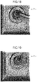
- FIG. 18 is a diagram illustrating an example of an all-focused image to be displayed on the display device according to the third modified example of the first embodiment
- FIG. 19 is a diagram illustrating an example of an all-focused image to be displayed on the display device according to the third modified example of the first embodiment
- FIG. 20 is a diagram illustrating an example of an all-focused image to be displayed on the display device according to the third modified example of the first embodiment
- FIG. 21 is a diagram illustrating an example of an all-focused image to be displayed on the display device according to the third modified example of the first embodiment
- FIG. 22 is a diagram illustrating an example of an all-focused image to be displayed on the display device according to the third modified example of the first embodiment
- FIG. 23 is a diagram illustrating an example of an all-focused image to be displayed on the display device according to the third modified example of the first embodiment
- FIG. 24 is a diagram illustrating an example of an all-focused image to be displayed on the display device according to the third modified example of the first embodiment
- FIG. 25 is a diagram illustrating an example of an all-focused image to be displayed on the display device according to the third modified example of the first embodiment
- FIG. 26 is a schematic diagram for explanation of a method for acquisition of a multi-focused image according to a fourth modified example of the first embodiment
- FIG. 27 is a schematic diagram for explanation of the method for acquisition of a multi-focused image according to the fourth modified example of the first embodiment
- FIG. 28 is a block diagram illustrating an example of a configuration of a microscopy system according to a second embodiment
- FIG. 29 is a flow chart illustrating operation of the microscopy system illustrated in FIG. 28 ;
- FIG. 30A to FIG. 30D are schematic diagrams illustrating plural multi-focused images
- FIG. 31 is a schematic diagram illustrating an example of a method for selection of an observed region
- FIG. 32 is a schematic diagram for explanation of a setting screen for observed region specification processing on an all-focused image
- FIG. 33 is a schematic diagram for explanation of the setting screen for the observed region specification processing on the all-focused image
- FIG. 34 is a schematic diagram for explanation of the setting screen for the observed region specification processing on the all-focused image
- FIG. 35 is a schematic diagram for explanation of a method for acquisition of a multi-focused image according to the second embodiment
- FIG. 36 is a flow chart illustrating details of processing for acquisition of Z-position information of an observed region
- FIG. 37A and FIG. 37B are schematic diagrams for explanation of processing for acquisition of multi-focused images according to a modified example of the second embodiment.
- FIG. 38 is a schematic diagram for explanation of a setting screen for image acquisition in processing for acquisition of a multi-focused image according to a third embodiment.
- FIG. 1 is a block diagram illustrating an example of a configuration of a microscopy system according to a first embodiment.
- a microscopy system 1 according to the first embodiment includes: a microscope device 10 that generates a subject image; an imaging device 20 that acquires and processes an image of an enlarged image generated by the microscope device 10 ; and a display device 30 that displays thereon the image processed by the imaging device 20 .
- FIG. 2 is a schematic diagram illustrating an example of a configuration of the microscope device 10 .
- the microscope device 10 includes: an arm 100 that is approximately C-shaped; a lens barrel 102 and an eyepiece unit 103 that are supported on the arm 100 via a trinocular lens barrel unit 101 ; an epi-illumination unit 110 and a transmitting illumination unit 120 that are provided in the arm 100 ; an electrically driven stage unit 130 including a stage 131 where a subject S is placed; and an objective lens 140 that is provided at one end of the lens barrel 102 via the trinocular lens barrel unit 101 so as to oppose the stage 131 , and that forms an image of observation light from the subject S.
- the objective lens 140 , the lens barrel 102 connected via the trinocular lens barrel unit 101 , and an imaging unit 211 (described later) provided at the other end of the lens barrel 102 form an observation optical system (imaging optical system) 104 .
- imaging optical system imaging optical system
- the trinocular lens barrel unit 101 causes the observation light entering from the objective lens 140 to be branched to the eyepiece unit 103 for direct observation of the subject S by a user, and to the imaging unit 211 described later.
- the epi-illumination unit 110 includes an epi-illumination light source 111 and an epi-illumination optical system 112 , and irradiates the subject S with epi-illumination light.
- the epi-illumination optical system 112 includes various optical members that condense illumination light emitted from the epi-illumination light source 111 , and guide the condensed illumination light in a direction of an optical axis L of the observation optical system 104 , the various optical members including, specifically, a filter unit, a shutter, a field stop, and an aperture diaphragm.
- the transmitting illumination unit 120 includes a transmitting illumination light source 121 and transmitting illumination optical system 122 , and irradiates the subject S with transmitting illumination light.
- the transmitting illumination optical system 122 includes various optical members that condense illumination light emitted from the transmitting illumination light source 121 , and guide the condensed illumination light in the direction of the optical axis L, the various optical members including, specifically, a filter unit, a shutter, a field stop, and an aperture diaphragm.
- Either of these epi-illumination unit 110 and transmitting illumination unit 120 is selected and used, according to microscopy. Only one of the epi-illumination unit 110 and the transmitting illumination unit 120 may be provided in the microscope device 10 .
- the electrically driven stage unit 130 includes the stage 131 , a stage drive unit 132 that moves the stage 131 , and a position detecting unit 133 .
- the stage drive unit 132 is formed of, for example, a motor.
- a subject placement surface 131 a of the stage 131 is provided to be orthogonal to the optical axis of the objective lens 140 .
- the subject placement surface 131 a will be referred to as an X-Y plane, and a normal direction of the X-Y plane, that is, a direction parallel to the optical axis, will be referred to as a Z direction.
- a downward direction in the figure that is, a direction, in which the stage 131 (subject placement surface 131 a ) goes away from the objective lens 140 , will be referred to as a plus direction.
- the electrically driven stage unit 130 is a shifting means that shifts positions of the focal plane and the field of view by moving the stage 131 under control by an imaging control unit 22 described later.
- a position of the observation optical system 104 including the lens barrel 102 to the objective lens 140 is fixed and the stage 131 is moved; but a position of the stage 131 may be fixed, and the observation optical system 104 may be moved. Or, both the stage 131 and the observation optical system 104 may be moved in mutually opposite directions. That is, as long as the observation optical system 104 and the subject S are configured to be movable relatively to each other, any configuration may be adopted. Further, the shifting of the focal plane may be performed by movement of the observation optical system 104 in the Z direction, and the shifting of the position of the field of view V may be performed by movement of the stage 131 in the X-Y plane.
- the position detecting unit 133 is formed of an encoder that detects an amount of rotation of the stage drive unit 132 formed of, for example, a motor, and detects a position of the stage 131 and outputs a detection signal.
- a pulse generating unit which generates a pulse according to control by the imaging control unit 22 described later, and a stepping motor, may be provided.
- the objective lens 140 is installed in a revolver 142 that is able to hold plural objective lenses (for example, the objective lens 140 and an objective lens 141 ) having magnifications different from one another.
- this revolver 142 being rotated for change between the objective lenses 140 and 141 opposing the stage 131 , imaging magnifications are able to be changed.
- FIG. 2 illustrates a state where the objective lens 140 opposes the stage 131 .
- the imaging device 20 includes: an image acquiring unit 21 that acquires an image by capturing a subject image generated by the observation optical system 104 of the microscope device 10 ; the imaging control unit 22 that controls imaging operation of the image acquiring unit 21 ; a control unit 23 that controls various types of operation in the imaging device 20 and processes the image acquired by the image acquiring unit 21 ; a storage unit 24 that stores therein various types of information, such as image data of the image acquired by the image acquiring unit 21 and a control program; an input unit 25 for input of an instruction and information to the imaging device 20 ; and an output unit 26 that outputs an image based on the image data stored in the storage unit 24 and various other types of information, to an external device.
- an image acquiring unit 21 that acquires an image by capturing a subject image generated by the observation optical system 104 of the microscope device 10
- the imaging control unit 22 that controls imaging operation of the image acquiring unit 21
- a control unit 23 that controls various types of operation in the imaging device 20 and processes the image acquired by the image acquiring unit
- the image acquiring unit 21 includes the imaging unit 211 and a memory 212 .
- the imaging unit 211 includes an imager 211 a formed of, for example, a CCD or a CMOS, and is formed by use of a camera that is able to capture a color image having a pixel level (pixel value) in each of R (red), G (green), and B (blue) bands at each pixel included in the imager 211 a .
- the imaging unit 211 may be formed by use of a camera that is able to capture a monochrome image, through which a luminance value Y is output as a pixel level (pixel value) at each pixel.
- the imaging unit 211 is provided at one end of the lens barrel 102 such that the optical axis L passes through the center of a light receiving surface of the imager 211 a ; and the imaging unit 211 generates image data of a subject image that has entered a field of view of the objective lens 140 , by photoelectrically converting observation light incident on the light receiving surface via the observation optical system 104 including the objective lens 140 to the lens barrel 102 .
- the memory 212 is formed of a recording device, such as, for example, an updatingly recordable flash memory, or a semiconductor memory, like a RAM or a ROM, and temporarily stores therein the image data generated by the imaging unit 211 .
- a recording device such as, for example, an updatingly recordable flash memory, or a semiconductor memory, like a RAM or a ROM, and temporarily stores therein the image data generated by the imaging unit 211 .
- the imaging control unit 22 shifts the positions of the focal plane and the field of view of the objective lens 140 , and thereby executes control of causing a multi-focused image to be acquired, the multi-focused image including image information in plural planes, which are in the direction of the optical axis L of the observation optical system 104 .
- the control unit 23 is formed of hardware, such as, for example, a CPU, and integrally controls operation of the imaging device 20 and the whole microscopy system 1 , based on various parameters stored in the storage unit 24 and information or the like input from the input unit 25 , by reading a program stored in the storage unit 24 . Further, the control unit 23 executes processing for generation of an all-focused image by performing predetermined image processing on image data input from the image acquiring unit 21 , and executes control of causing a display device 30 to display thereon the generated all-focused image.
- control unit 23 includes: a shift amount acquisition processing unit 231 that acquires a shift amount, by which the position of the field of view of the observation optical system 104 is shifted when a multi-focused image is acquired; and an all-focused image generating unit 232 that generates an all-focused image by reconstructing a multi-focused image by using a point spread function (PSF) representing blurring in an image.
- a shift amount acquisition processing unit 231 that acquires a shift amount, by which the position of the field of view of the observation optical system 104 is shifted when a multi-focused image is acquired
- an all-focused image generating unit 232 that generates an all-focused image by reconstructing a multi-focused image by using a point spread function (PSF) representing blurring in an image.
- PSF point spread function
- the storage unit 24 is formed of: a recording device, such as an updatingly recordable flash memory, or a semiconductor memory like a RAM, or a ROM; or a recording medium such as a hard disk, an MO, a CD-R, or a DVD-R, which is of a built-in type or is connected via a data communication terminal, and a writing and reading device that writes information into the recording medium and reads information recorded in the recording medium.
- the storage unit 24 includes: a parameter storage unit 241 that stores therein parameters used in calculation by the control unit 23 ; a setting information storage unit 242 ; and a program storage unit 243 that stores therein various programs.
- the parameter storage unit 241 stores therein a parameter, such as a shift amount, by which the position of the field of view is shifted when a multi-focused image is acquired.
- the program storage unit 243 stores therein a control program for causing the imaging device 20 to execute predetermined operation, an image processing program, and the like.
- the input unit 25 is formed of: an input device, such as a keyboard, various buttons, or various switches; a pointing device, such as a mouse or a touch panel; and the like, and the input unit 25 inputs signals according to operations performed on these devices, to the control unit 23 .
- the output unit 26 is an external interface that outputs an image based on image data acquired by the image acquiring unit 21 , an all-focused image generated by the control unit 23 , and various other types of information, to an external device, such as the display device 30 , and causes the external device to display them in a predetermined format.
- This imaging device 20 may be formed by combination of, for example, a general-purpose device, such as personal computer or a work station, with a general-purpose digital camera, via an external interface.
- a general-purpose device such as personal computer or a work station
- a general-purpose digital camera via an external interface
- the display device 30 is formed of, for example, an LCD, an EL display, or a CRT display, and displays thereon an image and related information output from the output unit 26 .
- the display device 30 is provided outside the imaging device 20 , but the display device 30 may be provided inside the imaging device 20 .
- FIG. 3 is a flow chart illustrating the operation of the microscopy system 1 .
- FIG. 4A to FIG. 4E are schematic diagrams for explanation of processing for the acquisition of plural multi-focused images.
- a case in which superimposed imaging is performed over a range of a thickness D ( ⁇ m) in the subject S, will be described.
- This range of the thickness D will be referred to as a superimposed imaging range.
- a thickness ⁇ z of each slice F j corresponds to a depth of field of the observation optical system 104 .
- a region surrounded by a bold line in each slice F j is the field of view V of the observation optical system 104 , the field of view V being a target to be imaged, and an arrow illustrated by being overlapped with the field of view V indicates a direction in which the positions of the focal plane and the field of view are shifted.
- Step S 10 the focal plane of the observation optical system 104 is positioned at a slice F 0 that is at a Z-position desired by a user, and the field of view V is positioned at an X-Y position desired by the user.
- This positioning may be performed manually by the user, or may be executed by automatic control.
- exposure in the imaging unit 211 is started under control by the imaging control unit 22 , and the focal plane of the observation optical system 104 is moved by the thickness D in the +Z direction in one exposure period.
- a multi-focused image SI 11 having images superimposed with one another is acquired, the images being in the field of view V at the same X-position in the slices F 0 to F N .
- the all-focused image generating unit 232 acquires point spread function (PSF) information representing image blurring in the image of each slice F j , and generates a PSF image based on this PSF information.
- PSF point spread function
- a point spread function is stored in the parameter storage unit 241 beforehand, in association with: an imaging condition, such as a magnification of the objective lens 140 in the microscope device 10 ; and a slice F j .
- the all-focused image generating unit 232 reads, based on an imaging condition, such as a magnification of the objective lens 140 , a point spread function corresponding to a slice F j from the parameter storage unit 241 , calculates, based on the point spread function, a pixel value corresponding to each pixel position in the image in the field of view V, and thereby generates a PSF image for each slice F j .
- an imaging condition such as a magnification of the objective lens 140
- calculates based on the point spread function, a pixel value corresponding to each pixel position in the image in the field of view V, and thereby generates a PSF image for each slice F j .
- the all-focused image generating unit 232 generates a multi-focused PSF image having a shift amount of zero, the multi-focused PSF image corresponding to the multi-focused image SI 11 .
- a pixel value of each pixel in the multi-focused PSF image is calculated.
- the all-focused image generating unit 232 reconstructs the multi-focused image SI 11 generated at Step S 10 by using the multi-focused PSF image. Thereby, an all-focused image is generated from the multi-focused PSF image having a shift amount of zero.
- the subscript, “i”, is a variable indicating acquisition order of the multi-focused images. As illustrated in FIG. 4B to FIG. 4E , a case, in which multi-focused images having shift amounts ⁇ 12 to ⁇ 15 , which are shift amounts ⁇ 12 to ⁇ 15 that are not zero and are different in magnitude, and which increase in the order of ⁇ 12 ⁇ 13 ⁇ 14 ⁇ 15 , are acquired, will be described.
- the imaging control unit 22 sets imaging parameters based on the shift amount ⁇ i acquired at Step S 14 . Specifically, firstly, the imaging control unit 22 calculates, as the imaging parameters: an imaging start position; and a movement distance and a shifting velocity, by and at which the field of view V is moved to that imaging start position.
- N represents the number of the depths of field ⁇ z included in the thickness D of the superimposed imaging range.
- the movement distance corresponds to movement of the stage 131 along an X direction by a distance ⁇ i ⁇ N ⁇ p/M, by use of a pixel pitch p of the imaging unit 211 and an observation magnification of M times.
- the imaging control unit 22 calculates a shift velocity v i , at which the field of view V is shifted along the X direction in one exposure period.
- the shift velocity v i is given by the following Equation (1), by use of a period T i of exposure of one time, the pixel pitch p of the imaging unit 211 , the number N, and the observation magnification of M times.
- v i ( p ⁇ i /M )/( T i /N ) (1)
- Step S 16 under control by the imaging control unit 22 based on the imaging parameters set at Step S 15 , the image acquiring unit 21 performs imaging of the subject S while shifting the positions of the focal plane and the field of view V of the observation optical system 104 in one exposure period of the imaging unit 211 , and thereby acquires a multi-focused image having the shift amount ⁇ i .
- the field of view V is shifted in the X direction by the distance t i (t 12 or t 14 ). This position is the imaging start position of the next multi-focused image. Exposure is then started in the imaging unit 211 , the field of view V is shifted in the X direction at the velocity v i in one exposure period, and the focal plane is shifted in the Z direction at a velocity D/T i . Thereby, multi-focused images (multi-focused images SI 12 to SI 15 ) having superimposed images of the field of view V in the respective slices F 0 to F N are acquired.
- the shift amount is ⁇ 12
- the field of view V is shifted at a velocity v 12 in the ⁇ X direction in one exposure period
- the focal plane is shifted in the ⁇ Z direction at a velocity D/T 12 .
- the directions in which the positions of the focal plane and the field of view V are shifted are not limited to the directions of the arrows illustrated in FIG. 4A to FIG. 4E .
- the focal plane may be shifted in the ⁇ Z direction (slice F N ⁇ slice F 0 ), or when the multi-focused image SI 12 illustrated in FIG. 4B is acquired, the field of view V may be shifted in the +X direction while the focal plane is shifted in the +Z direction.
- the order, in which the plural multi-focused images SI 12 to SI 15 are acquired, and the shift directions for the positions of the focal plane and the field of view V are preferably set such that the number of times of movement and the amount of movement of the stage 131 are made small as much as possible.
- the all-focused image generating unit 232 generates an all-focused image, based on the plural multi-focused images acquired at Step S 16 .
- FIG. 5 is a flow chart illustrating details of processing for the generation of an all-focused image.
- the all-focused image generating unit 232 generates a multi-focused PSF image PI i having the shift amount ⁇ i .
- a pixel value of each pixel in the multi-focused PSF image PI i is calculated.
- the all-focused image generating unit 232 reconstructs the multi-focused image SI i acquired at Step S 16 , by using the multi-focused PSF image PI i . Thereby, an all-focused image AI i is generated from the multi-focused image SI i . Thereafter, the operation of the control unit 23 returns to the main routine.
- Step S 18 subsequent to Step S 17 , the imaging device 20 outputs image data of the all-focused image generated at Step S 17 , to the display device 30 , and causes the display device 30 to display this all-focused image.
- the all-focused image having a shift amount of zero generated at Step S 13 may be displayed after Step S 13 , or may be displayed at Step S 18 .
- Step S 19 the control unit 23 determines whether or not the variable i has reached a maximum value n. If the variable i has not reached the maximum value n (Step S 19 : No), the control unit 23 increments the variable i (Step S 20 ). Thereafter, the operation of the control unit 23 returns to Step S 14 .
- Step S 14 to S 18 the plural multi-focused images SI i having different shift amounts ⁇ i are acquired, and are sequentially displayed on the display device 30 . Further, if the variable i has reached the maximum value n (Step S 19 : Yes), the control unit 23 ends the operation for generation and display of all-focused images.
- the multi-focused images SI i are able to be efficiently acquired with the amount of movement of the stage 131 being kept small and the total imaging time being shortened.
- the multi-focused image SI 12 is acquired.
- the multi-focused image SI 13 is acquired.
- FIG. 6 is a schematic diagram for explanation of a setting screen for image acquisition in processing for acquisition of a multi-focused image.
- a setting screen W 1 illustrated in FIG. 6 for example, an all-focused image having a shift amount of zero is displayed, and images for setting of an imaging range in the Z-direction, a non-shifted Z-position, a shift amount, and the number of times of shifting are displayed.
- a pulldown list is set, and by selection of a desired numerical value from the pulldown list, the parameter described above is able to be set.
- shift information is set based on the information set on the setting screen W 1 .
- any one of large, medium, and small depths of field may be set, for example.
- the non-shifted Z-position for example, whether a fixed position in the Z-direction is to be set at a near side or a far side may be selected.
- the shift amount for example, any one of large, medium, and small shift amounts may be selected.
- the number of times of shifting for example, any one of 20, 30, and 40 may be selected as the number of times of shifting.
- FIG. 7 is a diagram illustrating an example of an all-focused image to be displayed on the display device 30 , and is a diagram illustrating an all-focused image AI 0 when the shift amount is zero.
- FIG. 8 is a diagram illustrating an example of an all-focused image to be displayed on the display device 30 , and is a diagram illustrating an all-focused image AI +1 when shifting is executed in the +X direction by a shift amount ⁇ 1 (>0).
- FIG. 9 is a diagram illustrating an example of an all-focused image to be displayed on the display device 30 , and is a diagram illustrating an all-focused image AI +2 when shifting is executed in the +X direction by a shift amount ⁇ 2 (> ⁇ 1 ).
- FIG. 10 is a diagram illustrating an example of an all-focused image to be displayed on the display device 30 , and is a diagram illustrating an all-focused image AI ⁇ 1 when shifting is executed in the ⁇ X direction by the shift amount ⁇ 1 .
- FIG. 11 is a diagram illustrating an example of an all-focused image to be displayed on the display device 30 , and is a diagram illustrating an all-focused image AI ⁇ 2 when shifting is executed in the ⁇ X direction by the shift amount ⁇ 2 .
- the all-focused image AI 0 corresponds to the above described all-focused image AI 11 .
- the display device 30 sequentially (consecutively) displays, in the same display area, the plural all-focused images AI 0 , AI +1 , AI +2 , AI ⁇ 1 , and AI ⁇ 2 generated, in chronological order. Under control by the control unit 23 , the display device 30 displays the all-focused images, in the order of: the all-focused image AI 0 ; the all-focused image AI +1 ; the all-focused image AI +2 ; the all-focused image AI ⁇ 1 ; and the all-focused image AI ⁇ 2 .
- the above described all-focused images are just a part excerpted from all-focused images, and plural all-focused images actually exist between the respective images and are consecutively displayed.
- the magnitude of the shift amount ⁇ i is changed among the plural multi-focused images SI i ; a state where the subject S is virtually observed from plural directions of a wider range is able to be reproduced and displayed as all-focused images consecutively on the display device 30 . Therefore, a user is able to grasp the Z direction position of a structure in the subject S, how the structures overlap one another, and the front and back relations among the structures, intuitively and more realistically.
- a multi-focused image is acquired by imaging being performed with the focal plane being moved in one exposure period: as compared to a case, in which a multi-focused image is acquired by acquisition of Z-stack images acquired through a plural number of times of imaging, and calculation of arithmetic means of these Z-stack images; imaging is able to be executed in a short period of time, and the amount of data and the amount of calculation in image processing are able to be reduced significantly.
- shift amounts ⁇ i may be preset amounts, or may be acquired based on information input through the input unit 25 according to user operations.
- a shift amount ⁇ i is determined according to a user operation, an angle of inclination of a line of sight of the user with respect to the upright direction of the subject S may be input.
- the shift amount ⁇ i (pixels) is given by the following Equation (2) by use of the pixel pitch p of the imaging unit 211 and the distance Z (approximate value) from the objective lens 140 to each depth in the subject S.
- ⁇ i ( Z /tan ⁇ i )/ p (2)
- the distance Z may be approximated by the distance from the objective lens 140 to each depth in the subject S.
- FIG. 12 and FIG. 13 are schematic diagrams for explanation of a method for acquisition of a multi-focused image according to the first modified example.
- the optical axis of the observation optical system 104 is orthogonal to the stage 131 , and when the multi-focused image SI i having the shift amount ⁇ i is acquired, imaging is executed while the stage 131 is moved in the Z direction and X direction.
- imaging may be executed with the optical axis of the observation optical system 104 being made inclined with respect to the stage 131 beforehand.
- the subject placement surface 131 a of the stage 131 is installed horizontally, and the optical axis L of the observation optical system 104 is made inclined by an angle ⁇ , with respect to a normal line of this subject placement surface 131 a .
- a focal plane Pf of the imaging unit 211 is inclined by the angle ⁇ , with respect to the subject placement surface 131 a .
- the observation optical system 104 being moved along the optical axis L toward the subject placement surface 131 a , the focal plane Pf moves in the +Z direction toward the subject S and the field of view shifts in the +X direction. That is, the control of two-dimensionally moving the observation optical system 104 becomes unnecessary, and driving control for the observation optical system 104 is able to be simplified.
- the subject placement surface 131 a of the stage 131 is installed horizontally, and the optical axis L of the observation optical system 104 is installed orthogonally to this subject placement surface 131 a .
- a base 161 having an inclined plane at the angle ⁇ with respect to a bottom plane thereof is installed on the stage 131 .
- the focal plane Pf of the imaging unit 211 is inclined with respect to the inclined plane 161 a by the angle ⁇ .
- the focal plane Pf moves in the +Z direction toward the subject S and the field of view shifts in the +X direction.
- the control of two-dimensionally moving the stage 131 or the observation optical system 104 becomes unnecessary, and driving control for the stage 131 or the observation optical system 104 is able to be simplified.
- the shift amount acquisition processing unit 231 calculates and outputs the angle ⁇ i based on the shift amount ⁇ i . Based on this angle ⁇ i , the imaging control unit 22 executes, as illustrated in FIG. 12 , control of making the focal plane Pf of the observation optical system 104 inclined with respect to the subject placement surface 131 a by the angle ⁇ i .
- the shift amount acquisition processing unit 231 calculates the shift amount ⁇ corresponding to the angle ⁇ from Equation (3), and based on this shift amount ⁇ , the imaging control unit 22 calculates various control parameters.
- the number of times the shutter is opened and closed in one exposure period that is, the number of times the subject S is exposed to the imaging unit 211 , or the number of times the positions of the focal plane and the field of view V are shifted, and the shift amounts of the positions of the focal plane and the field of view V per one time are set as appropriate according to the exposure period of one time in the imaging unit 211 , the shutter speed, and the like.
- the focal plane is moved, while the shutter is open, in a predetermined superimposed imaging range, specifically, by plural times the depth of field (k ⁇ z, where k is a natural number).
- the multi-focused image SI i illustrated in FIG. 4B and having the shift amount ⁇ i is acquired, while the focal plane is moved during a period, in which the shutter is open, in a predetermined superimposed imaging range, specifically, by plural times the depth of field (k ⁇ z), the position of the field of view V is shifted by plural times (k ⁇ i ) the shift amount ⁇ i .
- Step S 11 in FIG. 3 a PSF image corresponding to plural slices from opening to shutting of the shutter is generated. Further, at Step S 171 in FIG. 5 , correspondingly to the shift amount of the position of the field of view V according to the opening and shutting cycle of the shutter, the PSF image is shifted. Processing at Steps S 12 , S 172 , and S 173 is the same as that of the above described first embodiment.
- FIG. 14 is a diagram illustrating an example of an all-focused image to be displayed on the display device 30 , and is a diagram illustrating an all-focused image AI +21 when shifting is executed in the +Y direction by a shift amount ⁇ 11 (>0).
- FIG. 14 is a diagram illustrating an example of an all-focused image to be displayed on the display device 30 , and is a diagram illustrating an all-focused image AI +21 when shifting is executed in the +Y direction by a shift amount ⁇ 11 (>0).
- FIG. 15 is a diagram illustrating an example of an all-focused image to be displayed on the display device 30 , and is a diagram illustrating an all-focused image AI +22 when shifting is executed in the +Y direction by a shift amount ⁇ 22 (> ⁇ 21 ).
- FIG. 16 is a diagram illustrating an example of an all-focused image to be displayed on the display device 30 , and is a diagram illustrating an all-focused image AI ⁇ 21 when shifting is executed in the ⁇ Y direction by the shift amount ⁇ 21 .
- FIG. 17 is a diagram illustrating an example of an all-focused image to be displayed on the display device 30 , and is a diagram illustrating an all-focused image AI ⁇ 22 when shifting is executed in the ⁇ Y direction by the shift amount ⁇ 22 .
- FIG. 18 is a diagram illustrating an example of an all-focused image to be displayed on the display device 30 , and is a diagram illustrating an all-focused image AI +31 when shifting is executed in the +X direction and +Y direction by a shift amount ⁇ 31 (>0).
- FIG. 19 is a diagram illustrating an example of an all-focused image to be displayed on the display device 30 , and is a diagram illustrating an all-focused image AI +32 when shifting is executed in the +X direction and +Y direction by a shift amount ⁇ 32 (> ⁇ 31 ).
- FIG. 20 is a diagram illustrating an example of an all-focused image to be displayed on the display device 30 , and is a diagram illustrating an all-focused image AI ⁇ 31 when shifting is executed in the ⁇ X direction and ⁇ Y direction by the shift amount ⁇ 31 .
- FIG. 21 is a diagram illustrating an example of an all-focused image to be displayed on the display device 30 , and is a diagram illustrating an all-focused image AI ⁇ 32 when shifting is executed in the ⁇ X direction and ⁇ Y direction by the shift amount ⁇ 32 .
- FIG. 22 is a diagram illustrating an example of an all-focused image to be displayed on the display device 30 , and is a diagram illustrating an all-focused image AI +41 when shifting is executed in the ⁇ X direction and +Y direction by a shift amount ⁇ 41 (>0).
- FIG. 23 is a diagram illustrating an example of an all-focused image to be displayed on the display device 30 , and is a diagram illustrating an all-focused image AI +42 when shifting is executed in the ⁇ X direction and +Y direction by a shift amount ⁇ 42 (> ⁇ 41 ).
- FIG. 22 is a diagram illustrating an example of an all-focused image to be displayed on the display device 30 , and is a diagram illustrating an all-focused image AI +41 when shifting is executed in the ⁇ X direction and +Y direction by a shift amount ⁇ 41 (>0).
- FIG. 23 is a diagram illustrating an example of an all-focused image to be displayed on the display device 30 , and is a diagram illustrating an all-focused image AI +42
- FIG. 24 is a diagram illustrating an example of an all-focused image to be displayed on the display device 30 , and is a diagram illustrating an all-focused image AI ⁇ 41 when shifting is executed in the +X direction and ⁇ Y direction by the shift amount ⁇ 41 .
- FIG. 25 is a diagram illustrating an example of an all-focused image to be displayed on the display device 30 , and is a diagram illustrating an all-focused image AI ⁇ 42 when shifting is executed in the +X direction and ⁇ Y direction by the shift amount ⁇ 42 .
- the shift amounts ⁇ 21 , ⁇ 22 , ⁇ 31 , ⁇ 32 , ⁇ 41 , and ⁇ 42 may be the same, or may be different from one another, or a combination of the same ones and different ones.
- the above described all-focused images are just a part excerpted from all-focused images, and plural all-focused images actually exist between the respective images and are consecutively displayed.
- the display device 30 sequentially (consecutively) displays, in the same display area, in addition to the plural all-focused images AI 0 , AI +1 , AI +2 , AI ⁇ 1 , and AI ⁇ 2 generated, the all-focused images AI +21 , AI +22 , AI ⁇ 21 , AI ⁇ 22 , AI +31 , AI +32 , AI ⁇ 31 , AI ⁇ 32 , AI +41 , AI +42 , AI ⁇ 41 , and AI ⁇ 42 , in chronological order.
- the shift in the X-Y direction is able to be realized by movement or rotation of the lens barrel 102 and the stage 131 .
- FIG. 26 and FIG. 27 are schematic diagrams for explanation of a method for acquisition of a multi-focused image according to the fourth modified example of the first embodiment.
- all-focused images in plural viewpoint directions are displayed consecutively.
- any means may be used, such as mouse movement, a line of sight, movement of a finger touching a screen, or a spatial user operation (for example, with a finger, a hand, or the like), as long as a desired direction of movement is able to be identified.
- an arbitrary all-focused image (for example, an all-focused image having a shift amount of zero) is displayed, under control by the control unit 23 .
- the user moves a pointer in a direction in which shifting is desired to be executed, via the input unit 25 .
- movement vectors Vx and Vy are acquired from a locus L 1 of movement of a pointer P 1 to a position of a pointer P 2 on the screen through operation on the mouse, and are determined as a shift direction of the position of the X-Y plane.
- Vx and Vy For the actually measured Vx and Vy (pixels), from a ratio between these Vx and Vy, a direction component (inclination component) is calculated, the direction of this component is determined as the shift direction, and an all-focused image is generated and displayed, from ⁇ multi-focused images captured as a result of imaging with the number of times of shifting being ⁇ times at the predetermined shift amount ⁇ i , similarly to the first embodiment.
- the movement vectors Vx and Vy are acquired from a locus L 2 of the moved pointer, and are determined as a shift direction of the position of the X-Y plane.
- the number of times of shifting ⁇ may be determined from the movement amounts of Vx and Vy and the predetermined shift amount ⁇ i .
- FIG. 28 is a block diagram illustrating an example of a configuration of a microscopy system according to the second embodiment.
- a microscopy system 2 according to the second embodiment includes: the microscope device 10 ; an imaging device 40 that acquires and processes an image of a subject image generated by the microscope device 10 ; and a display device 50 that displays the image or the like processed by the imaging device 40 .
- the configuration and operation of the microscope device 10 are the same as those of the first embodiment (see FIG. 2 ).
- the imaging device 40 includes a control unit 41 , instead of the control unit 23 illustrated in FIG. 1 .
- the control unit 41 further includes a slice-of-interest acquiring unit 411 , in contrast to the control unit 23 .
- the configurations and operation of the shift amount acquisition processing unit 231 and the all-focused image generating unit 232 are the same as those of the first embodiment.
- the slice-of-interest acquiring unit 411 acquires a position of a slice in the Z direction, the slice including a structure in the subject S corresponding to an observed region input via the input unit 25 from the display device 50 described later, and determines this slice as a slice of interest.
- the display device 50 is formed of, for example, an LCD, an EL display, or a CRT display, and includes: an image display unit 51 that displays thereon an image and related information output from the output unit 26 ; and an observed region determining unit 52 that determines, according to operation performed from outside, a region in an all-focused image displayed on the image display unit 51 as an observed region, and inputs a signal representing the observed region to the control unit 41 .
- FIG. 29 is a flow chart illustrating the operation of the microscopy system 2 .
- Operation at Steps S 10 to S 20 is the same as that of the first embodiment.
- plural all-focused images AI i are respectively generated, and are displayed on the image display unit 51 by being switched sequentially.
- the observed region determining unit 52 determines whether or not a user operation for selection of an arbitrary observed region has been performed on any of all-focused images AI 51 , AI 52 , AI 53 , and AI 54 displayed on the image display unit 51 (Step S 21 ).
- Step S 21 If the user operation has not been performed (Step S 21 : No), the operation of the microscopy system 2 returns to Step S 12 .
- FIG. 31 is a schematic diagram illustrating an example of a method for selection of an observed region. The selection of an observed region is performed by, for example, as illustrated in FIG. 26 , a desired observed region R in an all-focused image displayed on the image display unit 51 being specified by a pointer operation by use of a mouse or the like.
- a region desired to be selected may not be able to be checked from an all-focused image having a shift amount of zero, for example.
- the region desired to be selected by a user may be enabled to be checked by change of the display to an all-focused image acquired by shifting.
- all-focused images acquired as a result of shifting in respective directions are assumed to be stored already in the storage unit 24 .
- FIG. 32 to FIG. 34 are schematic diagrams for explanation of a setting screen for observed region specification processing on an all-focused image.
- a setting screen W 2 illustrated in FIG. 32 an all-focused image having a shift amount of zero is displayed, for example. If a region below a wire Bw in this all-focused image is desired to be selected as an observed region, in the all-focused image having the shift amount of zero, even if a pointer P 4 is placed, a user is unable to select the observed region with the wire Bw being in the way.
- the user moves the pointer P 4 by operating a mouse or the like to arrows representing shift directions (block arrows in FIG. 32 to FIG. 34 ), as illustrated in FIG.
- FIG. 33 selects an arrow of a direction in which shifting is desired to be performed. If a rightward direction in FIG. 32 to FIG. 34 is the +X direction, and an upward direction therein is the +Y direction, for example, as illustrated in FIG. 33 , with a pointer P 5 , an arrow representing the ⁇ X direction and ⁇ Y direction is able to be selected.
- the all-focused image having the shift amount of zero is able to be switched to an all-focused image acquired as a result of shifting by a predetermined amount in that direction.
- the all-focused image, on which the observed region desired to be selected is able to be checked, is displayed by shifting of the all-focused image, as illustrated in FIG. 34 , the observed region R is selected by a pointer P 6 .
- FIG. 35 is a schematic diagram for explanation of a method for acquisition of a multi-focused image according to the second embodiment, and is a diagram illustrating an all-focused image displayed after the above described shifting processing.
- the wire Bw is displaced from that in the all-focused image illustrated in FIG. 31 , and the user is able to select and specify the observed region R desired to be selected, from this all-focused image.
- the control unit 41 acquires, based on information representing the observed region input from the observed region determining unit 52 , Z-position information of the observed region.
- FIG. 36 is a flow chart illustrating details of processing for acquisition of the Z-position information of the observed region.
- a region R 54 in the all-focused image AI 54 illustrated in FIG. 30D is assumed to have been determined as an observed region.
- the slice-of-interest acquiring unit 411 acquires X-Y position information of the observed region R 54 in the all-focused image AI 54 .
- the slice-of-interest acquiring unit 411 extracts regions R′ 51 , R′ 52 , and R′ 53 corresponding to the observed region R 54 , respectively from the all-focused images AI 51 , AI 52 , and AI 53 other than the all-focused image AI 54 , and acquires X-Y position information of each of these regions.
- the regions R′ 51 , R′ 52 , and R′ 53 may be extracted by use of a publicly known image recognition technique, such as similarity computation by pattern matching or by use of the sum of absolute difference (SAD).
- these areas R′ 51 , R′ 52 , and R′ 53 may also be referred to as observed regions.
- the slice-of-interest acquiring unit 411 acquires shift amounts of the X-Y positions of the observed regions R′ 51 , R′ 52 , R′ 53 , and R 54 among the all-focused images AI 51 , AI 52 , AI 53 , AI 54 .
- the slice-of-interest acquiring unit 411 acquires the slice F j including the observed regions R′ 51 , R′ 52 , R′ 53 , and R 54 , based on the shift amounts of the observed regions R′ 51 , R′ 52 , R′ 53 , and R 54 .
- a shift amount s i,j of a position of the field of view V in each slice F j from a position of the field of view V in the slice F 0 of the uppermost plane is given by the following Equation (4).
- s i,j ⁇ i ⁇ j (4)
- a shift amount ⁇ 53 in the all-focused image AI 53 is two pixels
- a shift amount ⁇ 54 in the all-focused image AI 54 is three pixels
- the slice-of-interest acquiring unit 411 outputs the slice F j acquired as described above, as Z position information of the observed region. Thereafter, the operation of the control unit 41 returns to the main routine.
- Step S 24 subsequent to Step S 23 , the control unit 41 acquires the observed region R 54 , based on the Z position information output by the slice-of-interest acquiring unit 411 .
- Step S 25 the imaging control unit 22 acquires a multi-focused image centering around the observed region R 54 .
- This multi-focused image is a multi-focused image resulting from shifting in at least one of the above described X direction, Y direction, and X-Y direction.
- the all-focused image generating unit 232 generates an all-focused image, based on the acquired multi-focused image.
- Step S 27 the control unit 41 causes the all-focused image generated, to be displayed on the image display unit 51 of the display device 50 . Thereafter, the operation of the microscopy system 2 is ended.
- a user is able to intuitively and easily grasp the Z direction positions of structures that are seen to be overlapping on a plane, and front and back relations among the structures.
- imaging is performed around the acquired observed region, without the superimposed imaging range being changed, but the superimposed imaging range may be changed around the observed region.
- FIG. 37A and FIG. 37B are schematic diagrams for explanation of processing for acquisition of multi-focused images according to the modified example of the second embodiment.
- FIG. 37A in a case where an all-focused image has been generated by acquisition of a multi-focused image in a superimposed imaging range D 1 , if an observed region R 55 is selected, and an observed region is identified as described above, as illustrated in FIG. 37B , an all-focused image is generated by acquisition of a multi-focused image through imaging in a superimposed imaging range D 2 ( ⁇ D 1 ).
- the superimposed imaging range D 2 is, for example, by use of a depth of field (DOF) based on an observation magnification, a range of 5DOFs toward both a shallower side and a deeper side in a depth direction around a slice F n including the observed region R 55 .
- DOF depth of field
- an all-focused image limited to slices including and around the observed region in the depth direction is generated by the imaging range being limited, an all-focused image that is easy for a user to observe an observed region is able to be generated and displayed.
- FIG. 38 is a schematic diagram for explanation of a setting screen for image acquisition in processing for acquisition of a multi-focused image according to a third embodiment.
- observation quantity is checked by shifting of one observed region, but in this third embodiment, for structures overlapping in the depth direction (Z direction) to be checked, all-focused images shifted in another direction are displayed consecutively.
- all-focused images are consecutively displayed, the all-focused images having been shifted in a predetermined direction with a middle position of pieces of Z position information acquired from the two observed regions being the center of rotation, and thus, by the two observed regions being displayed as if the two observed regions exist at different positions, a user is able to easily grasp the two observed regions.
- the present disclosure is not limited to the above described first to third embodiments and modified examples, as-is; and by combination of plural components disclosed in the respective embodiments and modified examples as appropriate, variations may be formed. For example, some components may be excluded from all of the components disclosed in the embodiments for the formation. Or, components disclosed in different ones of the embodiments may be combined as appropriate for the formation.
- the present disclosure has an effect of: enabling a highly visible image, from which a user is able to visually and intuitively grasp a Z direction position of a structure captured in an image and a front and back relation between structures, to be generated in a shorter time period than conventionally done; and enabling the amount of data and the amount of calculation in image processing to be reduced more than conventionally done.
Landscapes
- Engineering & Computer Science (AREA)
- Physics & Mathematics (AREA)
- Multimedia (AREA)
- General Physics & Mathematics (AREA)
- Optics & Photonics (AREA)
- Signal Processing (AREA)
- Computer Vision & Pattern Recognition (AREA)
- Theoretical Computer Science (AREA)
- Chemical & Material Sciences (AREA)
- Analytical Chemistry (AREA)
- Microscoopes, Condenser (AREA)
- Image Processing (AREA)
Abstract
Description
v i=(p×σ i /M)/(T i /N) (1)
σi=(Z/tan θi)/p (2)
In Equation (2), the distance Z may be approximated by the distance from the
αi=tan−1{(p×σ i ×N/M)/D} (3)
s i,j=σi ×j (4)
|s (i+1),j −s i,j|=σi+1 ×j−σ i ×j
j=|s (i+1),j −s i,j|/(σi+1−σi) (5)
Claims (7)
Applications Claiming Priority (1)
| Application Number | Priority Date | Filing Date | Title |
|---|---|---|---|
| PCT/JP2015/084448 WO2017098587A1 (en) | 2015-12-08 | 2015-12-08 | Microscopic observation system, microscopic observation method, and microscopic observation program |
Related Parent Applications (1)
| Application Number | Title | Priority Date | Filing Date |
|---|---|---|---|
| PCT/JP2015/084448 Continuation WO2017098587A1 (en) | 2015-12-08 | 2015-12-08 | Microscopic observation system, microscopic observation method, and microscopic observation program |
Publications (2)
| Publication Number | Publication Date |
|---|---|
| US20180278826A1 US20180278826A1 (en) | 2018-09-27 |
| US10721413B2 true US10721413B2 (en) | 2020-07-21 |
Family
ID=59013929
Family Applications (1)
| Application Number | Title | Priority Date | Filing Date |
|---|---|---|---|
| US15/996,708 Active 2036-02-25 US10721413B2 (en) | 2015-12-08 | 2018-06-04 | Microscopy system, microscopy method, and computer readable recording medium |
Country Status (4)
| Country | Link |
|---|---|
| US (1) | US10721413B2 (en) |
| JP (1) | JP6563517B2 (en) |
| CN (1) | CN108369332A (en) |
| WO (1) | WO2017098587A1 (en) |
Families Citing this family (5)
| Publication number | Priority date | Publication date | Assignee | Title |
|---|---|---|---|---|
| CN113391441B (en) * | 2020-03-12 | 2024-02-02 | 平湖莱顿光学仪器制造有限公司 | Method and device for acquiring microscopic image information of sample |
| US11727586B2 (en) * | 2020-04-21 | 2023-08-15 | Sartorius Bioanalytical Instruments, Inc. | Image processing and segmentation of sets of Z-stacked images of three-dimensional biological samples |
| JP7506523B2 (en) * | 2020-05-20 | 2024-06-26 | 株式会社エビデント | Microscope system, control method, and program |
| US20230222753A1 (en) * | 2020-06-16 | 2023-07-13 | Hamamatsu Photonics K.K. | Sample observation device and sample observation method |
| JP7832834B2 (en) * | 2022-03-31 | 2026-03-18 | キヤノン株式会社 | Microscope system, electronic equipment capable of controlling the microscope, control method and program |
Citations (25)
| Publication number | Priority date | Publication date | Assignee | Title |
|---|---|---|---|---|
| US20020085744A1 (en) * | 2000-11-17 | 2002-07-04 | Molecular Diagnostics, Inc. | Evaluation of microscope slides |
| US20030197925A1 (en) * | 2002-04-18 | 2003-10-23 | Leica Microsystems Wetzlar Gmbh | Autofocus method for a microscope, and system for adjusting the focus for a microscope |
| US20030228053A1 (en) * | 2002-05-03 | 2003-12-11 | Creatv Microtech, Inc. | Apparatus and method for three-dimensional image reconstruction |
| US20040004614A1 (en) * | 2002-02-22 | 2004-01-08 | Bacus Laboratories, Inc. | Focusable virtual microscopy apparatus and method |
| US6711283B1 (en) * | 2000-05-03 | 2004-03-23 | Aperio Technologies, Inc. | Fully automatic rapid microscope slide scanner |
| US20040076315A1 (en) * | 2002-04-09 | 2004-04-22 | University Of Iowa Research Foundation | Reconstruction and motion analysis of an embryo |
| US20040131348A1 (en) * | 2001-03-30 | 2004-07-08 | Kohtaro Ohba | Real-time omnifocus microscope camera |
| US20040264765A1 (en) * | 2003-06-25 | 2004-12-30 | Kohtaro Ohba | Three dimensional microscope system and image display method thereof |
| US20050100245A1 (en) * | 2003-11-10 | 2005-05-12 | Leica Microsystems Cambridge Ltd. | Method for correcting distortions in multi-focus image stacks |
| US20050270639A1 (en) * | 2004-05-21 | 2005-12-08 | Keyence Corporation | Fluorescence microscope, display method using fluorescence microscope system, and computer-readable medium |
| US20060239507A1 (en) * | 2005-04-22 | 2006-10-26 | Leica Microsystems Cms Gmbh | Method for determining the lateral offset of an XYZ stage |
| US20070070498A1 (en) * | 2005-09-12 | 2007-03-29 | Olympus Corporation | Observation apparatus and observation method |
| US20080149867A1 (en) * | 2006-12-11 | 2008-06-26 | Olympus Corporation | Microscope objective and fluorescent observation apparatus therewith |
| US20100141752A1 (en) * | 2008-12-04 | 2010-06-10 | Tatsuki Yamada | Microscope System, Specimen Observing Method, and Computer Program Product |
| US20100321484A1 (en) * | 2009-06-23 | 2010-12-23 | Sony Corporation | Biological sample image acquiring apparatus, biological sample image acquiring method, and biological sample image acquiring program |
| WO2011158498A1 (en) | 2010-06-15 | 2011-12-22 | パナソニック株式会社 | Image capture device and image capture method |
| US20120007977A1 (en) * | 2010-07-12 | 2012-01-12 | Sony Corporation | Microscope control device, image display device, image management server, in-focus position information generating method, image display method, image management method and microscope image management system |
| US20120212599A1 (en) | 2011-02-18 | 2012-08-23 | Cannon Kabushiki Kaisha | Imaging apparatus and imaging method |
| US20130088634A1 (en) | 2011-10-05 | 2013-04-11 | Sony Corporation | Image acquisition apparatus, image acquisition method, and computer program |
| JP2013250430A (en) | 2012-05-31 | 2013-12-12 | Nikon Corp | Microscope equipment |
| US20140022236A1 (en) * | 2012-07-19 | 2014-01-23 | Sony Corporation | Method and apparatus for navigating stacked microscopy images |
| JP2014021489A (en) | 2012-07-19 | 2014-02-03 | Sony Corp | Apparatus and method for improving depth of field (dof) in microscopy |
| JP2014026233A (en) | 2012-07-30 | 2014-02-06 | Olympus Corp | Imaging system |
| JP2015057682A (en) | 2013-08-12 | 2015-03-26 | キヤノン株式会社 | Image generating apparatus and image generating method |
| US20150310613A1 (en) | 2012-12-07 | 2015-10-29 | Canon Kabushiki Kaisha | Image generating apparatus and image generating method |
Family Cites Families (2)
| Publication number | Priority date | Publication date | Assignee | Title |
|---|---|---|---|---|
| JP5154392B2 (en) * | 2008-12-12 | 2013-02-27 | 株式会社キーエンス | Imaging device |
| WO2014083574A2 (en) * | 2012-11-30 | 2014-06-05 | Larsen & Toubro Limited | A method and system for extended depth of field calculation for microscopic images |
-
2015
- 2015-12-08 JP JP2017554701A patent/JP6563517B2/en not_active Expired - Fee Related
- 2015-12-08 CN CN201580085201.9A patent/CN108369332A/en active Pending
- 2015-12-08 WO PCT/JP2015/084448 patent/WO2017098587A1/en not_active Ceased
-
2018
- 2018-06-04 US US15/996,708 patent/US10721413B2/en active Active
Patent Citations (29)
| Publication number | Priority date | Publication date | Assignee | Title |
|---|---|---|---|---|
| US6711283B1 (en) * | 2000-05-03 | 2004-03-23 | Aperio Technologies, Inc. | Fully automatic rapid microscope slide scanner |
| US20020085744A1 (en) * | 2000-11-17 | 2002-07-04 | Molecular Diagnostics, Inc. | Evaluation of microscope slides |
| US20040131348A1 (en) * | 2001-03-30 | 2004-07-08 | Kohtaro Ohba | Real-time omnifocus microscope camera |
| US20040004614A1 (en) * | 2002-02-22 | 2004-01-08 | Bacus Laboratories, Inc. | Focusable virtual microscopy apparatus and method |
| US20040076315A1 (en) * | 2002-04-09 | 2004-04-22 | University Of Iowa Research Foundation | Reconstruction and motion analysis of an embryo |
| US20030197925A1 (en) * | 2002-04-18 | 2003-10-23 | Leica Microsystems Wetzlar Gmbh | Autofocus method for a microscope, and system for adjusting the focus for a microscope |
| US20030228053A1 (en) * | 2002-05-03 | 2003-12-11 | Creatv Microtech, Inc. | Apparatus and method for three-dimensional image reconstruction |
| US20040264765A1 (en) * | 2003-06-25 | 2004-12-30 | Kohtaro Ohba | Three dimensional microscope system and image display method thereof |
| US20050100245A1 (en) * | 2003-11-10 | 2005-05-12 | Leica Microsystems Cambridge Ltd. | Method for correcting distortions in multi-focus image stacks |
| US20050270639A1 (en) * | 2004-05-21 | 2005-12-08 | Keyence Corporation | Fluorescence microscope, display method using fluorescence microscope system, and computer-readable medium |
| US20060239507A1 (en) * | 2005-04-22 | 2006-10-26 | Leica Microsystems Cms Gmbh | Method for determining the lateral offset of an XYZ stage |
| US20070070498A1 (en) * | 2005-09-12 | 2007-03-29 | Olympus Corporation | Observation apparatus and observation method |
| US20080149867A1 (en) * | 2006-12-11 | 2008-06-26 | Olympus Corporation | Microscope objective and fluorescent observation apparatus therewith |
| US20100141752A1 (en) * | 2008-12-04 | 2010-06-10 | Tatsuki Yamada | Microscope System, Specimen Observing Method, and Computer Program Product |
| US20100321484A1 (en) * | 2009-06-23 | 2010-12-23 | Sony Corporation | Biological sample image acquiring apparatus, biological sample image acquiring method, and biological sample image acquiring program |
| WO2011158498A1 (en) | 2010-06-15 | 2011-12-22 | パナソニック株式会社 | Image capture device and image capture method |
| US20120007977A1 (en) * | 2010-07-12 | 2012-01-12 | Sony Corporation | Microscope control device, image display device, image management server, in-focus position information generating method, image display method, image management method and microscope image management system |
| US20120212599A1 (en) | 2011-02-18 | 2012-08-23 | Cannon Kabushiki Kaisha | Imaging apparatus and imaging method |
| JP2012173391A (en) | 2011-02-18 | 2012-09-10 | Canon Inc | Image generation device and image generation method |
| US20130088634A1 (en) | 2011-10-05 | 2013-04-11 | Sony Corporation | Image acquisition apparatus, image acquisition method, and computer program |
| JP2013080144A (en) | 2011-10-05 | 2013-05-02 | Sony Corp | Image acquisition device, image acquisition method, and computer program |
| JP2013250430A (en) | 2012-05-31 | 2013-12-12 | Nikon Corp | Microscope equipment |
| US20140022236A1 (en) * | 2012-07-19 | 2014-01-23 | Sony Corporation | Method and apparatus for navigating stacked microscopy images |
| JP2014021490A (en) | 2012-07-19 | 2014-02-03 | Sony Corp | Method and apparatus for navigating stacked microscopy images |
| JP2014021489A (en) | 2012-07-19 | 2014-02-03 | Sony Corp | Apparatus and method for improving depth of field (dof) in microscopy |
| JP2014026233A (en) | 2012-07-30 | 2014-02-06 | Olympus Corp | Imaging system |
| US20150310613A1 (en) | 2012-12-07 | 2015-10-29 | Canon Kabushiki Kaisha | Image generating apparatus and image generating method |
| US20150324997A1 (en) | 2012-12-07 | 2015-11-12 | Canon Kabushiki Kaisha | Image generating apparatus and image generating method |
| JP2015057682A (en) | 2013-08-12 | 2015-03-26 | キヤノン株式会社 | Image generating apparatus and image generating method |
Non-Patent Citations (1)
| Title |
|---|
| International Search Report dated Mar. 8, 2016 issued in PCT/JP2015/084448. |
Also Published As
| Publication number | Publication date |
|---|---|
| CN108369332A (en) | 2018-08-03 |
| US20180278826A1 (en) | 2018-09-27 |
| JPWO2017098587A1 (en) | 2018-09-20 |
| WO2017098587A1 (en) | 2017-06-15 |
| JP6563517B2 (en) | 2019-08-21 |
Similar Documents
| Publication | Publication Date | Title |
|---|---|---|
| US10721413B2 (en) | Microscopy system, microscopy method, and computer readable recording medium | |
| US10613313B2 (en) | Microscopy system, microscopy method, and computer-readable recording medium | |
| JP6984690B2 (en) | Microscope image processing methods, microscope systems and programs | |
| JP6147079B2 (en) | Microscope system, method for determining bonded area, and program | |
| JP6147080B2 (en) | Microscope system, method for determining bonded area, and program | |
| JP2009163155A (en) | Microscope apparatus | |
| JP6099477B2 (en) | Imaging apparatus, microscope system, and imaging method | |
| CN110967820B (en) | Microscope system control method, microscope system, and recording medium | |
| US10429632B2 (en) | Microscopy system, microscopy method, and computer-readable recording medium | |
| JP2015103217A (en) | Image processing apparatus and image processing method | |
| JP2012013804A (en) | Image processing apparatus, image processing system and image processing method, and program | |
| JP2017191609A (en) | Image processing apparatus and image processing method | |
| JP6238574B2 (en) | Observation device | |
| JP2014149484A (en) | Imaging system and method for controlling the same | |
| JP6284428B2 (en) | Microscope system | |
| EP4621469A1 (en) | Methods for operating a light sheet microscope and devices therefore | |
| CN119256256A (en) | Cell observation device and photographing method for cell observation device | |
| JP5875834B2 (en) | Virtual slide creation device |
Legal Events
| Date | Code | Title | Description |
|---|---|---|---|
| AS | Assignment |
Owner name: OLYMPUS CORPORATION, JAPAN Free format text: ASSIGNMENT OF ASSIGNORS INTEREST;ASSIGNOR:ABE, YOKO;REEL/FRAME:045974/0577 Effective date: 20180425 |
|
| FEPP | Fee payment procedure |
Free format text: ENTITY STATUS SET TO UNDISCOUNTED (ORIGINAL EVENT CODE: BIG.); ENTITY STATUS OF PATENT OWNER: LARGE ENTITY |
|
| STPP | Information on status: patent application and granting procedure in general |
Free format text: DOCKETED NEW CASE - READY FOR EXAMINATION |
|
| STPP | Information on status: patent application and granting procedure in general |
Free format text: NON FINAL ACTION MAILED |
|
| STPP | Information on status: patent application and granting procedure in general |
Free format text: NOTICE OF ALLOWANCE MAILED -- APPLICATION RECEIVED IN OFFICE OF PUBLICATIONS |
|
| STPP | Information on status: patent application and granting procedure in general |
Free format text: PUBLICATIONS -- ISSUE FEE PAYMENT VERIFIED |
|
| STCF | Information on status: patent grant |
Free format text: PATENTED CASE |
|
| AS | Assignment |
Owner name: EVIDENT CORPORATION, JAPAN Free format text: ASSIGNMENT OF ASSIGNORS INTEREST;ASSIGNOR:OLYMPUS CORPORATION;REEL/FRAME:062902/0423 Effective date: 20220128 |
|
| MAFP | Maintenance fee payment |
Free format text: PAYMENT OF MAINTENANCE FEE, 4TH YEAR, LARGE ENTITY (ORIGINAL EVENT CODE: M1551); ENTITY STATUS OF PATENT OWNER: LARGE ENTITY Year of fee payment: 4 |