US10719161B2 - Dynamic suspension and passive haptic feedback for touch sensors - Google Patents
Dynamic suspension and passive haptic feedback for touch sensors Download PDFInfo
- Publication number
- US10719161B2 US10719161B2 US16/241,600 US201916241600A US10719161B2 US 10719161 B2 US10719161 B2 US 10719161B2 US 201916241600 A US201916241600 A US 201916241600A US 10719161 B2 US10719161 B2 US 10719161B2
- Authority
- US
- United States
- Prior art keywords
- touch sensor
- touchpad
- snap dome
- snap
- post
- Prior art date
- Legal status (The legal status is an assumption and is not a legal conclusion. Google has not performed a legal analysis and makes no representation as to the accuracy of the status listed.)
- Active
Links
- 239000000725 suspension Substances 0.000 title abstract description 9
- 230000033001 locomotion Effects 0.000 claims abstract description 42
- 239000000758 substrate Substances 0.000 claims description 28
- 239000000463 material Substances 0.000 claims description 6
- 230000000284 resting effect Effects 0.000 claims description 3
- 230000008054 signal transmission Effects 0.000 claims 1
- 238000000034 method Methods 0.000 abstract description 8
- 230000006870 function Effects 0.000 abstract description 6
- 230000035807 sensation Effects 0.000 abstract description 2
- 230000008901 benefit Effects 0.000 description 16
- 238000005516 engineering process Methods 0.000 description 7
- 230000009471 action Effects 0.000 description 6
- 238000005259 measurement Methods 0.000 description 6
- 230000004044 response Effects 0.000 description 4
- 238000013461 design Methods 0.000 description 3
- 238000012986 modification Methods 0.000 description 3
- 230000004048 modification Effects 0.000 description 3
- 230000000712 assembly Effects 0.000 description 2
- 238000000429 assembly Methods 0.000 description 2
- 230000008859 change Effects 0.000 description 2
- 230000002596 correlated effect Effects 0.000 description 2
- 238000006073 displacement reaction Methods 0.000 description 2
- 230000001939 inductive effect Effects 0.000 description 2
- 239000012528 membrane Substances 0.000 description 2
- 239000002184 metal Substances 0.000 description 2
- 238000003491 array Methods 0.000 description 1
- 230000008878 coupling Effects 0.000 description 1
- 238000010168 coupling process Methods 0.000 description 1
- 238000005859 coupling reaction Methods 0.000 description 1
- 238000010586 diagram Methods 0.000 description 1
- 238000004519 manufacturing process Methods 0.000 description 1
- 230000003287 optical effect Effects 0.000 description 1
- 230000002093 peripheral effect Effects 0.000 description 1
- 238000003825 pressing Methods 0.000 description 1
- 238000012545 processing Methods 0.000 description 1
- 230000035945 sensitivity Effects 0.000 description 1
- 230000001960 triggered effect Effects 0.000 description 1
- XLYOFNOQVPJJNP-UHFFFAOYSA-N water Substances O XLYOFNOQVPJJNP-UHFFFAOYSA-N 0.000 description 1
Images


Classifications
-
- G—PHYSICS
- G06—COMPUTING; CALCULATING OR COUNTING
- G06F—ELECTRIC DIGITAL DATA PROCESSING
- G06F3/00—Input arrangements for transferring data to be processed into a form capable of being handled by the computer; Output arrangements for transferring data from processing unit to output unit, e.g. interface arrangements
- G06F3/01—Input arrangements or combined input and output arrangements for interaction between user and computer
- G06F3/03—Arrangements for converting the position or the displacement of a member into a coded form
- G06F3/041—Digitisers, e.g. for touch screens or touch pads, characterised by the transducing means
- G06F3/0414—Digitisers, e.g. for touch screens or touch pads, characterised by the transducing means using force sensing means to determine a position
-
- G—PHYSICS
- G06—COMPUTING; CALCULATING OR COUNTING
- G06F—ELECTRIC DIGITAL DATA PROCESSING
- G06F1/00—Details not covered by groups G06F3/00 - G06F13/00 and G06F21/00
- G06F1/16—Constructional details or arrangements
- G06F1/1613—Constructional details or arrangements for portable computers
- G06F1/1633—Constructional details or arrangements of portable computers not specific to the type of enclosures covered by groups G06F1/1615 - G06F1/1626
- G06F1/1684—Constructional details or arrangements related to integrated I/O peripherals not covered by groups G06F1/1635 - G06F1/1675
- G06F1/169—Constructional details or arrangements related to integrated I/O peripherals not covered by groups G06F1/1635 - G06F1/1675 the I/O peripheral being an integrated pointing device, e.g. trackball in the palm rest area, mini-joystick integrated between keyboard keys, touch pads or touch stripes
-
- G—PHYSICS
- G06—COMPUTING; CALCULATING OR COUNTING
- G06F—ELECTRIC DIGITAL DATA PROCESSING
- G06F3/00—Input arrangements for transferring data to be processed into a form capable of being handled by the computer; Output arrangements for transferring data from processing unit to output unit, e.g. interface arrangements
- G06F3/01—Input arrangements or combined input and output arrangements for interaction between user and computer
- G06F3/016—Input arrangements with force or tactile feedback as computer generated output to the user
-
- G—PHYSICS
- G06—COMPUTING; CALCULATING OR COUNTING
- G06F—ELECTRIC DIGITAL DATA PROCESSING
- G06F3/00—Input arrangements for transferring data to be processed into a form capable of being handled by the computer; Output arrangements for transferring data from processing unit to output unit, e.g. interface arrangements
- G06F3/01—Input arrangements or combined input and output arrangements for interaction between user and computer
- G06F3/03—Arrangements for converting the position or the displacement of a member into a coded form
- G06F3/033—Pointing devices displaced or positioned by the user, e.g. mice, trackballs, pens or joysticks; Accessories therefor
- G06F3/0354—Pointing devices displaced or positioned by the user, e.g. mice, trackballs, pens or joysticks; Accessories therefor with detection of 2D relative movements between the device, or an operating part thereof, and a plane or surface, e.g. 2D mice, trackballs, pens or pucks
- G06F3/03547—Touch pads, in which fingers can move on a surface
-
- G—PHYSICS
- G06—COMPUTING; CALCULATING OR COUNTING
- G06F—ELECTRIC DIGITAL DATA PROCESSING
- G06F3/00—Input arrangements for transferring data to be processed into a form capable of being handled by the computer; Output arrangements for transferring data from processing unit to output unit, e.g. interface arrangements
- G06F3/01—Input arrangements or combined input and output arrangements for interaction between user and computer
- G06F3/03—Arrangements for converting the position or the displacement of a member into a coded form
- G06F3/041—Digitisers, e.g. for touch screens or touch pads, characterised by the transducing means
- G06F3/0414—Digitisers, e.g. for touch screens or touch pads, characterised by the transducing means using force sensing means to determine a position
- G06F3/04142—Digitisers, e.g. for touch screens or touch pads, characterised by the transducing means using force sensing means to determine a position the force sensing means being located peripherally, e.g. disposed at the corners or at the side of a touch sensing plate
-
- G—PHYSICS
- G06—COMPUTING; CALCULATING OR COUNTING
- G06F—ELECTRIC DIGITAL DATA PROCESSING
- G06F3/00—Input arrangements for transferring data to be processed into a form capable of being handled by the computer; Output arrangements for transferring data from processing unit to output unit, e.g. interface arrangements
- G06F3/01—Input arrangements or combined input and output arrangements for interaction between user and computer
- G06F3/03—Arrangements for converting the position or the displacement of a member into a coded form
- G06F3/041—Digitisers, e.g. for touch screens or touch pads, characterised by the transducing means
- G06F3/044—Digitisers, e.g. for touch screens or touch pads, characterised by the transducing means by capacitive means
- G06F3/0446—Digitisers, e.g. for touch screens or touch pads, characterised by the transducing means by capacitive means using a grid-like structure of electrodes in at least two directions, e.g. using row and column electrodes
-
- G—PHYSICS
- G06—COMPUTING; CALCULATING OR COUNTING
- G06F—ELECTRIC DIGITAL DATA PROCESSING
- G06F2203/00—Indexing scheme relating to G06F3/00 - G06F3/048
- G06F2203/041—Indexing scheme relating to G06F3/041 - G06F3/045
- G06F2203/04106—Multi-sensing digitiser, i.e. digitiser using at least two different sensing technologies simultaneously or alternatively, e.g. for detecting pen and finger, for saving power or for improving position detection
Definitions
- This disclosure relates generally to clickable touchpads.
- this disclosure relates to systems and methods for emulating the feel of pushbutton switches when using a touch sensor by providing a dynamic suspension system and for providing a clickable touchpad that enables the clickable function to be selectively locked or unlocked in accordance with detected or sensed conditions.
- a tactile button click may be an effective way to offer the user tactile feedback when a button press is performed.
- some existing systems enable a button click in all modes of operation, even when a button press operation is not available to the user.
- haptic feedback in large touchpad is problematic.
- haptic actuators are typically relatively large in size, consume a large amount of available power, and are expensive.
- a large, palm rest sized touchpad with haptic feedback requires several haptic actuators adding to the cost and complications.
- haptic actuators are relatively thick in profile making a thin touchpad, among other things, problematic to design and manufacture.
- a large, palm rest sized clickable touchpad can involve structural issues for the device in which it is placed. For example, putting a large enough hole into a device housing (e.g., a laptop computer) to accommodate a movable palm rest sized touchpad can impact the structural integrity of the housing.
- a device housing e.g., a laptop computer
- current click pads or clickable touchpads
- Current force pads typically, do not move when pressed, but use force sensors to detect the amount of pressing on the touchpad, and some variants use a haptic actuator (e.g., a vibrator) to give haptic feedback upon touch.
- a haptic actuator e.g., a vibrator
- FIG. 1 is a schematic block diagram of an example of a capacitive touchpad system.
- FIG. 2 is an illustration of a top view of a substrate and touch sensor disposed thereon, the substrate having four flex arms on each corner of the touch sensor.
- FIG. 3A is a cross-sectional profile view of an embodiment that includes a plurality of snap dome switches and a plurality of posts for keeping the snap domes switches from being used until the plurality of posts are withdrawn or released.
- FIG. 3B is a cross-sectional profile view of another embodiment that includes a single snap dome switch and a single post for keeping the snap dome switch from being used until the post is withdrawn or released.
- FIG. 4 is a top-down view of the bottom of a touch sensor substrate showing a mechanical switch disposed in the center of the substrate to provide a mechanical switch when the touch sensor is pressed.
- FIG. 5 is a partial perspective view from an edge of the touch sensor showing a portion of the substrate is supported by support structures at a distal end of each of the flex arms.
- FIG. 6 is a schematic representation of a system for a clickable touchpad with a mechanical lockout in accordance with disclosed embodiments.
- FIG. 7 is a schematic representation of the FIG. 1 system for a clickable touchpad with a mechanical lockout system engaged to lock touchpad motion in accordance with disclosed embodiments.
- FIG. 8 is a schematic representation of another system for a clickable touchpad with a mechanical lockout system in accordance with disclosed embodiments.
- FIG. 9 is a schematic illustration of another system for a clickable touchpad in accordance with disclosed embodiments.
- FIG. 10 is a schematic illustration of another system for a clickable touchpad in accordance with disclosed embodiments.
- touch sensor throughout this document may be used interchangeably with “capacitive touch sensor,” “capacitive sensor,” “capacitive touch and proximity sensor,” “proximity sensor,” “touch and proximity sensor,” “touch panel,” “touchpad,” and “touch screen.”
- the terms “vertical,” “horizontal,” “lateral,” “upper,” “lower,” “left,” “right,” “inner,” “outer,” etc. can refer to relative directions or positions of features in the disclosed devices and/or assemblies shown in the Figures.
- “upper” or “uppermost” can refer to a feature positioned closer to the top of a page than another feature.
- These terms should be construed broadly to include devices and/or assemblies having other orientations, such as inverted or inclined orientations where top/bottom, over/under, above/below, up/down, and left/right can be interchanged depending on the orientation.
- the present invention utilizes touchpad technology from CIRQUE® Corporation. Accordingly, it is useful to understand operation of the touchpad technology to a degree.
- the touchpad technology from CIRQUE® Corporation is a mutual capacitance sensing device 100 and an example is illustrated in FIG. 1 .
- a touchpad 10 having a grid of row 12 and column 14 electrodes is used to define the touch-sensitive area of the touchpad 10 .
- the touchpad is configured as a rectangular grid of an appropriate number of electrodes (e.g., 8-by-6, 16-by-12, 9-by-15, or the like).
- the mutual capacitance sensing device 100 also includes a touch controller 16 .
- Touch controller 16 typically includes at least one of a central processing unit (CPU), a digital signal processor (DSP), an analog front end (AFE) including amplifiers, a peripheral interface controller (PIC), another type of microprocessor, and/or combinations thereof, and may be implemented as an integrated circuit, a field programmable gate array (FPGA), an application specific integrated circuit (ASIC), a combination of logic gate circuitry, other types of digital or analog electrical design components, or combinations thereof, with appropriate circuitry, hardware, firmware, and/or software to choose from available modes of operation.
- CPU central processing unit
- DSP digital signal processor
- AFE analog front end
- PIC peripheral interface controller
- FPGA field programmable gate array
- ASIC application specific integrated circuit
- touch controller 16 also includes at least one multiplexing circuit to alternate which of the row 12 or column 14 electrodes are operating as a drive electrode or a sense electrode.
- the driving electrodes can be driven one at a time in sequence, or randomly, or all at the same time in encoded patterns. Other configurations are possible such as self capacitance mode where the electrodes are driven and sensed simultaneously. Electrodes may also be arranged in non-rectangular arrays, such as radial patterns, linear strings, or the like. Other configurations are also possible.
- Touch controller 16 generates signals that are sent directly to the row 12 and column 14 electrodes in various patterns.
- the touchpad 10 does not depend upon an absolute capacitive measurement to determine the location of a finger (or stylus, pointer, or other object) on the touchpad 10 surface.
- the touchpad 10 measures an imbalance in electrical charge to the electrode functioning as a sense electrode (exemplarily illustrated as row electrode 121 in FIG. 1 , but can be any of the row 12 , column 14 , or other dedicated-sense electrodes).
- the touch controller 16 When no pointing object is on or near the touchpad 10 , the touch controller 16 is in a balanced state, and there is no signal on the sense electrode (e.g., electrode 121 ).
- a finger or other pointing object creates imbalance because of capacitive coupling, a change in capacitance occurs on the plurality of electrodes 12 , 14 that comprise the touchpad electrode grid. What is measured is the change in capacitance, and not the absolute capacitance value on the electrodes 12 , 14 .
- touchpad technology is only one type of technology usable with the present disclosure. Accordingly, the presently disclosed embodiments may be implemented for electromagnetic, inductive, pressure sensing, electrostatic, ultrasonic, optical, resistive membrane, semi-conductive membrane, or other finger or stylus-responsive technology.
- Disclosed embodiments are directed to a touch sensor that may be capable of movement, but only when desired.
- the touch sensor must be capable of being held rigid when no tactile feedback is needed, and capable of movement in a specific manner when tactile feedback is desired.
- FIG. 2 is an illustration of a top view of a substrate 31 and touch sensor 30 disposed thereon, the substrate 31 having four flex arms 32 on each corner of the touch sensor 30 .
- the touch sensor 30 has several features that enable it to provide the desired movement characteristics.
- a first feature of the touch sensor 30 is a substrate 31 .
- the substrate 31 may have four flex arms 32 that may suspend the touch sensor within a housing (not shown in FIG. 2 ).
- the substrate 31 of the touch sensor 30 may be manufactured from a single sheet of flexible material as shown in this first embodiment.
- the substrate 31 may be comprised of printed circuit board (PCB).
- the PCB may be sufficiently flexible to enable the four flex arms 32 to provide the desired mechanical deflection action of the touch sensor 30 .
- embodiments of the four flex arms 32 are shown with a hole 34 at the distal end of each one.
- the hole 34 in each flex arm 32 may be used to position and hold the touch sensor 30 in place within a housing. Applying a force to any portion of the touch surface 36 of the touch sensor 30 may result in the flexing of the four flex arms 32 where the flex arms 32 are attached to the corners of the touch sensor.
- the four flex arms 32 may not be an integral part of the substrate 31 of the touch sensor 30 , but are instead mechanically joined to a touch sensor 30 and may still provide the flexibility needed for the touch sensor 30 to be mechanically manipulated by a force applied to the touch surface 36 .
- each of the four flex arms 32 may be the same or they may vary.
- the four flex arms 32 may vary in width and length from that shown in FIG. 2 .
- the four flex arms 32 may or may not have the holes 34 for positioning.
- the touch sensor 30 shown in FIG. 2 is for illustration purposes only, and the length and width of any part of the touch sensor may be varied as would be understood by a person of ordinary skill having the benefit of this disclosure.
- the touch sensor 30 may also include four small tabs 38 or other mechanical stops. While the four flex arms 32 may be disposed on the short sides of the touch sensor 30 , the tabs 38 may be disposed on the long sides of the touch sensor. The tabs 38 may function to prevent undesired movement of the touch sensor 30 .
- the four tabs 38 may be pivot points that may prevent the touch sensor 30 from lifting out of a housing and to instead assist the touch sensor 30 in moving downward into the housing when a force is applied to the touch surface 36 .
- the position of the four tabs 38 along the long sides may be changed in order to obtain a different depth of movement of the touch sensor 30 when a force is applied to the touch surface 36 , or they may be eliminated completely. Accordingly, the position of the four tabs 38 along the long sides may be changed in order to achieve different movement characteristics of the touch sensor 30 when a force is applied.
- four tabs 38 are shown in FIG. 2 more or less may be used, and other shapes for tabs 38 may be used as would be understood by a person of ordinary skill having the benefit of this disclosure.
- FIG. 3A is a cross-sectional profile view of an embodiment that includes a plurality of snap dome switches 62 and a plurality of posts 60 for keeping the snap domes switches 62 from being used until the plurality of posts 60 are withdrawn or released
- FIG. 3B is a cross-sectional profile view of another embodiment that includes a single snap dome switch 62 and a single post 60 for keeping the snap dome switch 62 from being used until the post is withdrawn or released.
- each snap dome switch 62 may include a post 60 disposed inside each of the snap dome switches 62 and underneath the substrate 31 .
- FIGS. 3A-3B are not necessarily shown to scale and are shown for the purposes of illustrating the concept of one or more snap dome switches 62 and posts 60 being disposed underneath the touch sensor 30 .
- a plurality of snap domes 62 and posts 60 may enable some portions of the touch sensor 30 to move while other portions may be kept rigid.
- the plurality of posts 60 may be retracted or just released and allowed to move into a bottom of the housing 66 so that the touch sensor 30 may remain stationary over an open space 64 underneath the touch sensor and resting on the snap domes 62 .
- the plurality of posts 60 may be retracted or released so that that the snap domes 62 may move in response to action of the user or other context specific action occurs.
- Applying a downward force on the touch sensor 30 when the plurality of posts 60 are retracted may enable the touch sensor 30 to give tactile feedback as if it were a large pushbutton or a forcepad.
- the touch sensor 30 may travel a distance allowed by the snap dome switches 62 and by the flexing of the four flex arms 32 of the touch sensor 30 . Releasing a force on the touch sensor 30 may allow the snap domes 62 to pop back into place and return the touch sensor 30 to a rest position where no force is being applied.
- the displacement of the touch sensor 30 may be rapid when a snap dome switch 62 is pressed, or it may be more gradual in order to allow the touch sensor 30 to move more precisely between a range of displacements.
- the snap dome switches 62 may provide an audible clicking sound like a pushbutton, or it may be silent.
- the snap dome 62 with a post 60 inside it is only one disclosed embodiment and there may be other ways to enable a touch sensor 30 to be held in place in a rigid manner, and then enabled to be displaced by application of a force.
- Other embodiments may also include various ways to provide tactile feedback to a user other than just the movement of the touch sensor 30 .
- a haptics engine may also be provided. The haptics engine may or may not be part of the touch sensor 30 .
- actions may cause some or all of the plurality of posts 60 to be retracted and thus allow movement of the touch sensor 30 and the actions may vary depending on the host device (e.g., laptop, smartphone, etc.), the host device software (e.g., applications and operating systems, etc.), and the like. These actions may include but should not be considered as limited to: movement of a cursor over a portion of a display that includes a virtual button, movement of a finger over a particular portion of touch sensor 30 , or movement of a finger over a particular location on a touchscreen.
- the host device e.g., laptop, smartphone, etc.
- the host device software e.g., applications and operating systems, etc.
- These actions may include but should not be considered as limited to: movement of a cursor over a portion of a display that includes a virtual button, movement of a finger over a particular portion of touch sensor 30 , or movement of a finger over a particular location on a touchscreen.
- some embodiments may be directed to systems and methods for an active suspension system for the touch sensor 30 , and context specific enablement of the active suspension system.
- the touch sensor 30 may be prevented from moving when a force is applied if a finger is not at a location where movement should be allowed.
- a user's finger may be over an ENTER button on a display. If the user applies a force to the ENTER button, it may be allowed to feel movement of the touch sensor. However, if the finger is not over a virtual button, then movement of the touch sensor 30 may be prevented. In some embodiments, movement may be prevented using posts 60 .
- the context may be selected from the location of a finger on the touch sensor 30 , the location of the cursor on a display, or the amount of force that is being applied to the touch sensor 30 . Any of these contexts may provide different criteria for allowing movement of the touch sensor 30 .
- an active suspension system as disclosed herein may be used in a system with force sensing in order to provide a forcepad.
- Other embodiments are also possible as would be understood by persons of ordinary skill having the benefit of this disclosure.
- FIG. 4 is a top-down view of the bottom side 40 of a touch sensor 30 substrate 31 showing a mechanical switch 42 disposed on the substrate 31 to provide a mechanical switch when the touch sensor 30 is pressed.
- the bottom side 40 shows a mechanical switch 42 that may be disposed in a center, or other locations, of the touch sensor 30 .
- the mechanical switch 42 may provide a mechanical click when pressed and/or released.
- the mechanical click may be a haptic movement, a clicking sound, or both.
- the mechanical click may be caused by the mechanical switch 42 making contact with touch sensor 30 .
- FIG. 5 is a partial perspective view from an edge of the touch sensor 30 showing a portion of the substrate 31 is supported by the support structures 50 at a distal end of each of the flex arms 32 .
- the supporting structures 50 may be part of a housing (e.g., housing 66 ).
- the substrate 31 of the touch sensor 30 is shown as being supported by the flex arms 32 .
- the flex arms 32 may be the only part of the touch sensor 30 to be in contact with the housing (through support structures 50 ).
- the touch sensor 30 may travel downward towards the housing (e.g., housing 66 ) while supported by the four flex arms 32 until the switch 42 (e.g., as shown in FIG. 4 ) on the bottom of the touch sensor 30 makes contact with the bottom of the housing 66 .
- a force may be applied at any location on the touch surface 36 and may still cause the entire touch sensor 30 to move toward the housing 66 .
- the touch sensor 30 may be tilted if the force is being applied near an edge of the touch sensor 30 so that some areas of the touch sensor 30 move further towards the housing 66 than other portions of the touch sensor 30 . Nevertheless, all of the touch surface 36 may move down toward the housing 66 as the force is applied. Movement may continue until the force is removed or until the switch 42 makes contact with the housing 66 , preventing further movement of the touch sensor 30 .
- the material used for the touch sensor 30 e.g., substrate 31
- the touch sensor 30 may return to an unflexed or rest position when the force is not being applied.
- One advantage of some embodiments, and the use of four flex arms 32 with one flex arm connected to the touch sensor 30 at each corner, is that the stress on the touch sensor 30 at the joint 52 between the touch sensor 30 and the four flex arms 32 may be more evenly distributed across the touch sensor 30 . Thus, it may be easier to cause the mechanical movement of the touch sensor 30 . However, it may be undesirable to have the touch surface 36 flex when a force is applied to perform a mouse click function.
- One advantage of some embodiments is that a material used to prevent flexing of the touch surface 36 may not have to be as rigid as when using only two flex arms 32 when a hinge structure is being used on the touch sensor 30 because the touch sensor 30 will move more easily with four flex arms 32 . Alternatively, a thickness of the material used to prevent flexing of the touch sensor 30 may not have to be as thick and thereby increasing sensitivity of the touch sensor 30 .
- a haptics feedback motor may be used to provide additional movement of the touch sensor 30 .
- the additional movement of the touch sensor 30 may be a function of the amount of force or pressure that is applied to the touch sensor 30 .
- the haptics feedback motor may therefore provide an additional degree of movement of the touch sensor 30 .
- a spring mounting platform may be provided having a ramped surface and an opposing feature that bends the spring to form a preloaded condition.
- the touch sensor may be pushed against an inside bezel surface when the touch sensor is at a rest position when no force is being applied.
- the first embodiment may be used to compare two independent sets of tracking data to isolate noise sources present in one measurement system by means of using a second measurement tracking system and a method to concurrently correlate data between the two measurement systems, thus improving accuracy of the touch sensor.
- Integrated force sensing features may be capacitive, resistive, magnetic or inductive in nature. These sensors may also be discrete components soldered to or attached mechanically to the surface of a PCB or housing.
- the advantages of the system include PCB tabs or lever features that may include integrated capacitive sensing components designed into the touch sensor PCB solution. Evaluating data from multiple sensing component features may result in positional measurements being derived and correlated with a traditional capacitive tracking system. The additional redundant positional tracking system may allow noise, errors or other inaccurate data to be resolved by comparison between both sensing systems.
- Another advantage may be that a force tracking method may eliminate water droplet interference issues associated with capacitive only tracking solutions.
- the first embodiment shows a rectangular substrate 31 for the touch sensor 30 .
- the shape of the substrate 31 may be different.
- the shape of the substrate may include circular, triangular, or any other shape that enables a touch sensor to be disposed thereon and which allows the touch sensor to flex on flex arms.
- the number of flex arms may also be different than four.
- the number of flex arms may vary and be as few as two and have as many flex arms as needed to allow movement of the touch sensor when a force is applied.
- FIG. 6 is a schematic representation of a system 600 for a clickable touchpad 102 with a mechanical lockout system 200 in accordance with disclosed embodiments.
- system 600 includes a touchpad 102 that may be hinged 104 , or otherwise moveable, at one or more edges 106 , 108 .
- clicking element 300 which may comprise a snap dome (e.g., snap dome switch 62 ), metal dome tactile switch, button, or the like.
- clicking element 300 may further comprise a deformable dome 302 and a biasing member 304 , such as a spring, spring mounted post, a resilient member, a flexible member, or the like, to return dome 302 to its undeformed position.
- Disclosed embodiments also include a mechanical lockout system 200 which may further comprise a drive 202 , a latch 204 , and a catch 206 .
- Drive 202 may comprise a motor, linear actuator, electromagnetic actuator, a coil, a magnet, a transducer, a spring, or the like.
- Drive 202 moves the latch 204 to engage or disengage the catch 206 as described herein.
- latch 204 may comprise a post (e.g, post 60 ) a rod, a bar, a hook, a pawl, a gear, or any suitable device to engage catch 206 .
- catch 206 may comprise a hole, a rod, a hook, an eye, a gear, or the like.
- the positions and functions of latch 204 and catch 206 may be reversed. As shown in FIG. 6 latch 204 is disengaged from catch 206 and movement of clicking element 300 and touchpad 102 is allowed.
- system 600 may also include a controller 400 .
- controller 400 include appropriate circuitry, processors, software, firmware, or the like, to control mechanical lockout system 200 as disclosed herein.
- Embodiments of controller 400 also communicate with touchpad 102 to trigger control signals to mechanical lockout system 200 .
- controller 400 may trigger mechanical lockout system 200 to lock the clicking element 300 (e.g., power drive 202 to move latch 204 to engage catch 206 ) and prevent movement of the clicking element 300 and, consequently, the touchpad 102 .
- controller 400 may trigger mechanical lockout system 200 to unlock the clicking element 300 (e.g., power drive 202 to move latch 204 to disengage catch 206 ) and allow movement of the clicking element 300 and, consequently, the touchpad 102 (e.g., allow a click).
- a small area touch e.g., a fingertip or stylus
- controller 400 may trigger mechanical lockout system 200 to unlock the clicking element 300 (e.g., power drive 202 to move latch 204 to disengage catch 206 ) and allow movement of the clicking element 300 and, consequently, the touchpad 102 (e.g., allow a click).
- a “swipe,” or sensed motion along a continuous length of touchpad 102 may cause controller 400 to lock or unlock the mechanical lockout system 200 as desired.
- controller 400 may unlock the mechanical lockout system 200 to enable a click when a threshold force level is sensed.
- sensed touches at particular locations of the touchpad 102 e.g., the corners, edges, or center
- controller 400 may lock or unlock the mechanical lockout system 200 as desired.
- Other configurations, trigger events, and control responses are also possible.
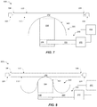
- FIG. 7 is a schematic representation of the FIG. 6 system 600 for a clickable touchpad 102 with a mechanical lockout system 200 engaged to lock touchpad 102 motion in accordance with disclosed embodiments. As shown in FIG. 7 latch 204 is engaged with catch 206 and movement of clicking element 300 and touchpad 102 is prevented.
- FIG. 8 is a schematic representation of another system 800 for a clickable touchpad 102 with a mechanical lockout system 200 in accordance with disclosed embodiments.
- system 800 may include a clicking element 300 that has been inverted and held with dome 302 in a snapped or deformed position and biasing member 304 compressed, or otherwise under tension against the deformation.
- controller 400 signals drive 202 to disengage latch 204 and catch 206 to allow biasing member 304 to move dome 302 and consequently touchpad 102 so that the user experiences a click, snap, or other haptic feedback.
- the system 800 may be reset with dome 302 back in a deformed position.
- the touchpad 102 may be fixed in place with the hinges 104 removed (indicated by the dashed lines).
- a haptic response e.g., a finger press
- the mechanical lockout system 200 may be triggered to cause clicking element 300 to snap and have the user experience the haptic feedback (i.e., the snap) even though the touchpad 102 does not appreciably move.
- other configurations are also possible.
- FIG. 9 is a schematic illustration of another system 900 for a clickable touchpad 102 in accordance with disclosed embodiments.
- biasing member 304 may include a pliable or otherwise resilient region 208 that deforms without allowing clicking element 300 to snap or deform up to a threshold force or deformation level.
- Embodiments of system 900 may also include a lockout controller 210 which may be a part of controller 400 , or a separate device, and includes appropriate circuitry, processors, software, firmware, or the like, to control any motion or haptic feedback for touchpad 102 as disclosed herein.
- resilient region 208 that include force sensors could be used to measure force applied to touchpad 102 irrespective of whether clicking element 300 is snapped or not.
- resilient region 208 may be a piezoelectric or similar material and lockout controller 210 may control snapping of clicking element 300 or other haptic feedback in accordance with sensed touches, gestures, or other trigger conditions as disclosed herein.
- FIG. 10 is a schematic illustration of another system 1000 for a clickable touchpad 102 in accordance with disclosed embodiments.
- a scissor mount 306 or other selectively movable device, is used to enable/disable motion of touchpad 202 as disclosed herein.
- lockout controller 210 which is illustrated as a component of an optional system controller 400 , may enable scissor mount 306 to move when certain touches, gestures, or the like are sensed and may lock to prevent touchpad 202 motion at other times.
- other configurations are also possible.
Abstract
Description
Claims (18)
Priority Applications (1)
| Application Number | Priority Date | Filing Date | Title |
|---|---|---|---|
| US16/241,600 US10719161B2 (en) | 2018-01-05 | 2019-01-07 | Dynamic suspension and passive haptic feedback for touch sensors |
Applications Claiming Priority (3)
| Application Number | Priority Date | Filing Date | Title |
|---|---|---|---|
| US201862614115P | 2018-01-05 | 2018-01-05 | |
| US201862713754P | 2018-08-02 | 2018-08-02 | |
| US16/241,600 US10719161B2 (en) | 2018-01-05 | 2019-01-07 | Dynamic suspension and passive haptic feedback for touch sensors |
Publications (2)
| Publication Number | Publication Date |
|---|---|
| US20190212861A1 US20190212861A1 (en) | 2019-07-11 |
| US10719161B2 true US10719161B2 (en) | 2020-07-21 |
Family
ID=67140665
Family Applications (1)
| Application Number | Title | Priority Date | Filing Date |
|---|---|---|---|
| US16/241,600 Active US10719161B2 (en) | 2018-01-05 | 2019-01-07 | Dynamic suspension and passive haptic feedback for touch sensors |
Country Status (2)
| Country | Link |
|---|---|
| US (1) | US10719161B2 (en) |
| CN (1) | CN110032275B (en) |
Families Citing this family (6)
| Publication number | Priority date | Publication date | Assignee | Title |
|---|---|---|---|---|
| US11245396B2 (en) * | 2018-05-11 | 2022-02-08 | Microsoft Technology Licensing, Llc | Limiting inadvertent actuations of a touchpad |
| TWI676923B (en) * | 2018-10-25 | 2019-11-11 | 群光電子股份有限公司 | Touchpad device |
| CN112540692B (en) * | 2019-09-20 | 2023-06-27 | 法雷奥汽车内部控制(深圳)有限公司 | Touch control operation device |
| US11209929B2 (en) | 2020-02-17 | 2021-12-28 | Robert Bosch Gmbh | Faulty pressure sensor determination of a portable communication device touch display |
| CN114415786A (en) * | 2022-01-27 | 2022-04-29 | 精元(重庆)电脑有限公司 | Global touch pad |
| US11625104B1 (en) * | 2022-02-22 | 2023-04-11 | Hewlett-Packard Development Company, L.P. | Click pads travel reductions |
Citations (3)
| Publication number | Priority date | Publication date | Assignee | Title |
|---|---|---|---|---|
| US20140002358A1 (en) * | 2010-12-23 | 2014-01-02 | Frederick Johannes Bruwer | Compact capacitive track pad |
| US20150009178A1 (en) * | 2012-01-13 | 2015-01-08 | Audi Ag | Input device comprising a touch-sensitive input surface |
| US20160124511A1 (en) * | 2014-10-30 | 2016-05-05 | Honda Motor Co., Ltd. | Vehicle operating device |
Family Cites Families (5)
| Publication number | Priority date | Publication date | Assignee | Title |
|---|---|---|---|---|
| KR20120028003A (en) * | 2010-09-14 | 2012-03-22 | 삼성전자주식회사 | Apparatus and method for 3-dimensional tactile display |
| US9478124B2 (en) * | 2013-10-21 | 2016-10-25 | I-Interactive Llc | Remote control with enhanced touch surface input |
| CN104035561B (en) * | 2014-06-11 | 2018-03-23 | 京东方科技集团股份有限公司 | Haptic feedback system, method and touch display unit |
| US10282000B2 (en) * | 2015-02-26 | 2019-05-07 | Dell Products L.P. | Touchpad with multiple tactile switches |
| CN107850923B (en) * | 2015-07-02 | 2021-03-12 | 瑟克公司 | Method and system for providing mechanical movement of a surface of a touch sensor |
-
2019
- 2019-01-07 CN CN201910013227.2A patent/CN110032275B/en active Active
- 2019-01-07 US US16/241,600 patent/US10719161B2/en active Active
Patent Citations (3)
| Publication number | Priority date | Publication date | Assignee | Title |
|---|---|---|---|---|
| US20140002358A1 (en) * | 2010-12-23 | 2014-01-02 | Frederick Johannes Bruwer | Compact capacitive track pad |
| US20150009178A1 (en) * | 2012-01-13 | 2015-01-08 | Audi Ag | Input device comprising a touch-sensitive input surface |
| US20160124511A1 (en) * | 2014-10-30 | 2016-05-05 | Honda Motor Co., Ltd. | Vehicle operating device |
Also Published As
| Publication number | Publication date |
|---|---|
| CN110032275A (en) | 2019-07-19 |
| US20190212861A1 (en) | 2019-07-11 |
| CN110032275B (en) | 2022-03-08 |
Similar Documents
| Publication | Publication Date | Title |
|---|---|---|
| US10719161B2 (en) | Dynamic suspension and passive haptic feedback for touch sensors | |
| US10242821B2 (en) | Localized key-click feedback | |
| US10928911B2 (en) | Movement capability for buttonless touchpads and forcepads | |
| JP5611282B2 (en) | Force imaging input devices and systems | |
| US20190079584A1 (en) | Input device with haptic interface | |
| EP2307947B1 (en) | Single sided capacitive force sensor for electronic devices | |
| US10627920B2 (en) | Integrated key plate for an input device | |
| KR20100023879A (en) | Touchpad assembly with tactile feedback | |
| US10353485B1 (en) | Multifunction input device with an embedded capacitive sensing layer | |
| WO2018112466A1 (en) | System for human-computer interfacing | |
| US20140035866A1 (en) | Hinged input device | |
| US20170249013A1 (en) | Touchpad system with multiple tracking methods: mechanical force positional sensor integrated with capacitive location tracking | |
| US11385718B2 (en) | Movement capability for buttonless touchpads and forcepads | |
| US11625104B1 (en) | Click pads travel reductions | |
| CN106095137B (en) | Top-mounted click plate module of double-water-plane basin body | |
| US20240061507A1 (en) | Non-Uniform Pressure Actuation Threshold Value |
Legal Events
| Date | Code | Title | Description |
|---|---|---|---|
| FEPP | Fee payment procedure |
Free format text: ENTITY STATUS SET TO UNDISCOUNTED (ORIGINAL EVENT CODE: BIG.); ENTITY STATUS OF PATENT OWNER: LARGE ENTITY |
|
| AS | Assignment |
Owner name: CIRQUE CORPORATION, UTAH Free format text: ASSIGNMENT OF ASSIGNORS INTEREST;ASSIGNORS:BYTHEWAY, JARED G.;MONSON, BRIAN;SIGNING DATES FROM 20180802 TO 20190108;REEL/FRAME:047930/0600 |
|
| AS | Assignment |
Owner name: CIRQUE CORPORATION, UTAH Free format text: ASSIGNMENT OF ASSIGNORS INTEREST;ASSIGNOR:WOOLLEY, RICHARD D.;REEL/FRAME:047940/0088 Effective date: 20180731 |
|
| STPP | Information on status: patent application and granting procedure in general |
Free format text: NON FINAL ACTION MAILED |
|
| STPP | Information on status: patent application and granting procedure in general |
Free format text: RESPONSE TO NON-FINAL OFFICE ACTION ENTERED AND FORWARDED TO EXAMINER |
|
| STPP | Information on status: patent application and granting procedure in general |
Free format text: FINAL REJECTION MAILED |
|
| STPP | Information on status: patent application and granting procedure in general |
Free format text: ADVISORY ACTION MAILED |
|
| STPP | Information on status: patent application and granting procedure in general |
Free format text: NOTICE OF ALLOWANCE MAILED -- APPLICATION RECEIVED IN OFFICE OF PUBLICATIONS |
|
| STCF | Information on status: patent grant |
Free format text: PATENTED CASE |
|
| MAFP | Maintenance fee payment |
Free format text: PAYMENT OF MAINTENANCE FEE, 4TH YEAR, LARGE ENTITY (ORIGINAL EVENT CODE: M1551); ENTITY STATUS OF PATENT OWNER: LARGE ENTITY Year of fee payment: 4 |