US10718423B2 - Wheel hub transmission - Google Patents
Wheel hub transmission Download PDFInfo
- Publication number
- US10718423B2 US10718423B2 US15/529,410 US201515529410A US10718423B2 US 10718423 B2 US10718423 B2 US 10718423B2 US 201515529410 A US201515529410 A US 201515529410A US 10718423 B2 US10718423 B2 US 10718423B2
- Authority
- US
- United States
- Prior art keywords
- cooling fins
- wheel hub
- cooling
- face
- hub transmission
- Prior art date
- Legal status (The legal status is an assumption and is not a legal conclusion. Google has not performed a legal analysis and makes no representation as to the accuracy of the status listed.)
- Expired - Fee Related, expires
Links
- 230000005540 biological transmission Effects 0.000 title claims abstract description 69
- 238000001816 cooling Methods 0.000 claims abstract description 133
- 230000002093 peripheral effect Effects 0.000 claims description 8
- 230000007423 decrease Effects 0.000 claims description 4
- 230000017525 heat dissipation Effects 0.000 description 16
- 239000003570 air Substances 0.000 description 15
- 230000000694 effects Effects 0.000 description 4
- 239000012080 ambient air Substances 0.000 description 3
- 238000010586 diagram Methods 0.000 description 2
- 238000005065 mining Methods 0.000 description 2
- 230000002349 favourable effect Effects 0.000 description 1
- 238000012986 modification Methods 0.000 description 1
- 230000004048 modification Effects 0.000 description 1
- 239000002245 particle Substances 0.000 description 1
- 238000004088 simulation Methods 0.000 description 1
Images


Classifications
-
- F—MECHANICAL ENGINEERING; LIGHTING; HEATING; WEAPONS; BLASTING
- F16—ENGINEERING ELEMENTS AND UNITS; GENERAL MEASURES FOR PRODUCING AND MAINTAINING EFFECTIVE FUNCTIONING OF MACHINES OR INSTALLATIONS; THERMAL INSULATION IN GENERAL
- F16H—GEARING
- F16H57/00—General details of gearing
- F16H57/04—Features relating to lubrication or cooling or heating
- F16H57/0412—Cooling or heating; Control of temperature
- F16H57/0415—Air cooling or ventilation; Heat exchangers; Thermal insulations
- F16H57/0416—Air cooling or ventilation
-
- B—PERFORMING OPERATIONS; TRANSPORTING
- B60—VEHICLES IN GENERAL
- B60B—VEHICLE WHEELS; CASTORS; AXLES FOR WHEELS OR CASTORS; INCREASING WHEEL ADHESION
- B60B35/00—Axle units; Parts thereof ; Arrangements for lubrication of axles
- B60B35/12—Torque-transmitting axles
-
- B—PERFORMING OPERATIONS; TRANSPORTING
- B60—VEHICLES IN GENERAL
- B60K—ARRANGEMENT OR MOUNTING OF PROPULSION UNITS OR OF TRANSMISSIONS IN VEHICLES; ARRANGEMENT OR MOUNTING OF PLURAL DIVERSE PRIME-MOVERS IN VEHICLES; AUXILIARY DRIVES FOR VEHICLES; INSTRUMENTATION OR DASHBOARDS FOR VEHICLES; ARRANGEMENTS IN CONNECTION WITH COOLING, AIR INTAKE, GAS EXHAUST OR FUEL SUPPLY OF PROPULSION UNITS IN VEHICLES
- B60K17/00—Arrangement or mounting of transmissions in vehicles
- B60K17/04—Arrangement or mounting of transmissions in vehicles characterised by arrangement, location or kind of gearing
- B60K17/043—Transmission unit disposed in on near the vehicle wheel, or between the differential gear unit and the wheel
Definitions
- the invention relates to a wheel hub transmission. Such transmissions are known and are sometimes also called mining truck transmissions.
- Wheel hub transmissions become very warm during operation. Due to the compact design, cooling elements can only be attached to a wheel hub transmission with difficulty. As a result, under load the wheel hub transmission either becomes too warm or the wheel hub transmission is only operated under a partial load.
- An object of the present invention is to specify a further embodiment of a wheel hub transmission, in particular, an embodiment of a wheel hub transmission which is characterized by an improved cooling effect.
- a wheel hub transmission including an outer surface that acts as an end face, which has radially oriented cooling fins at a regular distance from one another, and a cover which covers the cooling fins at the end face and which has a central opening, wherein the cover, along with pairs of adjacent cooling fins, defines a plurality of radially oriented cooling ducts.
- the advantage of the wheel hub transmission proposed here is that the cooling ducts resulting from the attachment of the cover lead to better heat dissipation from the wheel hub transmission compared with an end face only with cooling fins.
- an air flow is namely produced through the cooling ducts to the outside during rotating wheel hub transmission and the resultant centrifugal force. This favors heat dissipation.
- the end face is preferably in a plane which is perpendicular to a drive axle of the transmission, in particular, perpendicular to a drive axle of the transmission which in the assembled state of the transmission in a vehicle is transverse to the longitudinal axis of the vehicle.
- the end face is preferably on a side of the transmission facing outwards, i.e. facing away from the vehicle.
- the cover which covers the cooling fins at the end face is preferably in a plane which is parallel to the plane in which the end face is located.
- the cover preferably lies flat against the cooling fins and preferably is also firmly attached to the cooling fins.
- the cooling ducts preferably run in a star form, wherein they are oriented towards a common center.
- the common center preferably coincides with the central opening of the cover.
- Cooling air which subsequently flows through the radially oriented cooling ducts can flow in from outside through the central opening of the cover.
- An embodiment of the wheel hub transmission is characterized by a drive axle extended beyond the end face, wherein a radial fan with air flow towards the surrounding cooling ducts is attached to the extended drive axle.
- the radial fan is set in rotation by the drive axle.
- the radial fan therefore rotates at the rotational speed of the drive axle and thus at a significantly higher rotational speed than the wheel hub housing and its front surface.
- the rotating radial fan accelerates the respectively captured air particles and under the influence of centrifugal force these reach the cooling ducts connecting in a radial direction to the individual fan blades of the radial fan.
- the end face is preferably in a plane which runs vertically to that of the extended drive axle supporting the radial fans.
- a radial fan independent of the direction of rotation in other words a radial fan with fan blades not adjusted in an axial direction, is used.
- the independence of the direction of rotation of the radial fan ensures that the air-mass flow effective for heat dissipation occurs independently of the direction of rotation of the drive axle and thus independently of the direction of travel of a respective vehicle with such a wheel hub transmission.
- the cooling fins are of different lengths in a radial direction, resulting in at least long cooling fins and, in relation to the long cooling fins, short cooling fins.
- the radially oriented long and short cooling fins are distributed evenly along the periphery of the front surface.
- the sequence of longer and shorter cooling fins is such that a long cooling fin is followed by a number of short cooling fins, that is to say, for example, a short cooling fin, two short cooling fins, three short cooling fins and so on, and then a long cooling fin again in a regular sequence in a peripheral direction.
- the area effective for heat dissipation is increased by a high number of cooling fins.
- a particular embodiment of a wheel hub transmission with such an alternating sequence of long and short cooling fins provides that a long cooling fin is followed by a short cooling fin and then a long cooling fin again in a regular sequence in a peripheral direction. In each case, this leaves a sufficiently large inflowing opening for two adjacent cooling ducts separated from each other by a short cooling fin. On the other side, a very large surface effective for heat dissipation is also produced by the high number of long cooling fins.
- the cover has a conically stepped structure originating from the central opening.
- the height of the cover decreases with the conical gradation from inside to outside, the lowest height being produced in the region of the cooling fins.
- the height of the cover in the central section permits the attachment of a radial fan with sufficiently high fan blades in an axial direction.
- the height of the fan blades greatly influences the moved amount of air pressed into the cooling ducts and therefore the heat dissipation achievable as well.
- the lower height in the peripheral region that is to say, above the cooling fins, leads to a compact design, wherein the lower height results in an increase in the flow speed through the cooling ducts.
- the increased flow speed leads to effectively even heat dissipation, as would be produced with a flat cover and correspondingly higher cooling fins, in other words, an enlarged area of the cooling ducts.
- the compact design resulting from the conically stepped cover therefore does not have a negative effect on the heat dissipation achievable.
- Wheel hub transmissions in the manner described here and hereinafter come into question for use in vehicles.
- the invention is also a vehicle, for example, a heavy goods vehicle, in particular, a heavy goods vehicle in the form of a so-called mining truck, with at least one such wheel hub transmission, usually one wheel hub transmission respectively for each wheel.
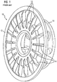
- FIG. 1 shows a known wheel hub transmission with a ribbed front surface
- FIG. 2 shows a wheel hub transmission in the manner proposed here
- FIG. 3 shows a section through the wheel hub transmission from FIG. 2 .
- FIG. 1 shows an isometric view of a section of the housing of a wheel hub transmission 10 .
- essentially an end face 12 of the housing of the wheel hub transmission 10 is shown.
- another component 16 is visible on the transmission end face.
- the interior of the wheel hub transmission 10 is not shown.
- FIG. 2 shows an embodiment of the wheel hub transmission 10 proposed here based on the section of the wheel hub transmission 10 shown in FIG. 1 .
- the proposed wheel hub transmission 10 and its housing have a cover 18 with a central opening on the end face 12 .
- the cover 18 and the cooling fins 14 define a multiplicity of cooling ducts 20 .
- an air flow is produced through the cooling ducts 20 due to the centrifugal force then effective.
- a drive shaft (not shown) of the wheel hub transmission 10 is routed to the exterior as far as the region of the cover 18 and there attached to a radial fan 22 , in particular, a radial fan independent of the direction of rotation 22 .
- the radial fan 22 is located above the central opening in the cover 18 in contact with the ambient air, draws in ambient air and forces this through the cooling ducts 20 .
- the resultant increased air-mass flow through the cooling ducts 20 leads to improved heat dissipation from the wheel hub transmission 10 .
- the drive shaft extended to drive the radial fan 22 may also be journaled in the extended section. Furthermore, or alternatively, an additional seal is optionally provided in the extended section.
- cooling fins 14 are the same length in a radial direction. This is reflected, for example, by means of the number of cooling fin ends visible on the outer edge of the cover 18 and the cooling fin ends visible through the central opening in the cover 18 .
- the long and short cooling fins 14 are arranged in an alternating sequence such that, in a peripheral direction, a long cooling fin 14 is followed by a short cooling fin 14 and then a long cooling fin 14 again (only the ends of the long cooling fins 14 are visible through the central opening in the cover 18 ). This alternating sequence results in a sufficiently large opening for incoming air being produced in a radial direction between each two long cooling fins 14 .
- long cooling fins 14 Although the constant use of long cooling fins 14 would enlarge the surface of the cooling ducts 20 , it would greatly restrict the air-mass flow actually entering the cooling ducts 20 due to the small opening width of the cooling ducts 20 on the inflowing side.
- An alternating sequence of long and short cooling fins 14 is a favorable compromise between the amount of air flowing into the cooling ducts 20 on the one hand and the inner surface of the cooling ducts 20 on the other hand.
- FIG. 3 shows a sectional view of the wheel hub transmission 10 according to FIG. 2 .
- a conically stepped structure of the cover 18 the fan blades of the radial fan 22 and the cooling fins 14 laterally delimiting the cooling ducts 20 are visible.
- the conically stepped structure of the cover 18 defines a central space sufficiently large to accommodate the radial fan 22 , the free height of which decreases in a radial direction, resulting in ambient air drawn in by the radial fan 22 being pressed through the cooling ducts 20 with increased speed.
- the increased speed and the resultant increased air-mass flow lead to good heat dissipation of the surface 12 at the end face of the wheel hub transmission 10 and thus of the overall wheel hub transmission 10 .
- a wheel hub transmission 10 comprising an outer surface that acts as an end face 12 , wherein the end face 12 has radially oriented cooling fins 14 at a regular distance from one another, wherein the wheel hub transmission 10 is characterized by a cover 18 which covers the cooling fins 14 at the end face and which has a central opening and wherein the cover 18 , along with pairs of adjacent cooling fins 14 , defines a multiplicity of radially oriented cooling ducts 20 through which intake air flows through the central opening during operation and effects a cooling or heat dissipation of the surface of the wheel hub transmission 10 and thus of the overall wheel hub transmission 10 .
Landscapes
- Engineering & Computer Science (AREA)
- Mechanical Engineering (AREA)
- General Engineering & Computer Science (AREA)
- Chemical & Material Sciences (AREA)
- Combustion & Propulsion (AREA)
- Transportation (AREA)
- General Details Of Gearings (AREA)
- Gears, Cams (AREA)
Abstract
Description
Claims (12)
Applications Claiming Priority (4)
| Application Number | Priority Date | Filing Date | Title |
|---|---|---|---|
| EP14194744.0A EP3026299A1 (en) | 2014-11-25 | 2014-11-25 | Wheel hub gear |
| EP14194744 | 2014-11-25 | ||
| EP14194744.0 | 2014-11-25 | ||
| PCT/EP2015/076923 WO2016083201A1 (en) | 2014-11-25 | 2015-11-18 | Wheel hub transmission |
Publications (2)
| Publication Number | Publication Date |
|---|---|
| US20180320777A1 US20180320777A1 (en) | 2018-11-08 |
| US10718423B2 true US10718423B2 (en) | 2020-07-21 |
Family
ID=52006845
Family Applications (1)
| Application Number | Title | Priority Date | Filing Date |
|---|---|---|---|
| US15/529,410 Expired - Fee Related US10718423B2 (en) | 2014-11-25 | 2015-11-18 | Wheel hub transmission |
Country Status (5)
| Country | Link |
|---|---|
| US (1) | US10718423B2 (en) |
| EP (2) | EP3026299A1 (en) |
| CN (1) | CN107002859B (en) |
| ES (1) | ES2702975T3 (en) |
| WO (1) | WO2016083201A1 (en) |
Families Citing this family (6)
| Publication number | Priority date | Publication date | Assignee | Title |
|---|---|---|---|---|
| US10648554B2 (en) | 2014-09-02 | 2020-05-12 | Polaris Industries Inc. | Continuously variable transmission |
| CN106246890A (en) * | 2016-10-18 | 2016-12-21 | 安徽省六安市朝晖机械制造有限公司 | A kind of planetary gears from heat radiation |
| CN111836980A (en) | 2018-03-19 | 2020-10-27 | 北极星工业有限公司 | CVT |
| US10655574B2 (en) * | 2018-09-14 | 2020-05-19 | Kawasaki Jukogyo Kabushiki Kaisha | Side-by-side vehicle |
| WO2022165160A1 (en) | 2021-01-29 | 2022-08-04 | Polaris Industries Inc. | Electronically-controlled continuously variable transmission for a utility vehicle |
| CN117429203B (en) * | 2023-12-18 | 2024-03-08 | 福建金尚机械有限公司 | Forging automobile hub with protection device |
Citations (12)
| Publication number | Priority date | Publication date | Assignee | Title |
|---|---|---|---|---|
| US6793057B1 (en) * | 2002-12-31 | 2004-09-21 | Robert P. Smith, Jr. | Rotary friction system |
| EP1832461A1 (en) | 2006-03-07 | 2007-09-12 | Nissan Motor Company Limited | Vehicle Drive |
| US20080308364A1 (en) | 2007-06-13 | 2008-12-18 | Webb Wheel Products, Inc. | Lightweight brake drum with middle position squealer band |
| US20090032321A1 (en) | 2006-08-31 | 2009-02-05 | American Axle & Manufacturing, Inc. | Electric wheel motor assembly |
| EP2168860A1 (en) | 2008-09-30 | 2010-03-31 | Honda Motor Co., Ltd. | Electric motorcycle |
| CN201599351U (en) | 2009-12-15 | 2010-10-06 | 蔡长平 | Brake drum |
| CN102165211A (en) * | 2008-09-25 | 2011-08-24 | 雷诺股份公司 | Brake drum and drum hub, particularly for a motor vehicle, with improved heat exchange, and vehicle so equipped |
| US20110290882A1 (en) | 2010-05-28 | 2011-12-01 | Microsoft Corporation | Qr code detection |
| US8251674B1 (en) * | 2011-05-04 | 2012-08-28 | John Pairaktaridis | Brushless cooling fan |
| CN103573717A (en) | 2012-07-24 | 2014-02-12 | 德昌电机(深圳)有限公司 | Fan and impeller thereof |
| CN203562919U (en) | 2013-09-29 | 2014-04-23 | 泰荣动力科技股份有限公司 | Hub motor and heat dissipation structure |
| CN104139827A (en) | 2013-05-06 | 2014-11-12 | 罗伯特·博世有限公司 | Wheel hub driving device and cooling element used for the wheel hub driving device |
Family Cites Families (1)
| Publication number | Priority date | Publication date | Assignee | Title |
|---|---|---|---|---|
| JP5534934B2 (en) * | 2010-05-20 | 2014-07-02 | アイシン精機株式会社 | In-wheel motor cooling structure |
-
2014
- 2014-11-25 EP EP14194744.0A patent/EP3026299A1/en not_active Withdrawn
-
2015
- 2015-11-18 EP EP15798016.0A patent/EP3191740B1/en not_active Not-in-force
- 2015-11-18 WO PCT/EP2015/076923 patent/WO2016083201A1/en not_active Ceased
- 2015-11-18 CN CN201580063760.XA patent/CN107002859B/en not_active Expired - Fee Related
- 2015-11-18 ES ES15798016T patent/ES2702975T3/en active Active
- 2015-11-18 US US15/529,410 patent/US10718423B2/en not_active Expired - Fee Related
Patent Citations (14)
| Publication number | Priority date | Publication date | Assignee | Title |
|---|---|---|---|---|
| US6793057B1 (en) * | 2002-12-31 | 2004-09-21 | Robert P. Smith, Jr. | Rotary friction system |
| EP1832461A1 (en) | 2006-03-07 | 2007-09-12 | Nissan Motor Company Limited | Vehicle Drive |
| US20090032321A1 (en) | 2006-08-31 | 2009-02-05 | American Axle & Manufacturing, Inc. | Electric wheel motor assembly |
| US20080308364A1 (en) | 2007-06-13 | 2008-12-18 | Webb Wheel Products, Inc. | Lightweight brake drum with middle position squealer band |
| CN101755144A (en) | 2007-06-13 | 2010-06-23 | Webb车轮产品公司 | Lightweight brake drum with middle position squealer band |
| CN102165211A (en) * | 2008-09-25 | 2011-08-24 | 雷诺股份公司 | Brake drum and drum hub, particularly for a motor vehicle, with improved heat exchange, and vehicle so equipped |
| EP2168860A1 (en) | 2008-09-30 | 2010-03-31 | Honda Motor Co., Ltd. | Electric motorcycle |
| CN201599351U (en) | 2009-12-15 | 2010-10-06 | 蔡长平 | Brake drum |
| US20110290882A1 (en) | 2010-05-28 | 2011-12-01 | Microsoft Corporation | Qr code detection |
| US8251674B1 (en) * | 2011-05-04 | 2012-08-28 | John Pairaktaridis | Brushless cooling fan |
| CN103573717A (en) | 2012-07-24 | 2014-02-12 | 德昌电机(深圳)有限公司 | Fan and impeller thereof |
| US20140064973A1 (en) | 2012-07-24 | 2014-03-06 | Johnson Electric S.A. | Impeller and method for driving fluids using the same |
| CN104139827A (en) | 2013-05-06 | 2014-11-12 | 罗伯特·博世有限公司 | Wheel hub driving device and cooling element used for the wheel hub driving device |
| CN203562919U (en) | 2013-09-29 | 2014-04-23 | 泰荣动力科技股份有限公司 | Hub motor and heat dissipation structure |
Also Published As
| Publication number | Publication date |
|---|---|
| ES2702975T3 (en) | 2019-03-06 |
| EP3191740A1 (en) | 2017-07-19 |
| US20180320777A1 (en) | 2018-11-08 |
| EP3026299A1 (en) | 2016-06-01 |
| WO2016083201A1 (en) | 2016-06-02 |
| EP3191740B1 (en) | 2018-09-26 |
| CN107002859B (en) | 2019-10-15 |
| CN107002859A (en) | 2017-08-01 |
Similar Documents
| Publication | Publication Date | Title |
|---|---|---|
| US10718423B2 (en) | Wheel hub transmission | |
| EP3106667B1 (en) | Centrifugal fan with dual outlets in the same direction and fan frame thereof | |
| US20160312877A1 (en) | Gearset with an air-guiding cover | |
| US10563664B2 (en) | Fan impeller and radiator fan module | |
| US10544790B2 (en) | Ceiling fan including a heat-dissipating device | |
| CN108349375A (en) | Cooling device | |
| KR101342746B1 (en) | Cooling fan | |
| US20140356149A1 (en) | Fan | |
| US20130094954A1 (en) | Blower device | |
| EP3245715B1 (en) | Electric motor having improved cooling | |
| CN107112858A (en) | Electric machines with deflectors | |
| US12146502B2 (en) | Impeller and fan employing same | |
| US9822800B2 (en) | Fan for a motor vehicle comprising a stator | |
| US20150354585A1 (en) | Slim fan structure | |
| US9841035B2 (en) | Heat dissipation fan | |
| JP5747888B2 (en) | Blower | |
| DE202015101733U1 (en) | Electric motor with improved cooling | |
| JP2017061919A (en) | Centrifugal Pump | |
| CN104343855A (en) | Cover device for brake disc | |
| US11339801B2 (en) | Centrifugal blower having an integrated cooling function | |
| CN110023651B (en) | Gearbox with a housing having a lower housing part on which an upper housing part is mounted | |
| US10385873B2 (en) | Fan | |
| KR101994113B1 (en) | Vented Brake Disc | |
| CN204794502U (en) | Front end housing is equipped with ventilated motor of louvre | |
| CN105317705B (en) | Fan structure |
Legal Events
| Date | Code | Title | Description |
|---|---|---|---|
| AS | Assignment |
Owner name: SIEMENS AKTIENGESELLSCHAFT, GERMANY Free format text: ASSIGNMENT OF ASSIGNORS INTEREST;ASSIGNORS:BECKA, SIMON;KESCHTGES, FRANK;SIGNING DATES FROM 20170405 TO 20170410;REEL/FRAME:042496/0192 |
|
| AS | Assignment |
Owner name: FLENDER GMBH, GERMANY Free format text: ASSIGNMENT OF ASSIGNORS INTEREST;ASSIGNOR:SIEMENS AKTIENGESELLSCHAFT;REEL/FRAME:044333/0019 Effective date: 20171012 |
|
| STPP | Information on status: patent application and granting procedure in general |
Free format text: DOCKETED NEW CASE - READY FOR EXAMINATION |
|
| STPP | Information on status: patent application and granting procedure in general |
Free format text: NON FINAL ACTION MAILED |
|
| STPP | Information on status: patent application and granting procedure in general |
Free format text: RESPONSE TO NON-FINAL OFFICE ACTION ENTERED AND FORWARDED TO EXAMINER |
|
| STPP | Information on status: patent application and granting procedure in general |
Free format text: FINAL REJECTION MAILED |
|
| STPP | Information on status: patent application and granting procedure in general |
Free format text: ADVISORY ACTION MAILED |
|
| STPP | Information on status: patent application and granting procedure in general |
Free format text: DOCKETED NEW CASE - READY FOR EXAMINATION |
|
| STPP | Information on status: patent application and granting procedure in general |
Free format text: NOTICE OF ALLOWANCE MAILED -- APPLICATION RECEIVED IN OFFICE OF PUBLICATIONS |
|
| STCF | Information on status: patent grant |
Free format text: PATENTED CASE |
|
| FEPP | Fee payment procedure |
Free format text: MAINTENANCE FEE REMINDER MAILED (ORIGINAL EVENT CODE: REM.); ENTITY STATUS OF PATENT OWNER: LARGE ENTITY |
|
| LAPS | Lapse for failure to pay maintenance fees |
Free format text: PATENT EXPIRED FOR FAILURE TO PAY MAINTENANCE FEES (ORIGINAL EVENT CODE: EXP.); ENTITY STATUS OF PATENT OWNER: LARGE ENTITY |
|
| STCH | Information on status: patent discontinuation |
Free format text: PATENT EXPIRED DUE TO NONPAYMENT OF MAINTENANCE FEES UNDER 37 CFR 1.362 |
|
| FP | Lapsed due to failure to pay maintenance fee |
Effective date: 20240721 |