US10716241B2 - Air flow distribution system for data center server racks - Google Patents
Air flow distribution system for data center server racks Download PDFInfo
- Publication number
- US10716241B2 US10716241B2 US14/473,395 US201414473395A US10716241B2 US 10716241 B2 US10716241 B2 US 10716241B2 US 201414473395 A US201414473395 A US 201414473395A US 10716241 B2 US10716241 B2 US 10716241B2
- Authority
- US
- United States
- Prior art keywords
- air
- air foil
- foil
- cable
- aisle
- Prior art date
- Legal status (The legal status is an assumption and is not a legal conclusion. Google has not performed a legal analysis and makes no representation as to the accuracy of the status listed.)
- Active, expires
Links
- 239000011888 foil Substances 0.000 claims abstract description 215
- 238000000034 method Methods 0.000 claims abstract description 27
- 238000001816 cooling Methods 0.000 claims abstract description 14
- 230000000712 assembly Effects 0.000 description 16
- 238000000429 assembly Methods 0.000 description 16
- 230000009977 dual effect Effects 0.000 description 5
- 230000015572 biosynthetic process Effects 0.000 description 2
- 239000002184 metal Substances 0.000 description 2
- 230000007423 decrease Effects 0.000 description 1
- 230000005611 electricity Effects 0.000 description 1
- 238000005286 illumination Methods 0.000 description 1
- 238000012986 modification Methods 0.000 description 1
- 230000004048 modification Effects 0.000 description 1
- 230000003014 reinforcing effect Effects 0.000 description 1
Images


Classifications
-
- H—ELECTRICITY
- H05—ELECTRIC TECHNIQUES NOT OTHERWISE PROVIDED FOR
- H05K—PRINTED CIRCUITS; CASINGS OR CONSTRUCTIONAL DETAILS OF ELECTRIC APPARATUS; MANUFACTURE OF ASSEMBLAGES OF ELECTRICAL COMPONENTS
- H05K7/00—Constructional details common to different types of electric apparatus
- H05K7/20—Modifications to facilitate cooling, ventilating, or heating
- H05K7/20709—Modifications to facilitate cooling, ventilating, or heating for server racks or cabinets; for data centers, e.g. 19-inch computer racks
- H05K7/20718—Forced ventilation of a gaseous coolant
- H05K7/20745—Forced ventilation of a gaseous coolant within rooms for removing heat from cabinets, e.g. by air conditioning device
-
- F—MECHANICAL ENGINEERING; LIGHTING; HEATING; WEAPONS; BLASTING
- F21—LIGHTING
- F21V—FUNCTIONAL FEATURES OR DETAILS OF LIGHTING DEVICES OR SYSTEMS THEREOF; STRUCTURAL COMBINATIONS OF LIGHTING DEVICES WITH OTHER ARTICLES, NOT OTHERWISE PROVIDED FOR
- F21V33/00—Structural combinations of lighting devices with other articles, not otherwise provided for
- F21V33/0088—Ventilating systems
- F21V33/0092—Ventilating systems with heating or cooling devices
-
- F—MECHANICAL ENGINEERING; LIGHTING; HEATING; WEAPONS; BLASTING
- F21—LIGHTING
- F21W—INDEXING SCHEME ASSOCIATED WITH SUBCLASSES F21K, F21L, F21S and F21V, RELATING TO USES OR APPLICATIONS OF LIGHTING DEVICES OR SYSTEMS
- F21W2131/00—Use or application of lighting devices or systems not provided for in codes F21W2102/00-F21W2121/00
- F21W2131/40—Lighting for industrial, commercial, recreational or military use
Definitions
- the embodiments of the present disclosure are directed to an air flow distribution system for cooling server racks that reduce the power consumption required for cooling of server racks.
- an air flow distribution system for cooling server racks includes at least one server rack partially defining a hot aisle and a cold aisle, a first air foil disposed above the at least one server rack, and a second air foil disposed above the first air foil.
- the first air foil and the second air foil are configured to receive air from the hot aisle, and to form turbulent wake patterns in the cold aisle partially defined by the at least one server rack.
- the air flow distribution system may further include a ceiling member disposed above the second air foil. The first air foil, the second air foil, and the ceiling member may be configured to receive air from the hot aisle and to form turbulent wake patterns in the cold aisle partially defined by the at least one server rack.
- the air flow distribution system may further include at least one air circulation member that is configured to direct air between the first air foil and the second air foil or between the ceiling member and the first air foil and between the first air foil and the second air foil.
- the one or more air circulation members may include at least one fan.
- At least a portion of the ceiling member may include a convex surface that interfaces with the air flowing from the hot aisle to the cold aisle.
- the ceiling member is disposed at least partially downstream of the second air foil.
- the first air foil may include a surface that is convex with respect to the air flow
- the second air foil may include a first surface that is concave with respect to the air flow and a second surface that is convex with respect to the air flow.
- the first air foil may be configured and movably coupled to cover an electrical enclosure receptacle configured to receive at least one cable or a support member for the at least one cable for the at least one server rack.
- the first air foil may be configured to rotatably move to enable access to the at least one cable or a support member for the at least one cable.
- the cable may include an electrical cable, a fiber-optic cable, or a combination of an electrical cable and a fiber-optic cable.
- the present disclosure relates to a method for distributing air flow for cooling server racks.
- the method includes disposing at least one server rack at least partially defining a hot aisle and a cold aisle, and causing air to be directed between a first air foil disposed above the at least one server rack and a second air foil disposed above the first air foil.
- the air exiting from the first air foil and the second air foil form turbulent wake patterns in the cold aisle at least partially defined by the at least one server rack.
- causing the air to be directed between the first air foil and the second air foil includes causing the air to be directed between a ceiling member disposed above the second air foil and the second air foil, and between the first air foil and the second air foil.
- the air exiting from the ceiling member, the first air foil, and the second air foil form turbulent wake patterns in the cold aisle partially defined by the at least one server rack.
- the ceiling member may be configured as a convex surface that interfaces with the air flowing from the hot aisle to the cold aisle, and the method may include causing the air to be directed between the ceiling member configured as a convex surface and the second air foil and between the second air foil and the first air foil, wherein the air exiting from the at least one ceiling member configured as a convex surface, the second air foil, and the first air foil form turbulent wake patterns in the cold aisle partially defined by the at least one server rack.
- the first air foil is configured and movably coupled to cover an electrical enclosure receptacle configured to receive at least one cable or a support member for the at least one cable
- the method may include causing the air to be directed between the first air foil that is configured and movably coupled to cover the electrical enclosure receptacle and the second air foil.
- the first air foil is further configured to rotatably move to enable access to the at least one cable or a support member for the at least one cable
- the method may include causing the air to be directed between the first air foil that is configured to rotatably move to enable access to the at least one cable or a support member for the at least one cable and the second air foil.
- the cable received by the electrical enclosure receptacle may include an electrical cable, a fiber-optic cable, or a combination of an electrical cable and a fiber-optic cable
- the method may include causing the air to be directed between the first air foil that is configured and movably coupled to cover the electrical enclosure receptacle receiving the cable and the second air foil.
- the present disclosure relates to an electrical enclosure assembly for at least one server rack at least partially defining a hot aisle and a cold aisle, that includes an electrical enclosure receptacle configured to receive at least one cable or a support member of the at least one cable, and a cover member movably coupled to cover the electrical enclosure receptacle, the cover member configured as an air foil for air flowing between the hot aisle and the cold aisle.
- the cover member configured as an air foil is a first air foil
- the electrical enclosure assembly may further include a second air foil, wherein the first air foil and the second air foil are configured to form in the cold aisle turbulent wake patterns in the air flowing into the cold aisle.
- An air circulation member may direct the air flowing between the first air foil and the second air foil.
- the cover member may be configured to rotatably move to enable access to the at least one cable or a support member of the at least one cable.
- the electrical enclosure assembly may further include a lighting enclosure assembly configured to receive at least one lighting member configured and disposed to project light, wherein at least a portion of the lighting enclosure assembly forms an extension of the air foil.
- the electrical enclosure assembly may further include at least one lighting member disposed in the lighting enclosure assembly.
- FIG. 1 is a plan view of a portion of a data center subassembly that includes adjacent server racks forming a first side of a central hot aisle and adjacent server racks forming a second side of the central hot aisle;
- FIG. 2 is an elevation view of a portion of the data center subassembly illustrating sets of three fans above sets of adjacent server racks in which the sets of adjacent server racks are disposed between respective vertical columns;
- FIG. 3 is a partial view of the elevation view of FIG. 2 of a portion of the data center subassembly illustrating sets of three fans that are positioned above sets of adjacent server racks that are disposed between vertical columns, and partially projecting over upper air foils that are positioned above sets of adjacent server racks according to one exemplary embodiment of the present disclosure;
- FIG. 4 is an end elevation view of the portion of the data center subassembly of FIGS. 1, 2, and 3 showing a central hot aisle having a common fan enclosure above the hot aisle;
- FIG. 5 is a perspective view looking at the portion of the data center subassembly of FIGS. 1-4 from below;
- FIG. 6A is a perspective view of the portion of the data center subassembly illustrating a cold aisle opposite the central hot aisle and light boxes that include covers that also serve as lower air foils with respect to upper air foils;
- FIG. 6B is an end elevation view of FIG. 6A and illustrates a contoured concave ceiling of the central cold aisle to form turbulent wake patterns in the central cold aisle for more efficient cooling of the sets of server racks according to exemplary embodiments of the present disclosure
- FIG. 7A is a perspective view of the portion of the data center subassembly of FIGS. 6A and 6B showing the air foils, which also serve as light box covers, hinged up at an angle to allow access to the cable trays;
- FIG. 7B is an end elevation view of the portion of the data center subassembly of FIG. 7A showing the air foils, which also serve as light box covers, hinged up at an angle to allow access to the cable trays;
- FIG. 8 is a perspective view of the cold aisle of FIGS. 6A, 6B, 7A, 7B with the person positioned to illustrate an exemplary height of the sets of server racks and the elevation of the air foils above the light boxes;
- FIG. 9 is an end elevation view of the portion of the data center subassembly of FIGS. 6A-8 illustrating the hot aisle opposite the central cold aisle and light boxes that include covers that also serve as lower air foils with respect to upper air foils and a contoured concave ceiling of the central cold aisle to form turbulent wake patterns in the central cold aisle for more efficient cooling of the sets of server racks according to exemplary embodiments of the present disclosure;
- FIG. 10A includes an exploded perspective view of the electrical light and cable tray box and the dual purpose cover and lower air foil according to one exemplary embodiment of the present disclosure
- FIG. 10B includes an elevation view proximal to a user of the electrical light and cable tray boxes and the covers, which also server as lower air foils according to FIG. 10A ;
- FIG. 10C includes another elevation view of the electrical light and cable tray boxes and the dual purpose covers and lower air foils according to FIG. 10A ;
- FIG. 10D includes another view of the electrical light and cable tray boxes and the dual purpose covers and lower air foils according to FIG. 10A ;
- FIG. 10E is a detailed view of an extendable strut member illustrated in FIG. 10E ;
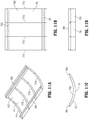
- FIG. 11A includes a perspective view of the contoured or concave ceiling that is positioned above the cold aisle in FIGS. 6A-7B and 9 above;
- FIG. 11B includes an elevation view of the contoured or concave ceiling of FIG. 11A that is positioned above the cold aisle;
- FIG. 11C includes another elevation view of the contoured or concave ceiling of FIG. 11A that is positioned above the cold aisle;
- FIG. 11D includes another view of the contoured or concave ceiling of FIG. 11A that is positioned above the cold aisle;
- FIG. 12 illustrates an alternative embodiment of the portion of the data center subassembly 10 illustrated in FIG. 8 that includes as a ceiling a wave-like sheet-metal canopy above the hot aisle and crossing above the sets of three fans FIGS. 1-5 , and crossing above the cold aisle.
- the present disclosure relates to an air flow distribution system for server racks that significantly reduces the power requirements for cooling server racks within data centers.
- FIG. 1 is a plan view of a portion of a data center subassembly 10 that includes adjacent server racks 21 a , 21 b , . . . , 21 n forming a first side of a central hot aisle 25 and adjacent server racks 22 a , 22 b , . . . , 22 n forming a second side of the central hot aisle 25 .
- a set of active air circulation members or forced air circulation members e.g., three fans 31 a
- a set of active air circulation members or forced air circulation members e.g., three fans 32 a
- Other sets of active circulation members or forced circulation members are also correspondingly disposed with the other server racks 21 b , . . . , 21 n and 22 b , . . . , 22 n .
- the fans 31 a , 32 a are positioned to circulate air in the upward vertical direction to remove heat from the central hot aisle 25 .
- FIGS. 2 and 3 are elevation views of the portion of the data center subassembly 10 mounted on floor 165 and illustrating sets of active circulation members or forced circulation members, e.g., sets of three fans 32 a , 32 b , 32 c , 32 d , 32 e , 32 f , above sets of adjacent server racks 22 a , 22 b , 22 c , 22 d , 22 e , 22 f , respectively.
- Sets of adjacent server racks 22 a , 22 b , 22 c , 22 d , 22 e , 22 f are disposed between respective vertical columns 421 , 422 , 423 , 424 , 425 , 426 , 427 .
- the sets of three fans 32 a , 32 b , 32 c , 32 d partially project over upper air foil 34 a , 34 b , 34 c , 34 d that are positioned above sets of adjacent server racks 22 a , 22 b , 22 c , 22 d , respectively.
- FIG. 4 is an end elevation view of the portion of the data center subassembly 10 showing the central hot aisle 25 having a common fan enclosure 51 above the hot aisle 25 .
- Opposing vertical columns 411 and 421 are disposed on opposite sides of the hot aisle 25 .
- the sets of server racks 21 a , . . . , 21 e and 22 a , . . . , 22 e at least partially define the hot aisle 25 .
- FIG. 5 is a perspective view looking at the portion of the data center subassembly 10 of FIGS. 1-4 from below illustrating the data center subassembly 10 mounted on floor 165 .
- FIGS. 6A and 6B illustrate the portion of the data center subassembly 10 (with column 422 omitted) and a cold aisle 45 opposite central hot aisle 25 with a person 5 standing in the cold aisle to illustrate one embodiment of the height of the sets of server racks 22 a , 22 b .
- the sets of server racks 22 a , 22 b . . . at least partially define the hot aisle 25 and the cold aisle 45 .
- Electrical enclosure assemblies 50 a and 50 b include electrical enclosure receptacles or light and cable tray boxes 52 a , 52 b , and are disposed immediately above adjacent sets of server racks 22 a , 22 b , respectively.
- the light and cable tray boxes 52 a , 52 b include cable support members, e.g., upper cable tray 621 and lower cable tray 622 .
- the upper cable tray 621 and lower cable tray 622 support cables that may carry electricity and/or data to and/or from the sets of server racks 22 a , 22 b . . . .
- the cables may include electrically conductive cables, fiber-optic cables, or other types of cables for conveying power, control signals, data, and the like.
- the electrical enclosure assemblies 50 a , 50 b include electrical enclosure receptacles or light and cable tray boxes 52 a , 52 b and covers 54 a , 54 b , respectively, for the electrical enclosure receptacles or light and cable tray boxes 52 a , 52 b that also serve as first or lower air foils with respect to second or upper air foils 34 a , 34 b . That is, upper air foils 34 a and 34 b are positioned at a suitable distance D 1 above lower air foils 54 a and 54 b , respectively.
- the first or lower air foils or covers 54 a , 54 b are configured and movably coupled to cover the electrical enclosure receptacles 52 a , 52 b (see FIGS. 10A-10E ) that are configured to receive cables 6211 , 6222 (see FIG. 8 ) or a support member, e.g., cable trays 621 , 622 , respectively (see FIG. 8 ), for the cables 6211 , 6222 for the sets of one or more server racks 22 a or 22 b .
- the cables 6211 , 6222 may include an electrical cable, a fiber-optic cable, or a combination of an electrical cable and a fiber-optic cable.
- the sets of three fans 32 a , 32 b are positioned to exhaust cold air from the common fan enclosure 51 at an angle ⁇ 1 with respect to the vertical of approximately 45 degrees towards a ceiling member 65 above the adjacent sets of server racks 22 a , 22 b.
- the cold aisle 45 includes a contoured or convex ceiling member 75 extending at least partially along the cold aisle 45 .
- the contoured or convex ceiling member 75 is disposed a distance D 2 from the upper air foils 34 a , 34 b such that a portion of the cold air flowing from the sets of three fans 32 a , 32 b is deflected downwardly into the cold aisle 45 by the contoured or convex ceiling member 75 and the upper air foils 34 a , 34 b , as indicated by the arrows A.
- the distance D 2 defines the dimension of an effective nozzle throat defined by the upper air foils 34 a , 34 b and the contoured or convex ceiling member 75 .
- the ceiling member 75 thus includes a convex surface 751 that interfaces with the air indicated by arrows A flowing from the hot aisle 25 to the cold aisle 45 .
- the ceiling member 75 is disposed at least partially downstream of the upper air foils 34 a , 34 b.
- Another portion of the cold air flowing from the sets of three fans 32 a , 32 b is deflected downwardly into the cold aisle 45 by the upper air foils 34 a , 34 b and the lower air foils 54 a , 54 b through the area defined by the distance D 1 .
- the first or lower air foils 54 a , 54 b include surfaces 541 a , 541 b that are convex with respect to the air flow indicated by the arrows A.
- the second or upper air foils 34 a , 34 b include first surfaces 341 a , 341 b that are concave with respect to the air flow indicated by the arrows A and concave with respect to the surfaces 541 a , 541 b of the lower air foils 54 a , 54 b that are convex with respect to the air flow indicated by the arrows A.
- the second or upper air foils 34 a , 34 b include second surfaces 342 a , 342 b that are convex with respect to the air flow indicated by the arrows A.
- the electrical enclosure assemblies 50 a , 50 b each may further include lighting enclosure assemblies 521 a , 521 b that are configured to receive at least one lighting member 522 a , 522 b , respectively, that is configured and disposed to project light L, wherein at least a portion of the lighting enclosure assemblies 521 a , 521 b forms an extension 54 a ′, 54 b ′ of the first air foils or covers 54 a , 54 b .
- the lighting enclosure assemblies 521 a , 521 b may each further include at least one lighting member 522 a , 522 b disposed in the lighting enclosure assemblies 521 a , 521 b , respectively.
- the light L may project vertically downward toward the floor 165 supporting the sets of one or more server racks 22 a , 22 b .
- the electrical enclosure assemblies 50 a , 50 b may further include the second or upper air foils 34 a , 34 b (in conjunction with support of the second or upper air foils 34 a , 34 b by at least one of the vertical columns, e.g., column 421 or column 423 or both). Due to the forced flow of the air from the contoured or convex ceiling member 75 , the upper air foils 34 a , 34 b and the lower air foils 54 a , 54 b , both portions of the air flowing therefrom are formed into turbulent wake patterns 100 in the cold aisle 45 .
- the formation of the turbulent wake patterns 100 results in enhanced, more efficient cooling of the sets of server racks 22 a , 22 b .
- Increases or decreases in the strength or occurrence of the turbulent wake patterns 100 may be controlled by varying the operating speed of at least one fan in the sets of three fans 32 a , 32 b . Consequently, the first or lower air foils, which also serve as covers, 54 a , 54 b , the second or upper air foils 34 a , 34 b , and the contoured or convex ceiling members 75 are aerodynamically designed to create the turbulent wake patterns 100 .
- an air flow distribution system 80 for cooling of the sets of server racks is defined by at least one server rack, e.g., server racks 22 a , 22 b , at least partially defining hot aisle 25 and cold aisle 45 , a first air foil, e.g., lower air foils 54 a , 54 b , disposed above the one or more server racks 22 a , 22 b , and a second air foil, e.g., upper air foils 34 a , 34 b , disposed above the first air foil, e.g., lower air foils 54 a , 54 b , wherein the first air foil 54 a and/or 54 b and the second air foil 34 a and/or 34 b are configured to receive the air indicated by arrows A from the hot aisle 25 , and to form turbulent wake patterns 100 in the cold aisle 45 partially defined by the one or more sets of server racks, e
- the air flow distribution system 80 may further include at least one active circulation member or forced circulation member, e.g., the sets of three fans 32 a , 32 b , the ceiling member 65 , the contoured or convex ceiling member 75 , at least one of the second or upper air foils 34 a , 34 b , and at least one of the first or lower air foils 54 a , 54 b , such that the configurations and geometrical relationships between these components cause the formation of the turbulent wake patterns 100 in the cold aisle 45 as described herein.
- active circulation member or forced circulation member e.g., the sets of three fans 32 a , 32 b , the ceiling member 65 , the contoured or convex ceiling member 75 , at least one of the second or upper air foils 34 a , 34 b , and at least one of the first or lower air foils 54 a , 54 b , such that the configurations and geometrical relationships between these components cause the formation of the turbulent wake patterns 100 in the cold aisle 45 as described
- the cold aisle 45 includes a planar or flat surface such as ceiling member 65 ′ extending at least partially along the cold aisle 45 , as illustrated by the dashed line in FIG. 6B , as opposed to the contoured or convex ceiling member 75 .
- the planar or flat surface ceiling member 65 ′ is disposed a distance D 2 ′ from the upper air foils 34 a , 34 b such that a portion of the cold air flowing from the sets of active circulation members, e.g., three fans 32 a , 32 b , is deflected downwardly into the cold aisle 45 by the planar or flat surface ceiling 65 ′ and the upper air foils 34 a , 34 b .
- the distance D 2 ′ defines the diameter of an effective nozzle throat defined by the upper air foils 34 a , 34 b and the planar or flat surface ceiling 65 ′.
- FIGS. 7A and 7B illustrate the portion of the data center subassembly 10 of FIGS. 6A and 6B showing the electrical equipment enclosures or light and cable tray boxes 52 a , 52 b and the air foils 54 a , 54 b , which also serve as light box covers, hinged up at an angle ⁇ of about 35 degrees (with respect to the initial position of the air foils 54 a , 54 b as illustrated in FIG. 6B ) to allow access to the cable trays 621 , 622 .
- the first air foils 54 a , 54 b are configured to rotatably move to enable access to the one or more cables 6211 , 6222 or the support members, e.g., cable trays 621 , 622 , of the one or more cables 6211 , 6222 , respectively.
- FIG. 8 is a perspective view of the cold aisle 45 of FIGS. 6A-7B with the person 5 positioned to illustrate an exemplary height of the sets of server racks 22 a , 22 b.
- FIG. 8 also illustrates that the first or lower air foils or covers 54 a , 54 b are configured and movably coupled to cover an electrical enclosure receptacle 52 a or 52 b (see FIGS. 10A-10E ) that is configured to receive cables 6211 , 6222 or a support member, e.g., cable trays 621 , 622 , respectively, of the cables 6211 , 6222 for the sets of one or more server racks 22 a , 22 b .
- the cables 6211 , 6222 may include an electrical cable, a fiber-optic cable, or a combination of an electrical cable and a fiber-optic cable.
- FIG. 8 also illustrates the electrical enclosure assemblies 50 a , 50 b , each of which may further include lighting enclosure assemblies 521 a , 521 b that are configured to receive at least one lighting member 522 a , 522 b , respectively, that is configured and disposed to project light L, wherein at least a portion of the lighting enclosure assemblies 521 a , 521 b forms an extension 54 a ′, 54 b ′ of the first air foils or covers 54 a , 54 b .
- the lighting enclosure assemblies 521 a , 521 b may each further include at least one lighting member 522 a , 522 b disposed in the lighting enclosure assemblies 521 a , 521 b , respectively.
- the light L may project vertically downward toward the floor 165 supporting the sets of one or more server racks 22 a , 22 b .
- the lighting members 522 a , 522 b may be, for example, linear light-emitting diodes (LED) such as a Model S-Line S1200 manufactured by Integrated Illumination Systems, Inc. of Morris, Conn., USA.
- LED linear light-emitting diodes
- FIG. 9 is another end elevation view of the portion of the data center subassembly 10 showing light and cable tray boxes 51 a , 51 b , . . . disposed immediately above adjacent sets of server racks 21 a , 21 b , . . . , respectively.
- Upper air foils 33 a , 33 b are suitably positioned with respect to lower air foils 53 a , 53 b , . . . and upper air foils 34 a , 34 b , . . . are suitably positioned with respect to lower air foils 54 a , 54 b , . . . to cause the turbulent flow in cold aisle 45 as described herein.
- the contoured or convex ceiling member 75 is also positioned with respect to the upper air foils 33 a , 33 b , . . . to cause the turbulent flow in cold aisle 45 as described herein.
- FIGS. 10A-10E include an exploded perspective view ( FIG. 10A ) and orthogonal views ( FIGS. 10B, 10C, 10D and 10E ) of the electrical enclosure assemblies 50 a , 50 b that include the electrical enclosure receptacles, e.g., light and cable tray boxes 51 a , 51 b , . . . , 52 a , 52 b , . . . , and the dual purpose covers and lower air foils 53 a , 53 b , . . . , 54 a , 54 b . . . .
- the electrical enclosure receptacles e.g., light and cable tray boxes 51 a , 51 b , . . . , 52 a , 52 b , . . .
- the dual purpose covers and lower air foils 53 a , 53 b , . . . , 54 a , 54 b .
- FIGS. 10A-10E illustrate the dual purpose covers and lower air foils 53 a , 53 b , . . . , 54 a , 54 b . . . positioned above the light and cable tray boxes 51 a , 51 b , . . . , 52 a , 52 b , . . . .
- the light and cable tray boxes 51 a , 51 b , . . . , 52 a , 52 b , . . . include a first upper lateral wall 501 and a second upper lateral wall 503 positioned parallel to the first upper lateral wall 501 .
- first upper lateral wall 501 and the second upper lateral wall 503 are each orthogonally joined to the upper rear panel member 512 .
- Both the first upper lateral wall 501 and the second upper lateral wall 503 are each defined by a partially curved wedge-shaped convex profile 505 and 507 , respectively, that is configured to mesh with surfaces 542 a , 542 b (or 532 a , 532 b ) on sides of the first or lower air foils 54 a , 54 b (or 53 a , 53 b ) that are opposite to surfaces 541 a , 541 b (or 531 a , 531 b ) that are convex with respect to the air flow as described herein with respect to FIG. 6B .
- the transverse brace member 510 supports the first upper lateral wall 501 and the second upper lateral wall 503 at the respective tips of the partially curved wedge-shaped convex profile 505 and 507 .
- the electrical enclosure receptacles e.g., light and cable tray boxes 51 a , 51 b , . . . , 52 a , 52 b , . . .
- first lower lateral wall 502 and second lower lateral wall 504 that are each orthogonally joined to a lower rear panel member 516 that is distal to a user.
- the first lower lateral wall 502 and second lower lateral wall 504 are joined at proximal ends by the transverse brace member 510 .
- the electrical enclosure receptacles e.g., light and cable tray boxes 51 a , 51 b , . . . , 52 a , 52 b , . . . , are also configured such that the lower rear panel member 516 projects distally from the upper rear panel member 512 and the lower transverse edge 512 ′ of the upper rear panel member 512 is joined to the upper transverse edge 516 ′ of the lower rear panel member 516 by a transverse panel member 514 .
- the first upper lateral wall 501 and the second upper lateral wall 503 each include rectangularly-shaped apertures 623 and 625 , respectively, that are each configured to receive and support cable support member or upper cable tray 621 .
- the first lower lateral wall 502 and the second lower lateral wall 504 each include rectangularly-shaped apertures 624 and 626 , respectively, that are each configured to receive and support cable support member or lower cable tray 622 .
- the surfaces 542 a , 542 b of the lower air foils 54 a , 54 b define a concave profile that meshes with the partially curved wedge-shaped convex profiles 505 and 507 of the first and second lateral walls 501 and 503 , respectively.
- the lower air foils 54 a , 54 b also serve as covers for the electrical enclosure receptacles, e.g., light and cable tray boxes 51 a , 51 b , . . . , 52 a , 52 b , . . . .
- the covers or lower air foils 54 a , 54 b are joined to the first upper lateral wall 501 and the second upper lateral wall 503 via extendable strut members 531 and 533 , respectively.
- the extendable strut members 531 and 533 enable the covers or lower air foils 54 a , 54 b to be elevated or hinged up at the angle ⁇ of about 35 degrees (with respect to the initial position of the air foils 54 a , 54 b as illustrated in FIG. 6B ), as described above with respect to FIGS. 7A and 7B , to allow access to the cable trays 621 , 622 .
- FIGS. 11A-11B include a perspective view (see FIG. 11A ) and orthogonal views (see FIGS. 11B, 11C, and 11D ) of the contoured or convex ceiling member 75 that is positioned above the cold aisle 45 in FIGS. 6A, 6B, 7A, 7B, and 9 above.
- the contoured or convex ceiling member 75 includes the convex surface 751 that interfaces with the air indicated by arrows A flowing from the hot aisle 25 to the cold aisle 45 , as described above with respect to FIG. 6B .
- the contoured or convex ceiling member 75 includes a concave surface 752 .
- the concave surface 752 includes first and second parallel lateral strips 761 and 762 , respectively, that enable attachment of the contoured or convex ceiling member 75 to the ceiling member 65 or to ceiling member 65 ′.
- the contoured or convex ceiling member 75 may further include contoured reinforcing rib members 771 , 772 , 773 , 774 that are disposed transversely to bridge the lateral distance between the first and second parallel lateral strips 761 and 762 and are configured to mesh with the concave surface 752 so as to reinforce the structural integrity of the contoured or convex ceiling member 75 .
- FIG. 12 illustrates an alternative embodiment of the portion of the data center subassembly 10 illustrated in FIG. 8 , namely a portion of a data center subassembly 10 ′ that differs from the portion of the data center subassembly 10 illustrated in FIG. 8 by the inclusion of a wave-like sheet-metal canopy 85 above the hot aisle 25 and crossing above the sets of three fans 31 a , 31 b , . . . 31 n , . . . , 32 a , 32 b , 32 c , . . . , 32 n and above the sets of server racks 21 a , 21 b , . . .
- the wave-like canopy 85 serves as an alternative ceiling member to ceiling member 65 above the hot aisle 25 and adjacent sets of server racks 22 a , 22 b and the contoured or convex ceiling member 75 above the cold aisle 45 .
- the upper air foils 34 a , 34 b and lower air foils 54 a , 54 b are elliptical and generally parallel to each other.
- the ceiling member 65 which may be convex, or the planar or flat surface ceiling member 65 ′, and the upper air foils 34 a , 34 b may form a nozzle to create a turbulent wake pattern 100 within the cold aisle 45 (or, in other embodiments, in the hot aisle 25 ).
- the method includes disposing at least one server rack, e.g., server racks 22 a , 22 b , at least partially defining the hot aisle 25 and the cold aisle 45 and causing air to be directed between a first air foil, e.g., lower air foils 54 a , 54 b , that are disposed above the one or more server racks, e.g., server racks 22 a , 22 b , and a second air foil, e.g., upper air foils 34 a , 34 b , disposed above the first air foil, e.g., lower air foils 54 a , 54 b , wherein the air exiting from the first air foil 54 a , 54 b and the second air foil 34 a , 34 b form turbulent wake patterns 100 in the cold aisle 45 .
- a first air foil e.g., lower air foils 54 a , 54 b
- a second air foil e.g., upper air foils 34 a
- the method may include causing the air to be directed between the ceiling member 65 ′ that is disposed above the second air foil 34 a , 34 b and the second air foil 34 a , 34 b and between the first air foil 54 a , 54 a and the second air foil 34 a , 34 b , wherein the air exiting from the ceiling member 65 ′, the first air foil 54 a , 54 b , and the second air foil 34 a , 34 b form turbulent wake patterns 100 as illustrated by arrows A in the cold aisle 45 partially defined by the one or more server racks 22 a , 22 b.
- ceiling member 75 is configured as a convex surface 751 that interfaces with the air flowing from the hot aisle 25 to the cold aisle 45 .
- the method may include causing the air to be directed between the ceiling member 75 configured as a convex surface 751 and the second air foil 34 a , 34 b and between the second air foil 34 a , 34 b and the first air foil 54 a , 54 b , wherein the air exiting from the ceiling member 75 , the second air foil 34 a , 34 b , and the first air foil form 54 a , 54 b turbulent wake patterns 100 in the cold aisle 45 partially defined by the one or more server racks 22 a , 22 b.
- the first air foil 54 a , 54 b is configured and movably coupled to cover electrical enclosure receptacle 52 a or 52 b (see FIGS. 10A-10E ) that is configured to receive cables 6211 , 6222 or a support member, e.g., cable trays 621 , 622 , respectively, of the cables 6211 , 6222 for the sets of one or more server racks 22 a , 22 b .
- the method may include causing the air to be directed between the first air foil 54 a , 54 b that is configured and movably coupled to cover the electrical enclosure receptacle 52 a or 52 b and the second air foil 34 a , 34 b.
- the first air foil 54 a , 54 b is further configured to rotatably move to enable access to the one or more cables 6211 , 6222 or the support members, e.g., cable trays 621 , 622 , of the one or more cables 6211 , 6222 , respectively.
- the method may include causing the air to be directed between the first air foil 54 a , 54 b that is configured to rotatably move to enable access to the one or more cables 6211 , 6222 or the support members, e.g., cable trays 621 , 622 , of the one or more cables 6211 , 6222 , respectively.
- the cables 6211 , 6222 includes an electrical cable, a fiber-optic cable, or a combination of an electrical cable and a fiber-optic cable.
- the method may include causing the air to be directed between the first air foil 54 a , 54 b that is configured and movably coupled to cover the electrical enclosure receptacle 52 a or 52 b and the second air foil 34 a , 34 b.
- the air flow distribution system 80 and corresponding method as utilizing the first or lower air foils 54 a , 54 b . . . and the second or upper air foils 34 a , 34 b . . . to form turbulent wake patterns 100 in the cold aisle 45 partially defined by the at least one server rack 22 a , 22 b . . . , or the first or lower air foils 54 a , 54 b . . . , the second or upper air foils 34 a , 34 b . . . , and the ceiling members 65 ′ or 75 to form turbulent wake patterns 100 in the cold aisle 45 partially defined by the at least one server rack 22 a , 22 b . . .
- the air flow distribution system 80 and corresponding method may also be effected by utilizing only the second or upper air foils 34 a , 34 b . . . , and the ceiling members 65 ′ or 75 to form the turbulent wake patterns 100 in the cold aisle 45 partially defined by the at least one server rack 22 a , 22 b . . . , or only the second or upper air foils 34 a , 34 b . . . to form the turbulent wake patterns 100 .
Abstract
Description
Claims (21)
Priority Applications (3)
| Application Number | Priority Date | Filing Date | Title |
|---|---|---|---|
| US14/473,395 US10716241B2 (en) | 2012-02-29 | 2014-08-29 | Air flow distribution system for data center server racks |
| US16/928,633 US11547019B2 (en) | 2012-02-29 | 2020-07-14 | Air flow distribution system for data center server racks |
| US18/086,577 US11871544B2 (en) | 2012-02-29 | 2022-12-21 | Air flow distribution system for data center server racks |
Applications Claiming Priority (3)
| Application Number | Priority Date | Filing Date | Title |
|---|---|---|---|
| US201261605149P | 2012-02-29 | 2012-02-29 | |
| PCT/US2013/028475 WO2013130919A2 (en) | 2012-02-29 | 2013-02-28 | Air flow distribution system for data center server racks |
| US14/473,395 US10716241B2 (en) | 2012-02-29 | 2014-08-29 | Air flow distribution system for data center server racks |
Related Parent Applications (1)
| Application Number | Title | Priority Date | Filing Date |
|---|---|---|---|
| PCT/US2013/028475 Continuation WO2013130919A2 (en) | 2012-02-29 | 2013-02-28 | Air flow distribution system for data center server racks |
Related Child Applications (1)
| Application Number | Title | Priority Date | Filing Date |
|---|---|---|---|
| US16/928,633 Continuation US11547019B2 (en) | 2012-02-29 | 2020-07-14 | Air flow distribution system for data center server racks |
Publications (2)
| Publication Number | Publication Date |
|---|---|
| US20150181770A1 US20150181770A1 (en) | 2015-06-25 |
| US10716241B2 true US10716241B2 (en) | 2020-07-14 |
Family
ID=47884572
Family Applications (3)
| Application Number | Title | Priority Date | Filing Date |
|---|---|---|---|
| US14/473,395 Active 2036-11-15 US10716241B2 (en) | 2012-02-29 | 2014-08-29 | Air flow distribution system for data center server racks |
| US16/928,633 Active 2034-01-17 US11547019B2 (en) | 2012-02-29 | 2020-07-14 | Air flow distribution system for data center server racks |
| US18/086,577 Active US11871544B2 (en) | 2012-02-29 | 2022-12-21 | Air flow distribution system for data center server racks |
Family Applications After (2)
| Application Number | Title | Priority Date | Filing Date |
|---|---|---|---|
| US16/928,633 Active 2034-01-17 US11547019B2 (en) | 2012-02-29 | 2020-07-14 | Air flow distribution system for data center server racks |
| US18/086,577 Active US11871544B2 (en) | 2012-02-29 | 2022-12-21 | Air flow distribution system for data center server racks |
Country Status (2)
| Country | Link |
|---|---|
| US (3) | US10716241B2 (en) |
| WO (1) | WO2013130919A2 (en) |
Cited By (3)
| Publication number | Priority date | Publication date | Assignee | Title |
|---|---|---|---|---|
| US11363744B2 (en) * | 2017-09-06 | 2022-06-14 | Nec Corporation | Cooling system and cooling method |
| US11602074B2 (en) * | 2013-03-15 | 2023-03-07 | Inertech Ip Llc | Systems and assemblies for cooling server racks |
| US11758695B2 (en) | 2020-11-25 | 2023-09-12 | Digital Porpoise, Llc | Cooling system for a data center that includes an offset cooling technology |
Families Citing this family (4)
| Publication number | Priority date | Publication date | Assignee | Title |
|---|---|---|---|---|
| WO2013130919A2 (en) | 2012-02-29 | 2013-09-06 | Inertech Ip Llc | Air flow distribution system for data center server racks |
| US9585282B1 (en) * | 2014-05-01 | 2017-02-28 | Amazon Technologies, Inc. | Transverse console switch bridge |
| US9839156B2 (en) | 2016-04-06 | 2017-12-05 | Hamilton Sundstrand Corporation | Circuit board assemblies |
| US11246241B1 (en) * | 2020-03-04 | 2022-02-08 | Amazon Technologies, Inc. | Movable media air handling unit |
Citations (60)
| Publication number | Priority date | Publication date | Assignee | Title |
|---|---|---|---|---|
| US1723460A (en) * | 1927-10-12 | 1929-08-06 | Beare Samuel Taylor | Refrigeration |
| US1878297A (en) * | 1929-07-08 | 1932-09-20 | Swift & Co | Apparatus for processing foodstuffs with fluid currents |
| US2619521A (en) * | 1949-12-17 | 1952-11-25 | Westinghouse Electric Corp | Forced-air ventilating system for electrical devices |
| US3037683A (en) * | 1957-12-23 | 1962-06-05 | Reynolds Tobacco Co R | Packages |
| US3196554A (en) * | 1959-06-30 | 1965-07-27 | Fan Air Systems Inc | Apparatus comprising baffles and inflatable air foils for drying lumber |
| US3234659A (en) * | 1961-05-08 | 1966-02-15 | Fan Air Systems Inc | Low temperature, high humidity method of lumber drying in a kiln |
| US3337967A (en) * | 1961-05-08 | 1967-08-29 | Fan Air Systems Inc | Low temperature, high humidity lumber drying kiln |
| US3403220A (en) * | 1965-10-25 | 1968-09-24 | Riedel Anton | Cable guiding channel |
| US3967642A (en) * | 1974-07-25 | 1976-07-06 | Aeronca, Inc. | Air volume regulator for air conditioning systems |
| US4090434A (en) * | 1977-03-07 | 1978-05-23 | Connor Engineering & Manufacturing, Inc. | Variable induction apparatus with a primary fluid flow controlled induction damper |
| US4231253A (en) * | 1979-06-04 | 1980-11-04 | Buff Ohnhaus | Air-flow capture and control device for flow measurement |
| US4561925A (en) * | 1982-04-01 | 1985-12-31 | Gorenje Tovarna Gospodinjske Opreme N.Sol. O. Velenje | Foil welding device |
| US5251654A (en) * | 1988-04-07 | 1993-10-12 | David Palmer | Flow regulator adaptable for use with exhaust from a process chamber |
| US5308218A (en) * | 1991-04-11 | 1994-05-03 | Fujitsu Limited | Transportation device having an air-foil bearing |
| US5497288A (en) * | 1994-08-31 | 1996-03-05 | International Business Machines Corporation | Apparatus for tilted serial cooling in an electronic system |
| US5556331A (en) * | 1995-01-20 | 1996-09-17 | Fisher Hamilton Scientific Inc. | Fume hood with air foil member |
| US5692954A (en) * | 1994-05-09 | 1997-12-02 | Samsung Electronics Co., Ltd. | Air-shower system for a clean room |
| US5734552A (en) * | 1996-06-21 | 1998-03-31 | Sun Microsystems, Inc. | Airfoil deflector for cooling components |
| US5969292A (en) * | 1997-11-07 | 1999-10-19 | Ericsson, Inc. | Overhead cabling system for telecommunication switching center |
| WO1999063797A1 (en) | 1998-06-02 | 1999-12-09 | Ericsson Inc. | System and method for separating air flows in a cooling system |
| US6365830B1 (en) * | 2000-06-30 | 2002-04-02 | Ericsson Inc. | Overhead cabling system for a telecommunications switching center |
| US6410844B1 (en) * | 1999-06-03 | 2002-06-25 | Eaton Corporation | Combined arc shield/wire tray for switchgear and switchgear assemblies incorporating same |
| US6461233B1 (en) * | 2001-08-17 | 2002-10-08 | Labconco Corporation | Low air volume laboratory fume hood |
| US20030124971A1 (en) * | 2000-03-07 | 2003-07-03 | Williams John Williamson | Computers with power exhaust systems |
| US6722151B2 (en) * | 2000-02-18 | 2004-04-20 | Toc Technology, Llc | Computer rack heat extraction device |
| US7365973B2 (en) * | 2006-01-19 | 2008-04-29 | American Power Conversion Corporation | Cooling system and method |
| US7430118B1 (en) | 2007-06-04 | 2008-09-30 | Yahoo! Inc. | Cold row encapsulation for server farm cooling system |
| US20080291626A1 (en) * | 2007-05-23 | 2008-11-27 | Sun Microsystems, Inc. | Method and apparatus for cooling electronic equipment |
| US7468084B2 (en) * | 2003-12-18 | 2008-12-23 | M+W Zander Facility Engineering Gmbh | Device for conditioning recirculating air, especially clean room air |
| US7582009B1 (en) * | 2005-02-10 | 2009-09-01 | Cote Anthony J | Adjustable air volume regulator for heating, ventilating and air conditioning systems |
| US20090241445A1 (en) * | 2008-03-26 | 2009-10-01 | C.R. Laurence Company, Inc. | Wall panel system including a retractable floor anchor and method |
| US7718889B2 (en) * | 2001-03-20 | 2010-05-18 | American Power Conversion Corporation | Adjustable scalable rack power system and method |
| US7763800B2 (en) * | 2007-10-26 | 2010-07-27 | Panduit Corp. | Cable pathway system |
| US20100307716A1 (en) * | 2009-06-03 | 2010-12-09 | American Power Conversion Corporation | Hot aisle containment cooling unit and method for cooling |
| US20100317278A1 (en) | 2009-06-10 | 2010-12-16 | Blackrock, Inc. | Cooling System for a Computer Server Cabinet in a Data Center |
| US20110122570A1 (en) | 2010-10-15 | 2011-05-26 | Kevin Brandon Beck | Apparatus and method for facilitating cooling of an electronics rack |
| US8025077B2 (en) * | 2008-05-28 | 2011-09-27 | Toyota Motor Engineering & Manufacturing North American, Inc. | Mechanical fuse to seal pipes upon unintended rupture |
| US20110271610A1 (en) * | 2010-05-06 | 2011-11-10 | Eaton Corporation | Aisle Enclosure System |
| GB2480470A (en) | 2010-05-20 | 2011-11-23 | 4Energy Ltd | A removable vent having an air flow diverter |
| US20120009862A1 (en) | 2010-07-06 | 2012-01-12 | Gary Meyer | Cold aisle/hot aisle containment system for computer servers in a data center |
| US20120083196A1 (en) * | 2010-10-01 | 2012-04-05 | Peter Leslie Gregory Mockridge | System and Method for Conditioning Air |
| US20120112612A1 (en) * | 2010-11-08 | 2012-05-10 | William Drew Krietzman | Header panel assembly for preventing air circulation above electronic equipment enclosure |
| US8184435B2 (en) * | 2009-01-28 | 2012-05-22 | American Power Conversion Corporation | Hot aisle containment cooling system and method |
| US20120126572A1 (en) * | 2008-11-06 | 2012-05-24 | Volvo Lastvagnar Ab | Aerodynamic device for a vehicle |
| US8300410B2 (en) | 2010-07-15 | 2012-10-30 | Io Data Centers, Llc | Apparatus and method for regulating various conditions affecting electronic equipment |
| US8320125B1 (en) * | 2007-06-29 | 2012-11-27 | Exaflop Llc | Modular data center cooling |
| USD686999S1 (en) * | 2012-03-02 | 2013-07-30 | Inertech Ip Llc | Panel for electronic equipment |
| US20130300266A1 (en) * | 2012-05-11 | 2013-11-14 | Panduit Corp. | Modular Containment System |
| US8628158B2 (en) * | 2010-05-13 | 2014-01-14 | Panduit Corp. | Aisle containment system |
| USD709465S1 (en) * | 2012-03-02 | 2014-07-22 | Inertech Ip Llc | Panel assembly for electronic equipment |
| US8885335B2 (en) * | 2012-10-26 | 2014-11-11 | Facebook, Inc. | Server cooling by airflow throttling |
| US9066450B2 (en) * | 2008-10-24 | 2015-06-23 | Wright Line, Llc | Data center air routing system |
| US20150181770A1 (en) * | 2012-02-29 | 2015-06-25 | Inertech Ip Llc | Air flow distribution system for data center server racks |
| US9072200B2 (en) * | 2008-09-10 | 2015-06-30 | Schneider Electric It Corporation | Hot aisle containment panel system and method |
| US9255417B2 (en) * | 2014-03-12 | 2016-02-09 | Panduit Corp. | Independent aisle containment system |
| US20160329859A1 (en) * | 2014-01-02 | 2016-11-10 | Powerak Pty Ltd | Solar panel racking array |
| US9585282B1 (en) * | 2014-05-01 | 2017-02-28 | Amazon Technologies, Inc. | Transverse console switch bridge |
| US9648784B2 (en) * | 2013-03-15 | 2017-05-09 | Inertech Ip Llc | Systems and assemblies for cooling server racks |
| US20180058295A1 (en) * | 2016-09-01 | 2018-03-01 | Quantum Industrial Development Corp. & Texas A&M University - San Antonio | Thermoelectric heat energy recovery module |
| US20180100671A1 (en) * | 2016-10-10 | 2018-04-12 | Johnson Controls Technology Company | Systems and methods for pivotable evaporator coils |
-
2013
- 2013-02-28 WO PCT/US2013/028475 patent/WO2013130919A2/en active Application Filing
-
2014
- 2014-08-29 US US14/473,395 patent/US10716241B2/en active Active
-
2020
- 2020-07-14 US US16/928,633 patent/US11547019B2/en active Active
-
2022
- 2022-12-21 US US18/086,577 patent/US11871544B2/en active Active
Patent Citations (61)
| Publication number | Priority date | Publication date | Assignee | Title |
|---|---|---|---|---|
| US1723460A (en) * | 1927-10-12 | 1929-08-06 | Beare Samuel Taylor | Refrigeration |
| US1878297A (en) * | 1929-07-08 | 1932-09-20 | Swift & Co | Apparatus for processing foodstuffs with fluid currents |
| US2619521A (en) * | 1949-12-17 | 1952-11-25 | Westinghouse Electric Corp | Forced-air ventilating system for electrical devices |
| US3037683A (en) * | 1957-12-23 | 1962-06-05 | Reynolds Tobacco Co R | Packages |
| US3196554A (en) * | 1959-06-30 | 1965-07-27 | Fan Air Systems Inc | Apparatus comprising baffles and inflatable air foils for drying lumber |
| US3234659A (en) * | 1961-05-08 | 1966-02-15 | Fan Air Systems Inc | Low temperature, high humidity method of lumber drying in a kiln |
| US3337967A (en) * | 1961-05-08 | 1967-08-29 | Fan Air Systems Inc | Low temperature, high humidity lumber drying kiln |
| US3403220A (en) * | 1965-10-25 | 1968-09-24 | Riedel Anton | Cable guiding channel |
| US3967642A (en) * | 1974-07-25 | 1976-07-06 | Aeronca, Inc. | Air volume regulator for air conditioning systems |
| US4090434A (en) * | 1977-03-07 | 1978-05-23 | Connor Engineering & Manufacturing, Inc. | Variable induction apparatus with a primary fluid flow controlled induction damper |
| US4231253A (en) * | 1979-06-04 | 1980-11-04 | Buff Ohnhaus | Air-flow capture and control device for flow measurement |
| US4561925A (en) * | 1982-04-01 | 1985-12-31 | Gorenje Tovarna Gospodinjske Opreme N.Sol. O. Velenje | Foil welding device |
| US5251654A (en) * | 1988-04-07 | 1993-10-12 | David Palmer | Flow regulator adaptable for use with exhaust from a process chamber |
| US5308218A (en) * | 1991-04-11 | 1994-05-03 | Fujitsu Limited | Transportation device having an air-foil bearing |
| US5692954A (en) * | 1994-05-09 | 1997-12-02 | Samsung Electronics Co., Ltd. | Air-shower system for a clean room |
| US5497288A (en) * | 1994-08-31 | 1996-03-05 | International Business Machines Corporation | Apparatus for tilted serial cooling in an electronic system |
| US5556331A (en) * | 1995-01-20 | 1996-09-17 | Fisher Hamilton Scientific Inc. | Fume hood with air foil member |
| US5734552A (en) * | 1996-06-21 | 1998-03-31 | Sun Microsystems, Inc. | Airfoil deflector for cooling components |
| US5969292A (en) * | 1997-11-07 | 1999-10-19 | Ericsson, Inc. | Overhead cabling system for telecommunication switching center |
| WO1999063797A1 (en) | 1998-06-02 | 1999-12-09 | Ericsson Inc. | System and method for separating air flows in a cooling system |
| US6410844B1 (en) * | 1999-06-03 | 2002-06-25 | Eaton Corporation | Combined arc shield/wire tray for switchgear and switchgear assemblies incorporating same |
| US6722151B2 (en) * | 2000-02-18 | 2004-04-20 | Toc Technology, Llc | Computer rack heat extraction device |
| US20030124971A1 (en) * | 2000-03-07 | 2003-07-03 | Williams John Williamson | Computers with power exhaust systems |
| US6365830B1 (en) * | 2000-06-30 | 2002-04-02 | Ericsson Inc. | Overhead cabling system for a telecommunications switching center |
| US7718889B2 (en) * | 2001-03-20 | 2010-05-18 | American Power Conversion Corporation | Adjustable scalable rack power system and method |
| US6461233B1 (en) * | 2001-08-17 | 2002-10-08 | Labconco Corporation | Low air volume laboratory fume hood |
| US7468084B2 (en) * | 2003-12-18 | 2008-12-23 | M+W Zander Facility Engineering Gmbh | Device for conditioning recirculating air, especially clean room air |
| US7582009B1 (en) * | 2005-02-10 | 2009-09-01 | Cote Anthony J | Adjustable air volume regulator for heating, ventilating and air conditioning systems |
| US7365973B2 (en) * | 2006-01-19 | 2008-04-29 | American Power Conversion Corporation | Cooling system and method |
| US20080291626A1 (en) * | 2007-05-23 | 2008-11-27 | Sun Microsystems, Inc. | Method and apparatus for cooling electronic equipment |
| US7430118B1 (en) | 2007-06-04 | 2008-09-30 | Yahoo! Inc. | Cold row encapsulation for server farm cooling system |
| US8320125B1 (en) * | 2007-06-29 | 2012-11-27 | Exaflop Llc | Modular data center cooling |
| US7763800B2 (en) * | 2007-10-26 | 2010-07-27 | Panduit Corp. | Cable pathway system |
| US20090241445A1 (en) * | 2008-03-26 | 2009-10-01 | C.R. Laurence Company, Inc. | Wall panel system including a retractable floor anchor and method |
| US8025077B2 (en) * | 2008-05-28 | 2011-09-27 | Toyota Motor Engineering & Manufacturing North American, Inc. | Mechanical fuse to seal pipes upon unintended rupture |
| US9072200B2 (en) * | 2008-09-10 | 2015-06-30 | Schneider Electric It Corporation | Hot aisle containment panel system and method |
| US9066450B2 (en) * | 2008-10-24 | 2015-06-23 | Wright Line, Llc | Data center air routing system |
| US20120126572A1 (en) * | 2008-11-06 | 2012-05-24 | Volvo Lastvagnar Ab | Aerodynamic device for a vehicle |
| US8184435B2 (en) * | 2009-01-28 | 2012-05-22 | American Power Conversion Corporation | Hot aisle containment cooling system and method |
| US20100307716A1 (en) * | 2009-06-03 | 2010-12-09 | American Power Conversion Corporation | Hot aisle containment cooling unit and method for cooling |
| US20100317278A1 (en) | 2009-06-10 | 2010-12-16 | Blackrock, Inc. | Cooling System for a Computer Server Cabinet in a Data Center |
| WO2010144677A1 (en) | 2009-06-10 | 2010-12-16 | Blackrock, Inc. | Cooling system for a computer server cabinet in a data center |
| US20110271610A1 (en) * | 2010-05-06 | 2011-11-10 | Eaton Corporation | Aisle Enclosure System |
| US8628158B2 (en) * | 2010-05-13 | 2014-01-14 | Panduit Corp. | Aisle containment system |
| GB2480470A (en) | 2010-05-20 | 2011-11-23 | 4Energy Ltd | A removable vent having an air flow diverter |
| US20120009862A1 (en) | 2010-07-06 | 2012-01-12 | Gary Meyer | Cold aisle/hot aisle containment system for computer servers in a data center |
| US8300410B2 (en) | 2010-07-15 | 2012-10-30 | Io Data Centers, Llc | Apparatus and method for regulating various conditions affecting electronic equipment |
| US20120083196A1 (en) * | 2010-10-01 | 2012-04-05 | Peter Leslie Gregory Mockridge | System and Method for Conditioning Air |
| US20110122570A1 (en) | 2010-10-15 | 2011-05-26 | Kevin Brandon Beck | Apparatus and method for facilitating cooling of an electronics rack |
| US20120112612A1 (en) * | 2010-11-08 | 2012-05-10 | William Drew Krietzman | Header panel assembly for preventing air circulation above electronic equipment enclosure |
| US20150181770A1 (en) * | 2012-02-29 | 2015-06-25 | Inertech Ip Llc | Air flow distribution system for data center server racks |
| USD709465S1 (en) * | 2012-03-02 | 2014-07-22 | Inertech Ip Llc | Panel assembly for electronic equipment |
| USD686999S1 (en) * | 2012-03-02 | 2013-07-30 | Inertech Ip Llc | Panel for electronic equipment |
| US20130300266A1 (en) * | 2012-05-11 | 2013-11-14 | Panduit Corp. | Modular Containment System |
| US8885335B2 (en) * | 2012-10-26 | 2014-11-11 | Facebook, Inc. | Server cooling by airflow throttling |
| US9648784B2 (en) * | 2013-03-15 | 2017-05-09 | Inertech Ip Llc | Systems and assemblies for cooling server racks |
| US20160329859A1 (en) * | 2014-01-02 | 2016-11-10 | Powerak Pty Ltd | Solar panel racking array |
| US9255417B2 (en) * | 2014-03-12 | 2016-02-09 | Panduit Corp. | Independent aisle containment system |
| US9585282B1 (en) * | 2014-05-01 | 2017-02-28 | Amazon Technologies, Inc. | Transverse console switch bridge |
| US20180058295A1 (en) * | 2016-09-01 | 2018-03-01 | Quantum Industrial Development Corp. & Texas A&M University - San Antonio | Thermoelectric heat energy recovery module |
| US20180100671A1 (en) * | 2016-10-10 | 2018-04-12 | Johnson Controls Technology Company | Systems and methods for pivotable evaporator coils |
Non-Patent Citations (1)
| Title |
|---|
| International Preliminary Report, Application No. PCT/US2013/028475 dated Sep. 2, 2014. |
Cited By (3)
| Publication number | Priority date | Publication date | Assignee | Title |
|---|---|---|---|---|
| US11602074B2 (en) * | 2013-03-15 | 2023-03-07 | Inertech Ip Llc | Systems and assemblies for cooling server racks |
| US11363744B2 (en) * | 2017-09-06 | 2022-06-14 | Nec Corporation | Cooling system and cooling method |
| US11758695B2 (en) | 2020-11-25 | 2023-09-12 | Digital Porpoise, Llc | Cooling system for a data center that includes an offset cooling technology |
Also Published As
| Publication number | Publication date |
|---|---|
| WO2013130919A3 (en) | 2013-12-05 |
| US11547019B2 (en) | 2023-01-03 |
| US20210076538A1 (en) | 2021-03-11 |
| US11871544B2 (en) | 2024-01-09 |
| US20150181770A1 (en) | 2015-06-25 |
| US20230301033A1 (en) | 2023-09-21 |
| WO2013130919A2 (en) | 2013-09-06 |
Similar Documents
| Publication | Publication Date | Title |
|---|---|---|
| US11547019B2 (en) | Air flow distribution system for data center server racks | |
| US7837352B2 (en) | Light source for illuminating an electronics rack to facilitate servicing thereof | |
| US6909611B2 (en) | Rack mountable computer component and method of making same | |
| US10522801B2 (en) | Modular energy storage system | |
| US10701830B1 (en) | Data center cooling device | |
| US10602636B2 (en) | Sled, tray, and shelf assembly for computer data center | |
| US9060449B2 (en) | Arrangement of computing assets in a data center | |
| US9072200B2 (en) | Hot aisle containment panel system and method | |
| US8605435B1 (en) | Data frame hot/cold isle baffle system | |
| CN108594951B (en) | Internal architecture for computer | |
| US9086856B2 (en) | Server having carrier and power module | |
| US20030223193A1 (en) | Method and apparatus for rack mounting computer components | |
| US20140292168A1 (en) | Multiple tier holding display and method | |
| GB2353901A (en) | Housing for electronic equipment | |
| TW201410108A (en) | 2U server | |
| US20180231200A1 (en) | Lamp | |
| US8683762B2 (en) | Data center flooring arrangements | |
| CN201651880U (en) | Lamp bulb | |
| EP2515033A1 (en) | Lighting system | |
| CN210928346U (en) | Console and wall body thereof | |
| CN207235275U (en) | Electric cabinet | |
| KR101674810B1 (en) | Embeded desk for internet cafe | |
| CN207820413U (en) | Electric cabinet | |
| CN218998592U (en) | Water catalyst purifying equipment controller | |
| CN210628766U (en) | Power distribution cabinet capable of regulating temperature |
Legal Events
| Date | Code | Title | Description |
|---|---|---|---|
| AS | Assignment |
Owner name: TELL/AE LENDER, LLC, GEORGIA Free format text: SECURITY AGREEMENT;ASSIGNORS:ALIGNED ENERGY, LLC;KARBON ENGINEERING, LLC;ENERGY METRICS, LLC;AND OTHERS;REEL/FRAME:034286/0726 Effective date: 20141113 |
|
| AS | Assignment |
Owner name: INERTECH IP LLC, CONNECTICUT Free format text: ASSIGNMENT OF ASSIGNORS INTEREST;ASSIGNORS:KEISLING, EARL;COSTAKIS, JOHN;REEL/FRAME:034437/0420 Effective date: 20141202 Owner name: INERTECH IP LLC, CONNECTICUT Free format text: ASSIGNMENT OF ASSIGNORS INTEREST;ASSIGNOR:MCDONNELL, GERALD;REEL/FRAME:034438/0442 Effective date: 20130410 |
|
| AS | Assignment |
Owner name: INERTECH IP LLC, CONNECTICUT Free format text: ASSIGNMENT OF ASSIGNORS INTEREST;ASSIGNOR:INERTECH, LLC;REEL/FRAME:034647/0018 Effective date: 20141217 |
|
| AS | Assignment |
Owner name: KARBON ENGINEERING, LLC, CONNECTICUT Free format text: RELEASE BY SECURED PARTY;ASSIGNOR:TELL/AE LENDER, LLC;REEL/FRAME:045396/0553 Effective date: 20150202 Owner name: ALIGNED ENERGY, LLC, CONNECTICUT Free format text: RELEASE BY SECURED PARTY;ASSIGNOR:TELL/AE LENDER, LLC;REEL/FRAME:045396/0553 Effective date: 20150202 Owner name: ENERGY METRICS, LLC, CONNECTICUT Free format text: RELEASE BY SECURED PARTY;ASSIGNOR:TELL/AE LENDER, LLC;REEL/FRAME:045396/0553 Effective date: 20150202 Owner name: INERTECH IP LLC, CONNECTICUT Free format text: RELEASE BY SECURED PARTY;ASSIGNOR:TELL/AE LENDER, LLC;REEL/FRAME:045396/0553 Effective date: 20150202 |
|
| STPP | Information on status: patent application and granting procedure in general |
Free format text: FINAL REJECTION MAILED |
|
| STPP | Information on status: patent application and granting procedure in general |
Free format text: ADVISORY ACTION MAILED |
|
| STPP | Information on status: patent application and granting procedure in general |
Free format text: DOCKETED NEW CASE - READY FOR EXAMINATION |
|
| STPP | Information on status: patent application and granting procedure in general |
Free format text: PUBLICATIONS -- ISSUE FEE PAYMENT VERIFIED |
|
| STCF | Information on status: patent grant |
Free format text: PATENTED CASE |
|
| MAFP | Maintenance fee payment |
Free format text: PAYMENT OF MAINTENANCE FEE, 4TH YR, SMALL ENTITY (ORIGINAL EVENT CODE: M2551); ENTITY STATUS OF PATENT OWNER: SMALL ENTITY Year of fee payment: 4 |