RELATED APPLICATIONS
This application is related to and claims the benefit of priority from U.S. Provisional Application No. 62/731,082, filed Sep. 13, 2018, entitled “Multi-Level Image Reconstruction,” which is further related to U.S. Provisional Application No. 62/700,071, filed Jul. 18, 2018, entitled “Virtualized Computing Platform for Image Inference,” and to U.S. Provisional Application No. 62/721,517, filed Aug. 22, 2018, entitled “Algorithm Weighting System for Image Reconstruction,” the subject matter of each of which is incorporated in their entirety herein by reference for all intents and purposes.
FIELD
At least one embodiment pertains to processing resources used to reconstruct images. In at least one embodiment, at least one embodiment pertains to determining optimal parameters in a compression space using an architecture with multiple graphics processing units (GPUs) and to using the optimal parameters to reconstruct images, according to various novel techniques described herein.
BACKGROUND
Tomography systems include a source that projects x-rays across tissues or objects to a detector. When used in medical applications, such systems require a patient to remain within the system and endure radiation for an extended period till data from the detector is properly gathered and processed. The data is then used to reconstruct an image including features within the tissue, for instance. The reconstruction occurs using the data and clarity of the image is dependent on efficient processing of the data, such as by maintaining as much of the data and relationship between features of the data, for instance. A large amount of computation, involvement of resources, and time is required for processing the data and to reconstruct the image.
BRIEF DESCRIPTION OF THE DRAWINGS
Various embodiments in accordance with the present disclosure will be described with reference to the drawings, in which:
FIG. 1 is a block diagram of an example tomography system incorporating the multi-level reconstruction using multiple Graphical Processing Units (GPUs) for a medical application, according to at least one embodiment;
FIG. 2 is a feature diagram of certain steps followed in a tomography process that is subject to processing steps described in at least one embodiment;
FIG. 3 is a feature diagram of an example multi-level reconstruction using multiple GPUs in a tomography process to reconstruct an image, according to at least one embodiment;
FIG. 4 is a feature diagram illustrating example computation features within each level of a multi-level tomography process to reconstruct an image using multiple-GPUs in accordance with at least one embodiment;
FIG. 5 is a process flow of steps available for multi-level tomography reconstruction of an image, according to at least one embodiment;
FIG. 6A illustrates an example data center, in which at least one embodiment from FIGS. 1-5 may be used;
FIGS. 6B, 6C illustrate inference and/or training logic, such as used in FIG. 6A and in at least one embodiment of the present disclosure, for enabling and/or supporting multi-level image reconstruction, according to various embodiments;
FIG. 7A is a block diagram illustrating an exemplary computer system, which may be a system with interconnected devices and components, a system-on-a-chip (SOC) or some combination thereof formed with a processor that may include execution units to execute an instruction to support and/or to enable multi-level image reconstruction described herein, according to at least one embodiment;
FIG. 7B is a block diagram illustrating an electronic device for utilizing a processor to support and/or to enable multi-level image reconstruction described herein, according to at least one embodiment;
FIG. 7C is a block diagram illustrating an electronic device for utilizing a processor to support and/or to enable multi-level image reconstruction described herein, according to at least one embodiment;
FIG. 8 illustrates a further example computer system, according to at least one embodiment, to implement various processes and methods for multi-level image reconstruction described throughout this disclosure;
FIG. 9A illustrates an exemplary architecture in which GPUs are communicatively coupled to multi-core processors over high-speed links for enabling and/or supporting multi-level image reconstruction, according to at least one embodiment of the disclosure herein;
FIG. 9B illustrates additional details for an interconnection between a multi-core processor and a graphics acceleration module in accordance with one exemplary embodiment;
FIG. 9C illustrates another exemplary embodiment in which accelerator integration circuit is integrated within a processor for enabling and/or supporting multi-level image reconstruction, according to at least one embodiment of the disclosure herein;
FIG. 9D illustrates an exemplary accelerator integration slice 990 for enabling and/or supporting multi-level image reconstruction, according to at least one embodiment of the disclosure herein;
FIG. 9E illustrates additional details for one exemplary embodiment of a shared model. to enable and/or support multi-level image reconstruction, according to at least one embodiment of the disclosure herein;
FIG. 9F illustrates additional details for one exemplary embodiment of a unified memory, addressable via a common virtual memory address space used to access physical processor memories and GPU memories to enable and/or support multi-level image reconstruction, according to at least one embodiment of the disclosure herein;
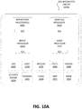
FIG. 10A illustrates exemplary integrated circuits and associated graphics processors, according to embodiments described herein for multi-level image reconstruction;
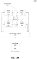
FIGS. 10B-10C illustrate exemplary integrated circuits and associated graphics processors, according to at least one embodiment, to support and/or to enable for multi-level image reconstruction;
FIGS. 10D-10E illustrate additional exemplary graphics processor logic, according to at least one embodiment, to support and/or to enable for multi-level image reconstruction;
FIG. 11A is a block diagram illustrating a computing system to support and/or to enable for multi-level image reconstruction according to at least one embodiment;
FIG. 11B illustrates a parallel processor to support and/or to enable for multi-level image reconstruction according to at least one embodiment;
FIG. 11C is a block diagram of a partition unit according to at least one embodiment;
FIG. 11D shows a graphics multiprocessor used for multi-level image reconstruction according to at least one embodiment;
FIG. 11E shows a graphics multiprocessor according to at least one embodiment;
FIG. 12A illustrates a multi-GPU computing system, according to at least one embodiment;
FIG. 12B is a block diagram of a graphics processor, according to at least one embodiment;
FIG. 13 is a block diagram illustrating micro-architecture for a processor that may include logic circuits to perform instructions, according to at least one embodiment;
FIG. 14 illustrates a deep learning application processor, according to at least one embodiment;
FIG. 15 is a block diagram of a neuromorphic processor, according to at least one embodiment;
FIG. 16A is a block diagram of a processing system, according to at least one embodiment;
FIG. 16B is a block diagram of a processor having one or more processor cores, an integrated memory controller, and an integrated graphics processor, according to at least one embodiment;
FIG. 16C is a block diagram of hardware logic of a graphics processor core, according to at least one embodiment;
FIGS. 16D-16E illustrate thread execution logic including an array of processing elements of a graphics processor core according to at least one embodiment;
FIG. 17A illustrates a parallel processing unit, according to at least one embodiment;
FIG. 17B illustrates a general processing cluster, according to at least one embodiment;
FIG. 17C illustrates a memory partition unit of a parallel processing unit, in accordance with at least one embodiment; and
FIG. 17D illustrates a streaming multi-processor, according to at least one embodiment.
DETAILED DESCRIPTION
Radiation is provided from a source, such as an x-ray source, and data is obtained from projections of the radiation through a tissue or object using one or more detectors. The detector may include an array of detectors and reference to the detector may be taken as reference to the array of detectors unless stated otherwise. The data is obtained at different angles by moving the source and a detector or using multiple detectors for different source angles. The movement is around a subject in a medical application or around an object. The movement may be at a region of interest (ROI) of the subject or the object, for instance. The data from the different angles at each lateral location around which the movement occurs are combined and represent slices of the data. The data, when combined, may be represented as an image volume having width, height, and depth. A transformation process may be applied to find pixel values for the image volume, for instance, at each intersection of the data of a slice at the different angles included in the slice. The pixel values, in at least one embodiment, may be intensities of light for pixels at the different angular positions for a lateral position of the source and the detector. When completed, the transformation process generates an image representing a backprojection of the data across the angles and may include lateral features as well.
Furthermore, different than backprojection, which is a non-iterative reconstruction, an iterative reconstruction is also available to reconstruct the image. In the iterative reconstruction, the data obtained by the detectors may be compared with simulated data established initially for the tissue (or features underlying the tissue) using the same source and assuming parameters for passing the radiation through the tissue to the detectors. Difference between the projected data and the simulated data may be treated as an error fed back to the simulated data to require convergence between the two types of data at every pixel or blocks of pixels. As this is an iterative process, the result after convergence of the difference is the image reconstructed with features underlying the tissue or the object. Iterative reconstruction has been shown to have lesser noise (e.g., signal-to-noise ratio (SNR) and contrast-to-noise ratio (CNR)) than non-iterative reconstruction, such as backprojection or its variants.
Computation for the iteration is complex, time consuming, and processor-intensive. Moreover, at least in medical applications, patients may be required to endure long exposure times to radiation. The present disclosure uses a multi-GPU or multi-processor architecture to determine optimal initialization for the image reconstruction process and reduces the number of iterations required to converge a dataset. Multiple levels of compression are used in an iteration process according to at least one embodiment of the present disclosure. Optimal initialization is a goal of the iteration process of the present disclosure. Optimal initialization ensures that the simulated data is initially as close to the data obtained from the detectors.
In at least one embodiment, the simulated data is obtained by iteratively testing a slice of data that represents a most compressed level. The most compressed level, in turn, has a least amount of the data but represents significant features in a dataset. Then, using different parameters and algorithms in each of multiple GPUs or processors, during the iterative testing, it is possible to select at least a parameter and at least an algorithm that achieves convergence for the slice of data. In at least one embodiment, the simulated data based on arbitrary values is adjusted iteratively based in part on a difference, after each iteration cycle, in the arbitrary values to measured values in the slice of data. The resulting adjusted simulated data is an image volume that may be used as an initializer image in subsequent levels of compression. As the level of compression is the most compressed in this instance, there are fewer data points to achieve convergence. The parameter and the algorithm for the most compressed level may be used with subsequent levels having lower compression data points in the data. This process represents a neural network application for learning of the parameter and the algorithm suited for different levels of compression, in an instance. In at least one embodiment, each level of compression may be considered as a hidden layer associated with a neural network. The upsampled output from each level of compression being fed into a subsequent algorithm, as an initializer image, represents a feed forward propagation, for instance, in the neural network.
As the data in the lower compressed levels are a version of the data in the higher compressed levels, with more information, the parameter and the algorithm may be expected to achieve convergence at the lower and subsequent levels of compression. When completed, because the simulated data is adjusted, the number of iterations to coverage an error or difference between the simulated data and the projected data at each subsequent level is reduced. Optimal initialization may be, therefore, represented by one or more of the selected algorithm having a selected parameter and the initializer image generated in a first level (highest level) of compression and used as a basis for subsequent initializer images in respective iterative processes of the lower levels of compression.
As such, a system and a computer-implemented method for reconstruction of an image are disclosed according to at least one embodiment herein. Data is obtained from radiation through a tissue as described throughout this disclosure. Levels of compression are established for the data by at least distributing (e.g., allocating, organizing, and selecting) data points within the data into subsets of data. The subsets may represent slices of the data obtained at different angles of specific cross-sections or lateral positions of the tissue for example. Further, the subsets include data points representing individual data items from within the data. The levels of compression include increasing amounts of data points within the subsets of the data. In at least one embodiment, a first level of compression may be a highest compression level relative to a second or a subsequent level of compression. So the first level of compression, and in turn, a first subset of the subsets of the data, has the least amount of data points. This may be achieved by selective gathering of the data so that alternate detectors, which forms part of array of detectors and which is wholly functioning as a singular detector of a tomography system, provide the first subset of the data. Alternatively, a portion of the data is allocated to the first subset of the data. In this manner of data collection, it is possible to reduce the data points gathered in each slice of data, for instance. As such, the first level of compression has lesser data, but also has the most pertinent data that is largely representative of one or more slices (or one or more subsets) of data gathered during the radiation phase of the tomography process.
At least one reconstruction parameter and a reconstruction algorithm are established for the first level of compression. As the first level of compression represents the highest compression level for the data, it also represents a smaller subset of the data that may be converged in an iterative process using simulated data from a simulated dataset. In at least one embodiment, an algorithm for the reconstruction may be determined by testing one or more iterative or non-iterative algorithms using subsets of the data from the first level of compression. The testing may be performed in parallel using the multiple GPUs of the multi-GPU architecture. When convergence is achieved in one of the tests using one of the available algorithms, an amount of data points in the subsets of data used to cause the convergence is noted. For non-iterative algorithms, a resulting image volume after filtering to remove blurs and other noise may be used to determine if the non-iterative algorithm and the filtering that was applied may be used to establish the reconstruction algorithm and the at least one reconstruction parameter. As the amount may be a test amount, the amount may be extrapolated or upsampled for use with the entire subset of data, for instance. The amount of data points in the first subset of the data may be taken as an optimal amount for the first subset and for subsequent subsets of the data representing the first and the subsequent levels of compression. The amount of data points then represents a reconstruction parameter established for the reconstruction phase for an image of the underlying features to the tissue. The algorithm used to achieve the convergence with the optimal amount of data points is taken as the reconstruction algorithm for the reconstruction phase.
Alternatively, a non-iterative algorithm, such as FBP, may be used as the reconstruction algorithm instead of an iterative algorithm. In the case of a non-iterative algorithm, the use of a specific filter to prevent blurring may be considered an applicable reconstruction parameter. The reconstruction algorithm and the reconstruction parameter are used for the entire subset of the data representing the first level of compression. First image volumes, corresponding to iterations involving the first level of compression or corresponding to intermediate image volumes in the applied non-iterative algorithm, may be generated in each of the iterations or to steps associated with each level of compression. A determination may be made that one of the first image volumes generated during the iteration satisfies a predetermined criteria. The predetermined criteria, in at least one embodiment, may be that the first image volume is generated once the convergence is achieved or is an image volume generated after FBP is performed using the first subset of data. This determination qualifies the first image volume as a first initializer image volume for a second level of compression.
The second level of compression has a higher amount of data points in the data than the first level of compression. As such, an upsampling step is performed to upsample the first initializer image volume to requirements of the second level of compression. In at least one embodiment, the upsampling step may insert singular values, such as applying zeros (Os), to fill spaces in an array or dataset, but an extrapolation, interpolation, or intrapolation of neighboring values from a dataset of the current level of compression may be also used to achieve a similar number of data points as a subsequent level of compression. In a similar manner, the present disclosure requires iterating through individual levels remaining of the levels of compression, after the second level of compression. An image volume from a prior level is used with a subsequent level of the individual levels after upsampling from each prior level to the subsequent level. Further, the iteration may at least start for a subsequent level using the at least one reconstruction parameter. As such, the image volume of the prior level being upsampled becomes a subsequent initializer image volume for the subsequent level. A final image volume is generated after the iteration. The final image volume demonstrates a convergence with a simulated image volume to enable reconstruction of the image of the tissue.
Multi-level reconstruction performed in a multi-GPU architecture ensures that core and computationally intensive iterations are performed in a highest compressed space and may be performed among the multiple GPUs of the multi-GPU architecture. The reconstruction parameter, the reconstruction algorithm, and/or the first image volume established and confirmed in the highest compressed space, using the multi-GPU architecture, may be stored as an optimal output to be used with data from subsequent levels of compression. Furthermore, the first image volume is also an optimal output representing significant features of the data. The multi-level reconstruction herein may be repeated until the original reconstruction level (e.g., non-compressed space) is reached at which point the initializer, being continuously optimized is additionally, an optimum initializer from which the image reconstruction occurs. The disclosure, therefore, enables determination of the optimal initializer for reconstruction of images, and particularly for tomography systems. When multiple algorithms and associated parameters exist, they represent a most appropriate sequencing and weighing of several algorithms that may be obtained in the most compressed space of a multi-GPU architecture. The most appropriate sequencing and the weighing, representing the established and confirmed reconstruction algorithm and parameter, can be used for final image generation in the original reconstruction space.
FIG. 1 is a block diagram of an example tomography system 100 incorporating the multi-level reconstruction using multiple Graphical Processing Units (GPUs) for a medical application, according to at least one embodiment of the disclosure. A person of ordinary skill reading the present disclosure would recognize the application of at least one embodiment of the present disclosure as-is, with modifications, or in combination with embodiments herein, to establish a similar multi-level image reconstruction for other imaging technologies. In at least one embodiment, other than tomography, any imaging system capable of sequencing images in a compression space may benefit from the present system and method. In FIG. 1, a subject 106 or an object may be arranged to face a source of radiation 102. In particular, a region of interest (ROI) 106A of the subject 106 may be exposed to the source of radiation 102. In at least one embodiment, the source of radiation 102 is an x-ray source generating a parallel beam, a cone beam, or fan beam projection to the ROI. Data associated with the ROI is captured or obtained at different angles around the subject 106A, at a lateral cross-section, by moving one or more of the source 102 and/or a detector 108. Detector 108 may be stationary and may be formed as a detector array including multiple detectors (or sub-detectors) for capturing data at different source angles of the source of radiation 102, around the subject 106A, in at least one embodiment of the disclosure.
One or more system controllers 110 may be provided to control movement of the source 102 and of the detector 108, if the detector is configured for movement. A system controller 110 may control movement of the source 102 using input signals to the source 102. The input may include timing and power signals. A processing module 114 may determine the angles and the power of radiation, among other requirements from the source 102 and from the detector 108, and may provide instructions for the system controller 110 to make the requirement movements and adjustments to collect the data associated with the ROI 106A. The timing and power signals may be also provided to the source 102 and may also be provided to detector 108, so that any relative motion between the source and the detector is synchronized and properly achieved. The detector 108 provides the data from the different angles for processing. In at least one embodiment, the data is obtained at a reconstruction module 112 and may be also obtained in the processing module 114. The data may then be combined using a transformation process applied to different pixel values in the data, for instance, with support of multiple GPUs 112A in the reconstruction module 112. In at least one embodiment, the data may be obtained and stored in data arrays, from which, a slice, such as illustrated by reference numeral 118, is determined. The slice is part of an image volume representing a cross-section of features within the ROI, for instance. In at least one embodiment, the data may be obtained directly into slices, also configured as arrays, but which are marked as representing certain lateral cross-sections of the subject 106.
In at least one embodiment, a reconstructed image is generated from the reconstruction module 112 and provided via the processing module 114 to the input/output (I/O) module 116. The reconstructed image includes representations of internal organs as features underlying a tissue and within a cross-sectional view of a torso 106A (in at least an embodiment, the example ROI). This reconstructed image may be presented as a computerized tomography (CT) output from the system 100. In at least one embodiment, although a two-dimensional (2D) representation is illustrated, the data may support three-dimensional (3D) representations. In at least one embodiment, the image from the I/O module 116 includes a representation of an ROI of an object. In at least one embodiment, in order to analyze the ROI, such as to measure dimensions, shape, or other such aspects, a portion of an image corresponding to the ROI may be determined and used to generate initial values that may be extrapolated depending on features from the ROI. The I/O module 116 may be any appropriate electronic and/or computing devices enabling a user to generate and send requests for the tomography system. In at least one embodiment, the I/O module 116 may include desktop computers, notebook computers, computer servers, smartphones, tablet computers, gaming consoles (portable or otherwise), computer processors, computing logic, and set-top boxes. In at least one embodiment, the processing module 114 communicates with the I/O module 116 via any appropriate network for communicating requests or other data, as may include the Internet, an intranet, an Ethernet, a cellular network, a local area network (LAN), a network of direct wireless connections among peers, and so on.
In at least one embodiment, a user can indicate a set of points corresponding to a surface of an object or subject to define the ROI. In at least one embodiment, the data from the detector 108 may include extreme points indicated for the object or the subject. In at least one embodiment, there may be a top-most point, a bottom-most point, a left-most point, and a right-most point for establishing the ROI of the image or the subject. In at least one embodiment, if data obtained is for an image in 3D, the above-referenced points may include a front-most and a back-most (or posterior and anterior, etc.) points as well. In at least one embodiment, additional points may be included. These points may be referred to as extreme points as they indicate at least extreme positions of a representation expected for an ROI (e.g., ROI 106A) of an object or subject 106 along certain dimensions. In at least one embodiment, the above-referenced points can be used to determine segmentation for the subject 106 or the object.
In at least one embodiment, any portion of instructions for the various modules 110-114 and/or data storage may be internal or external to one or more processors or other hardware logic devices or circuits, such as GPUs 112A or a CPU in module 114. In at least one embodiment, instructions and/or code and/or data storage may be part of a cache memory (or other on-chip or off-chip data storage, including a processor's L1, L2, or L3 cache or system memory), dynamic randomly addressable memory (“DRAM”), static randomly addressable memory (“SRAM”), non-volatile memory (e.g., Flash memory), or other storage. The instructions and/or code within any of the above-referenced storage components form a non-transitory computer-readable media that may be used with a processor to cause the instructions and/or the code to execute and perform the processes described throughout this disclosure. In at least one embodiment, choice of whether instructions and/or code and/or data storage is internal or external to a processor, for example, or included of DRAM, SRAM, Flash or some other storage type may depend on available storage on-chip versus off-chip, latency requirements of training and/or inferencing functions being performed, batch size of data used in inferencing and/or training of a self-learning networks, or some combination of these factors.
FIG. 2 is a feature diagram of certain steps 200 followed in a tomography process that is subject to processing steps described in at least one embodiment of this disclosure. The transmission of radiation through an ROI causes projection data, simply referred to herein as data 202. The data 202 is captured, obtained, or generated from detectors referenced in FIG. 1. The data represents remnants of the radiation after tissue or object-based absorption, reflection, or refraction. The data is illustrated as rows of scanned information, which may be pixel brightness values, for instance. This may represent sampled and quantized data for instance, from which the image is reconstructed after processing steps disclosed herein are completed. In at least one embodiment, the data is represented in rows and/or columns of multiple arrays 202 including the representation of features within the ROI. Each array 202 represents one or more views of the features within the ROI from an angle at a lateral cross-section. Some tomographic systems obtain views at 1° increments, but other larger increments are also possible. The source may be subject to parameter variation to generate the required intensity of radiation to perform the tomography process. Further, the source current (mA) may be a parameter available for adjustment depending on the tomography process requirements. In at least one embodiment, voltage (kV) and the source current (mA) values may be adjusted depending on the subject (also organs, fat content, water content, etc.), the object, or the ROI at issue. In at least one embodiment, for an x-ray source, the mA multiplied with a time of rotation for the source may be used to determine x-ray photos for each or a total number of scans generated as the source rotates. As such, an aspect of the present disclosure is the use of the multi-level reconstruction of images in x-ray imaging. For tomography processes, the photons required for a tomography image may be understood as proportional to the mA value.
Further, a type of projection of the radiation from the source is another parameter that may be adjusted in the tomography process. FIG. 1 illustrates a cone beam projection, but a parallel beam projection, an axial source fan projection, and a detector fan projection also benefit from the present disclosure for image reconstruction. In a further aspect of the present disclosure, beam filtration may be applied to shape the energy distribution across the ROI, but a beam collimator may be used on the detector side to reduce scatter of the beam radiation, for instance. In at least one embodiment, each of the slices of data includes a row-by-column spread of pixel values, and may include a thickness value. In at least one embodiment, a slice of the data from the projection data may include 512×512 pixels and a thickness (or width) of 8 or 16 bits. A combination of each data point in the 512×512 pixel distribution and a thickness at the data point represents a voxel. Each of the detectors in a multiple detector configuration may obtain a slice of data or different angles of a single slice of data, as the source (and or detector) moves around the ROI. Preprocessing may be performed in module 204. For instance, steps may be taken to convert exponential values from the detector to a linear value and to adjust for polychromatic values from the detector.
Filtered backprojection (FBP) may be performed in module 206. FBP is one example algorithm that may be used to find slices for an image volume from the arrays 202. There are other algorithms, as discussed elsewhere in this disclosure that may be used instead of FBP. A goal of FBP is to determine slices of data (such as slice 118), from the multiple values in arrays 202, that correspond to rays through different parts of an ROI at different angles. Different slices including the different angles (from the different views of the ROI) may be combined to provide an image volume. In at least one embodiment, taking the horizontal position of subject 106, the slice 118 includes different views for a cross-section that is obtained from a configuration of the source 102 and the detector 108 being opposite each other with the subject 106 in between. As noted elsewhere in this disclosure, the source 102 and the detector 108 are in relative motion to enable a 360° capture of features at a cross-section of the ROI. In at least one embodiment, the slices may be determined from the different views using the data in the arrays 202. Values for the views may be obtained by summing all the pixels in cells along a first angle (first view) of the available angles to arrive at a one dimensional (1D) collection of values for the first angle (first view). Then slices may be obtained by a combination of the 1D values according to various algorithmic process, such as explained in further detail below. In at least one embodiment, a slice may be formed from an iterative reconstruction technique, although some other computationally intensive technique, such as simultaneous linear equations may be used.
In at least one embodiment, the iterative reconstruction technique may be applied by setting pixels in a predefined slice (e.g., simulated or expected data) to have starting pixel values. As measured or actual values (different from the simulated or expected data) from a scan of an ROI do not have a reference point, the use of the iterative reconstruction technique provides such a reference by starting with arbitrary values, for instance, that are adjusted in an iterative manner (described below) to result in an accurate slice for enabling image reconstructing of the ROI. The starting pixel values may be the arbitrary values representing simulated, neutral, or expected data, for instance. The expected data may be theoretically determined for a slice for a specific cross-section, for instance. In at least one embodiment, known components of tissue and their known response to radiation may be used to determine the starting pixel values in the slice. Then, actual or measured data that includes actual values that are preprocessed from arrays 202, and that are obtained by summing pixel values along an angle (as described above) may be used to compare against the starting pixel values of corresponding cells of the predefined slice. The comparison may be a statistical comparison, such as to determine an error or difference between the starting pixel values and the actual values, either for all values of the cells collectively, individual values of individual cells, a maxima value from the cells collectively, a minima value from the cells collectively, or other statistically significant values. The error or difference may be used to correct the starting pixel value (or all the values of the cells collectively), and the process is repeated for each predefined slice using the actual values till the error is the least or does not exist, representing a convergence of the iteration process. The predefined slices are transformed, at the end of the iteration process, to the slices that form an image volume used to reconstruct an image showing features underlying the ROI.
Iteration processes are also computationally intensive. As a result, the lesser the iterations, the faster a tomography system is able to process data received and to display images reconstructed from the data. To reduce the number of iterations of the above-described process, it is best suited if a tomography system is able to start with predefined slices having a close starting pixel values to the actual values. As a result, the error is small in the beginning and continues to get smaller as the iteration progresses, but requires a lesser number of iterations to result in the reconstructed image. The FBP process of module 206 is different than the iterative process. Initially, a simple backprojection process obtains each view from the actual values that are preprocessed from arrays 202 and that are obtained by sum of pixel values along an angle. The actual values are adjusted along the angle to a singular value. A final backprojected image is formed from a sum or combination of the backprojected views. FBP is a process that performs additional features over the simple backprojection process. In FBP, each view is filtered first to address blurring issues that may exist in the simple backprojection process. In at least one embodiment, each of the 1D views undergoes convolution with a 1D filter to create filtered views. The filtered views are backprojected in module 206 to provide an image volume 208 that include the slices. The image volume 208 is used to render the reconstructed image 210.
As image reconstruction is a time-consuming process, an appropriate initializer image volume having starting pixel values that are as close to the actual values can aid in fast convergence of the iterative process. The process to determine the appropriate initializer image volume may be challenging. The present disclosure compresses the original reconstruction space to several levels. Reconstruction of an image volume is performed in the lowest level of compression on a multi-GPU architecture with different reconstruction parameters and using a singular algorithm or using different reconstruction algorithms. Based on predetermined or predefined criteria, a best image volume is selected from the reconstruction at the lowest level of compression. The selected image volume is upsampled to be used as an initializer image volume for one or more subsequent levels of compression that represent lower levels of compression. This process is iterated on the multi-GPU architecture until the initializer image volume for the original reconstruction space is determined. An image may be reconstructed from the initializer image volume for the original reconstruction space. The present process benefits because it does not iterate in an original reconstruction space that is uncompressed for the large part. With the iteration occurring in a compressed space and then improved upon, the initializer image volume of the lowest (or first) level of compression is improved as it grows through the levels of compression till the original (or uncompressed) space is reached. As such, the present process enables selection of a suitable algorithm along with associated parameters, such as sequence and weights for finding an appropriate initializer image volume.
FIG. 3 is a feature diagram of an example multi-level tomography process 300 to reconstruct an image, according to at least one embodiment of this disclosure. Data in arrays 302 is obtained from radiation through a tissue as previously noted. Levels of compression are established in module 304. The levels of compression include subsets having increasing amounts of data points of the data. Each subset may be associated with a slice of data having different views. In at least one embodiment, a first level of compression may be a highest compression level relative to a second or a subsequent level of compression. This may be achieved by selective gathering of data around different views at a specific cross-section of a subject, so that only alternate detectors forming part of array of detectors provide the subset of data for that slice. Alternatively, the data from select detectors of the array of detectors is used even though all the detectors are collecting the data, thereby reducing the amount of the data points used in the processing stages. These methods reduce the data points gathered in each slice of the data, for instance. A person of ordinary skill would also recognize upon reading this disclosure that deep learning techniques may be used to fill data voids caused by alternating the detectors. This process and a system based thereupon, apart from benefiting because of faster processing times, also benefits because of reduced cost of scanning for the data. Deep learning may be advanced using any appropriate learning network, such as a deep neural network (DNN), a recurrent neural network (RNN) or a convolutional neural network (CNN). Once a network is trained and successfully evaluated to recognize data within a subset or a slice, for instance, the trained network can provide similar representative data for using with the collected data.
In at least one embodiment, a computer-implemented method is disclosed for using neural networks to reconstruct images. The method includes establishing one or more levels of compression for image data from a region of interest (ROI). An image volume may be generated from a first level of compression using a subset of the image data. One or more neural networks, such as the above example neural networks, may be used to generate subsequent image volumes for one or more hidden layers representing subsequent levels of the one or more levels of compression. An image that is associated with features underlying the ROI is generated from a final image volume of the one or more neural networks. Further, when the image volume of the first level of compression is determined as satisfying a predetermined criteria, it may be qualified for use with the one or more neural networks, as an initializer image, for instance. This may be achieved via filtered backprojection (FBP) applied to confirm the quality of the image volume at each level (or layer of the neural network). In a further aspect, the processing in the first level of compression (and in subsequent levels of compression) may occur simultaneously to determine at least a parameter and an algorithm to use with the neural network. In at least one embodiment, the subset of the image data may be processed simultaneously according to at least one parameter and using predetermined algorithms forming the one or more neural networks. The processing is performed simultaneously in multiple Graphical Processing Units (GPUs) of a multi-GPU architecture to determine that a parameter is applicable to achieve constrained optimization in the first level of compression. Thereafter the parameter may be applied in at least one of the subsequent levels of the one or more neural networks.
In at least one embodiment, the upsampling step used in this disclosure may be one way of providing comparable datasets for processing. Extrapolation, interpolation, or intrapolation may be used to adjust datasets to a required number of data points for processing at each subsequent level of processing. In at least one embodiment, because data may be obtained from alternate detectors, the data may be smoother because the data includes extrapolated, interpolated, or intrapolated data from neighboring pixels or groups of pixels. The extrapolated, interpolated, or intrapolated data may be closer in value to the real values in the measured or actual data compared with zero values that may be the case with upsampling. Unless stated otherwise, the present disclosure may use either of upsampling, extrapolation, interpolation, or intrapolation, to achieve datasets for a second and for each subsequent level of compression.
The geometry modelling module 304 is used to determine appropriate spatial and geometric features for the tomography system. The image volume is formed of voxels that are part of slices across one or more cross-sections of a subject. Each slice is divided into a matrix of voxels. As such, the voxels provide data to enable the reconstruction of an image that includes features within an ROI of the body. An appropriate geometry is required to be used for each ROI depending on the subject and the ROI at issue. In at least one embodiment, size constraints and organ constraints may be useful to define the geometry for the levels of compression so that data is appropriately distributed depending on the geometry of the organs under scan. Further, the simulated data having arbitrary values used in the iterative process may be adjusted to include data points (e.g., sparsified) for an expected organ shape. The simulated data may be represented in the levels of compression and is adjusted during the iteration process. Further, size of the voxels may have an influence on aspects of the geometry, including causing blurring and additional noise in the data. As a result, for each slice, a field of view, slice thickness, and number of pixels or voxels is established to achieve desired reconstruction of an image having features from the ROI at issue. Module 304 enables geometric modelling in consideration of these requirements but also by determining the levels of compression intended for the subject and/or intended for the ROI. In at least one embodiment, depending on one or more organs requiring a scan in the ROI at issue, the levels of compression may change based in part on the field of view, the slice thickness, and the number of pixels or voxels required to enable image reconstruction and convergence of an iterative process that uses the present system and method.
The first level of compression is the highest compression level and has a least amount of data points among the other levels of compression from the geometry modelling module 304. When it is determined to organize data into the level of compression, the detectors may be instructed to collect data in a certain way. Module 304 may be bidirectional with the system controller discussed in FIG. 1, for instance. The first level of compression also has the most pertinent data that is largely representative of one or more slices (or one or more subsets) of the data gathered during the radiation phase of the tomography process. As the data includes the subsets, a reference to a least amount of the subsets may be used interchangeably to refer to the least amount of the data points. In at least one embodiment, the first level of compression is determined from subsets of the data (with the least amount of data points in the data), including based in part on how the data is collected and the configuration of active detectors during data collection. In at least one embodiment, a subset of data that skips groups of neighboring data may have the most pertinent or distinguishing features because the subset of data is determined at a higher level viewpoint and minute differences in boundaries between color and brightness, at lower level viewpoints, may be ignored. In at least one embodiment, using a configuration where select detectors in the detector array are active, instead of activating all the detectors, may result in a lesser amount of data points, but also accommodates the most pertinent and distinguishing features in the ROI.
In the optimal parameterization module 308, at least one reconstruction parameter and a reconstruction algorithm are established for the first level of compression. The reconstruction parameter and the reconstruction algorithm are provided from the optimal parameterization module 306 to the core reconstruction module 308. In at least one embodiment, one of many available algorithms may be used to test an amount of a subset of the data (e.g., a subset of data associated with the first level of compression). In at least one embodiment, a regularized ordered subset expectation maximization (OSEM) algorithm is an available algorithm that may be used to find an optimal number of data points in a subset of the data required to achieve convergence. The OSEM may be used with regularization parameters. The number of iterations, computations, or cycles required to determine the appropriate regularization parameters may be excessive, but using the lower number of data points in the first level of compression, this exercise may be more manageable. When two or more such regularization parameters are obtained, the parameters and the number of iterations may be applied to subsequent levels of compression to converge the data at respective subsequent levels of compression. When the two or more such regularization parameters are used in the subsequent levels of compression and when it is determined that the two or more such regularization parameters may benefit from revisions to create two or more revised regularization parameters, the revised regularization parameters may be used with the algorithm and with subsequent levels of compression after the revision. Furthermore, it is also possible to use a different regularization or other parameters instead of the previously used parameters for the subsequent levels of compression for the applied algorithm. This may depend on, for instance, whether the subsequent levels of compression result in optimization by the iterative process of the applied algorithm.
Other iterative algorithms and their associated parameters may be used to test an amount of the subset of the data in multiple GPUs of the multi-GPU architecture. With thousands of cores, GPUs are designed to handle substantial parallel workloads. In the present disclosure, parts of the processes explained throughout this disclosure are performed on multiple GPUs that communicate in real-time with a processing module (such as module 114 of FIG. 1) that includes a central processing unit (CPU). Alternatively, the GPUs (such as GPUs 112A of module 112 in FIG. 1) may be used for perform the entirety of the processes disclosed herein for multi-level image reconstruction. Because GPUs have different performance and cost characteristics than CPUs, however, running a service that offloads part of the processes to a GPU can require it to be designed differently and efficiently than a plainly CPU-based service. In at least one embodiment, a GPU may be able to process thousands of parameters and algorithms concurrently via different hardware threads. In at least one embodiment, the iterative processing to select a parameter and one or more algorithms occurs simultaneously in the first level of compression using multiple Graphical Processing Units (GPUs) of a multi-GPU architecture to test different parameters and different algorithms using one or more of the subset of the image data captured of the ROI. When constrained optimization is achieved, including, for example, a convergence of the iterative processing for one of a parameter and algorithm combination, in the first level of compression, then the process is stopped and the parameter and the algorithm may be used for the entire data of the first level and for the subsequent levels of compression.
The optimal number of data points is one of many other regularization parameters that may be used as a reconstruction parameter in the first level of compression. In at least one embodiment, a test may be first applied to determine an iterative convergence of a test portion of the subset of the data associated with the first level of compression. The test may be conducted against simulated or expected data, as reference. A result of the test is a convergence that is achieved and that represents an optimal amount of the data points required by the algorithm to achieve convergence. As such, the algorithm may be established as the reconstruction algorithm and the optimal amount of the subset of the data may be established as the at least one reconstruction parameter for the first level of compression. In at least one embodiment, the test described above may be performed using the entire subset of data associated with the first level of compression. In at least one embodiment of the iterative process, an error is generated after each iteration cycle, by comparison of at least a portion of the subset of the data against simulated or expected data, may be applied to increment or decrement values in the simulated or expected data. Eventually the error becomes smaller as the iteration cycles increase and until the simulated or expected data converges with the subset of the data associated with the first level of compression.
As the first level of compression represents the highest compression level for the data, the subset of the data for the first level of compression includes a least amount of the data points compared with subsets of the data for the subsequent levels of compression. Once the reconstruction algorithm and reconstruction parameter are established, this information may be stored in the optimal parameterization module 306. The core reconstruction module 308 processes the entire subset of data of the first level of compression using the established reconstruction algorithm and the established reconstruction parameter. First image volumes are determined at the end of each iteration for the first level of compression using the established reconstruction algorithm and the established reconstruction parameter. When the test is to a portion of the subset of the data associated with the first level of compression, then the established reconstruction algorithm that has achieved convergence with simulated or expected data using the test portion of the subset is expected to also achieve convergence with the entire subset by extrapolation, interpolation or upsampling. A determination may be made, once convergence is achieved, that a first image volume from the first image volumes satisfies a predetermined criteria. The predetermined criteria, in an aspect, may be that the first image volume is generated after the convergence is achieved or at the time of convergence. In at least one embodiment, the first image volume is the image volume of an iterative cycle demonstrating the convergence, which represents a constrained optimization in the first level of compression. This determination qualifies the first image volume as a first initializer image volume for a second level of compression. The first image volume may be stored in the initializer module block 310 for use with a subsequent level of compression.
The second level of compression has a higher amount of data points than the first level of compression and is a lower level of compression than the first level of compression. As such, an upsampling step is applied in the core reconstruction module 308 to upsample the first initializer image volume to requirements of the second level of compression. In a similar manner, the present disclosure requires iterating through individual levels remaining of the levels of compression, after the second level of compression. This is performed in the core reconstruction module 308, with the initializer module 310 storing initializer images 310A after or when convergence is achieved in each level of compression. An image volume from a prior level is used with a subsequent level of the individual levels after upsampling from each prior level to the subsequent level. Further, the iteration may at least start for a subsequent level using the at least one reconstruction parameter. As such, the image volume of the prior level being upsampled becomes a subsequent initializer image volume for the subsequent level. A final image volume 312 is generated after the iteration. The final image volume 312 demonstrates a convergence with a simulated image volume to enable reconstruction of the image 312 of features underlying the tissue.
In addition, for a given set of algorithms and their related parameters, the present disclosure is able to use the different levels of compression representing different datasets having a different number of data points to determine which of the parameters are suited to respective ones of the datasets. Thereafter, it is possible to use only certain parameters and certain algorithms on certain datasets. This may be an experimental process to determine, before a tomography process, what algorithm and parameters best suit a scan of an expected organ (versus other organs or objects, for instance).
FIG. 4 is a feature diagram illustrating example computation features 400 within each level of a multi-level tomography process to reconstruct an image using multiple-GPUs in accordance with at least one embodiment of this disclosure. Levels of compression may be established before or after the data is captured. The levels of compression may indicate how data is collected and stored for processing. In at least one embodiment, if the detector arrays are configured to provide data from alternating detectors of the detector array, then the data may be captured after the levels of compression dictating how the for the data, the data may be received from the detector are stored in data arrays as previously discussed. When a tomography system is configured to selectively use data from the data arrays after all the detectors provide data, then the levels of compression are established after the data is captured. In at least one embodiment, the levels of compressions are based in part on the geometry of the ROI. The geometry may change as the detectors move to a different cross-section or slice to cover the ROI. The geometry may also change depending on the organs at issue within different portions of the ROI. In at least one embodiment, blocks 402A-402N include the geometry established for different levels of compression, which is illustrated as space level 1 (geometry 1) to space level N (geometry N).
Based in part on the geometry, the core reconstruction progresses first with core reconstruction 1 402B. A core reconstruction 1 block 402B includes instructions to perform a first iterative process for a subset of the data representing a first level of compression provided from the block 402A. The first iterative process uses parameters associated with one or more algorithms selected for the first level of compression to generate a first dataset represented by the block 402B entitled reconstruction volume 1. The parameters and the one or more algorithms are selected in a similar manner as discussed with respect to aspects in FIGS. 2, 4. The first dataset may be the first initializer image volume for the first level of compression. As previously discussed, the first dataset is upsampled, via block 408A, so that it has sufficient data for a slice that matches the size of a second slice of the data included in the block 404B entitled core reconstruction 2. The block 404B receives the second slice representing a second level of compression from the block 402B entitled space level 2 (geometry 2). As previously described, the same parameters and algorithm as the first level of compression may be used here because it was previously selected for being able to iterate the most significant features at the highest level of compression. Alternatively, different parameters and a different algorithm may be used by first testing a portion of a second subset of data from the block 402B. The different parameters may be wholly different than the parameter previously used for the first or second subset of data, but may also be an improvement (e.g., reducing the number of iterations, in at least one embodiment) over the parameter previously used. As described elsewhere herein, a parameter may be a number of cycles to achieve optimal performance (e.g., constrained optimization) for the algorithm or may be a least number of data points required to achieve the optimal performance for the algorithm. So the improvement may be to reduce the number of cycles or reduce the number of data points required in a subsequent level of compression to achieve the optimal performance for the algorithm in the subsequent level of compression. As previously described elsewhere in this disclosure, the testing may be progressed in multiple GPUs till convergence is attained in at least one of available algorithms that process the portion of the second subset of data. Then the at least one of the available algorithms becomes the reconstruction algorithm for the second level of compression, along with at least an associated parameter for iterative processing of the entire second subset of data from block 402B.
Block 406B illustrates an output of the core reconstruction 2 block 404B. The output 406B is a second dataset that may be a second initializer image volume for the second level of compression. As in the case of block 408A, the second initializer image volume is upsampled to include sufficient data in an associated slice that can be used with a lower level of compression than the second level of compression. The process is repeated till block 402N is used to select geometry in an uncompressed space. Block 404N performs core reconstruction using the N−1 initializer image volume upsampled via block 408N−1 from a prior level of compression. The final image volume N in block 406N represents the image volume that is used for reconstruction of an image of the representation of the ROI.
FIG. 5 is a process flow 500 of steps available for multi-level tomography reconstruction of an image, according to at least one embodiment of this disclosure. In sub-process 502, data is obtained from radiation through a tissue. Sub-process 504 establishes levels of compression for the data. As described throughout this disclosure, the levels of compression may be first established followed by obtaining data according to sub-process 502, so that the data is obtained in the highest to the lowest levels of compression. As such, the data may be obtained first or subsequent to the establishment of the levels of compression. The levels of compression may be established by distributing the data into subsets of data. As such, the levels of compression include increasing amounts of data points within the subsets. Each of the subsets of the data may correspond to a slice of the data including different views at a cross-section of the tissue. The first level of compression, therefore, may have a least amount of data points among the subsets. Sub-process 506 establishes a reconstruction parameter and a reconstruction algorithm for a first level of compression.
Sub-process 508 performs a determining step to determine first image volumes using the reconstruction parameter and the reconstruction algorithm. Sub-process 510 determines a first image volume from the first image volumes. This may be done by verifying, via sub-process 512, that the first image volume satisfies a predetermined criterion to qualify the first image volume as a first initializer image volume for a second level of compression via sub-process 514. In at least one embodiment, the predetermined criteria may be that the first image volume is generated after iteration is complete and convergence is achieved for the level of compression at issue. The iteration otherwise continues via sub-process 510. Alternatively, for a non-iterative processing within the levels of compression, if a filter is applied using an FBP process and the resulting image volume has the least amount of blur, then the image volume may be used as an initializer image for the second level of compression via sub-process 514. The image volume is otherwise filtered via sub-process 510. Sub-process 516 upsamples the first initializer image volume to requirements of the second level of compression. This may include injecting insignificant data into cells of an appropriately sized array for the second level of compression, for instance.
Sub-process 518 demonstrates that process 500 performs at least sub-processes 508-516 iteratively. In at least one embodiment, sub-process 518 iterates through individual levels remaining of the levels of compression after the second level of compression. Sub-process 518 uses an image volume from a prior level as a subsequent initializer image volume for a subsequent level of the individual levels and uses the at least one reconstruction parameter. The image volume of the prior level is first upsampled to be the subsequent initializer image volume. Sub-process 520 generates a final image volume after the iteration. The final image volume is in convergence with a simulated image volume and enables reconstruction of the image of features underlying the tissue.
Data Center
FIG. 6A illustrates an example data center 600, in which at least one embodiment from FIGS. 1-5 may be used. In at least one embodiment, data center 600 includes a data center infrastructure layer 610, a framework layer 620, a software layer 630, and an application layer 640. In at least one embodiment, at least one embodiment described in respect to FIG. 1, such as features in components 110-116 may be performed inside or in collaboration with the example data center 600. In at least one embodiment, the image captured from detector 108 may be partly or fully processed in processing module 114 and reconstruction module 112, but may also be partly or fully processed in one or more of the components in the data center infrastructure layer 610. This enables high level computation to occur at high speed in dedicated computing environments that may not (or need not) be locally available.
In at least one embodiment, as in FIG. 6A, data center infrastructure layer 610 may include a resource orchestrator 612, grouped computing resources 614, and node computing resources (“node C.R.s”) 616(1)-616(N), where “N” represents any whole, positive integer. In at least one embodiment, node C.R.s 616(1)-616(N) may include, but are not limited to, any number of central processing units (“CPUs”) or other processors (including accelerators, field programmable gate arrays (FPGAs), graphics processors, etc.), memory devices (e.g., dynamic read-only memory), storage devices (e.g., solid state or disk drives), network input/output (“NW I/O”) devices, network switches, virtual machines (“VMs”), power modules, and cooling modules, etc. In at least one embodiment, one or more node C.R.s from among node C.R.s 616(1)-616(N) may be a server having one or more of above-mentioned computing resources.
In at least one embodiment, grouped computing resources 614 may include separate groupings of node C.R.s housed within one or more racks (not shown), or many racks housed in data centers at various geographical locations (also not shown). Separate groupings of node C.R.s within grouped computing resources 614 may include grouped compute, network, memory or storage resources that may be configured or allocated to support one or more workloads. In at least one embodiment, several node C.R.s including CPUs or processors may grouped within one or more racks to provide compute resources to support one or more workloads. In at least one embodiment, one or more racks may also include any number of power modules, cooling modules, and network switches, in any combination.
In at least one embodiment, resource orchestrator 612 may configure or otherwise control one or more node C.R.s 616(1)-616(N) and/or grouped computing resources 614. In at least one embodiment, resource orchestrator 612 may include a software design infrastructure (“SDI”) management entity for data center 600. In at least one embodiment, resource orchestrator may include hardware, software or some combination thereof.
In at least one embodiment, as shown in FIG. 6A, framework layer 620 includes a job scheduler 622, a configuration manager 624, a resource manager 626 and a distributed file system 628. In at least one embodiment, framework layer 620 may include a framework to support software 632 of software layer 630 and/or one or more application(s) 642 of application layer 640. In at least one embodiment, software 632 or application(s) 642 may respectively include web-based service software or applications, such as those provided by Amazon Web Services, Google Cloud and Microsoft Azure. In at least one embodiment, framework layer 620 may be, but is not limited to, a type of free and open-source software web application framework such as Apache Spark™ (hereinafter “Spark”) that may utilize distributed file system 628 for large-scale data processing (e.g., “big data”). In at least one embodiment, job scheduler 622 may include a Spark driver to facilitate scheduling of workloads supported by various layers of data center 600. In at least one embodiment, configuration manager 624 may be capable of configuring different layers such as software layer 630 and framework layer 620 including Spark and distributed file system 628 for supporting large-scale data processing. In at least one embodiment, resource manager 626 may be capable of managing clustered or grouped computing resources mapped to or allocated for support of distributed file system 628 and job scheduler 622. In at least one embodiment, clustered or grouped computing resources may include grouped computing resource 614 at data center infrastructure layer 610. In at least one embodiment, resource manager 626 may coordinate with resource orchestrator 612 to manage these mapped or allocated computing resources.
In at least one embodiment, software 632 included in software layer 630 may include software used by at least portions of node C.R.s 616(1)-616(N), grouped computing resources 614, and/or distributed file system 628 of framework layer 620. One or more types of software may include, but are not limited to, Internet web page search software, e-mail virus scan software, database software, and streaming video content software.
In at least one embodiment, application(s) 642 included in application layer 640 may include one or more types of applications used by at least portions of node C.R.s 616(1)-616(N), grouped computing resources 614, and/or distributed file system 628 of framework layer 620. One or more types of applications may include, but are not limited to, any number of a genomics application, a cognitive compute, and a machine learning application, including training or inferencing software, machine learning framework software (e.g., PyTorch, TensorFlow, Caffe, etc.) or other machine learning applications used in conjunction with one or more embodiments.
In at least one embodiment, any of configuration manager 624, resource manager 626, and resource orchestrator 612 may implement any number and type of self-modifying actions based on any amount and type of data acquired in any technically feasible fashion. In at least one embodiment, self-modifying actions may relieve a data center operator of data center 600 from making possibly bad configuration decisions and possibly avoiding underutilized and/or poor performing portions of a data center.
In at least one embodiment, data center 600 may include tools, services, software or other resources to train one or more machine learning models or predict or infer information using one or more machine learning models according to one or more embodiments described herein. In at least one embodiment, in at least one embodiment, a machine learning model may be trained by calculating weight parameters according to a neural network architecture using software and computing resources described above with respect to data center 600. In at least one embodiment, trained machine learning models corresponding to one or more neural networks may be used to infer or predict information using resources described above with respect to data center 600 by using weight parameters calculated through one or more training techniques described herein. As previously discussed, deep learning techniques may be used to fill data voids caused by alternating the detectors (e.g., detectors 108 in FIG. 1) to provide the multi-levels of compression processed subsequently in one aspect of the disclosure herein). Deep learning may be advanced using any appropriate learning network and the computing capabilities of the data center 600. As such, a deep neural network (DNN), a recurrent neural network (RNN) or a convolutional neural network (CNN) may be supported either simultaneously or concurrently using the hardware in the datacenter. Once a network is trained and successfully evaluated to recognize data within a subset or a slice, for instance, the trained network can provide similar representative data for using with the collected data.
In at least one embodiment, data center 600 may use CPUs, application-specific integrated circuits (ASICs), GPUs, FPGAs, or other hardware to perform training and/or inferencing using above-described resources. Moreover, one or more software and/or hardware resources described above may be configured as a service to allow users to train or performing inferencing of information, such as image recognition, speech recognition, or other artificial intelligence services.
Inference and Training Logic
Inference and/or training logic 615 may be used to perform inferencing and/or training operations associated with one or more embodiments. In at least one embodiment, inference and/or training logic 615 may be used in system FIG. 6A for inferencing or predicting operations based, at least in part, on weight parameters calculated using neural network training operations, neural network functions and/or architectures, or neural network use cases described herein. In at least one embodiment, inference and/or training logic 615 may include, without limitation, hardware logic in which computational resources are dedicated or otherwise exclusively used in conjunction with weight values or other information corresponding to one or more layers of neurons within a neural network. In at least one embodiment, inference and/or training logic 615 may be used in conjunction with an application-specific integrated circuit (ASIC), such as Tensorflow® Processing Unit from Google, an inference processing unit (IPU) from Graphcore™, or a Nervana® (e.g., “Lake Crest”) processor from Intel Corp.
In at least one embodiment, inference and/or training logic 615 may be used in conjunction with central processing unit (CPU) hardware, graphics processing unit (GPU) hardware or other hardware, such as field programmable gate arrays (FPGAs). In at least one embodiment, inference and/or training logic 615 includes, without limitation, code and/or data storage modules which may be used to store code (e.g., graph code), weight values and/or other information, including bias values, gradient information, momentum values, and/or other parameter or hyperparameter information. In at least one embodiment, each of the code and/or data storage modules is associated with a dedicated computational resource. In at least one embodiment, the dedicated computational resource includes computational hardware that further include one or more ALUs that perform mathematical functions, such as linear algebraic functions, only on information stored in code and/or data storage modules, and results from which are stored in an activation storage module of the inference and/or training logic 615.
FIGS. 6B, 6C illustrates inference and/or training logic, such as used in FIG. 6A and in at least one embodiment of the present disclosure, according to at least one embodiment. The inference and/or training logic 615 are used to perform inferencing and/or training operations associated with at least one embodiment. Details regarding inference and/or training logic 615 are provided below in conjunction with FIGS. 6B and/or 6C. The inference and/or training logic 615 of FIGS. 6B and 6C are distinguished by the use of the arithmetic logic units (ALUs) 610 versus the computational hardware 602, 606. In at least one embodiment, each of computational hardware 602 and computational hardware 606 includes one or more ALUs that perform mathematical functions, such as linear algebraic functions, only on information stored in code and/or data storage 601 and code and/or data storage 605, respectively, result of which is stored in activation storage 620. As such, FIGS. 6B and 6C may be alternatives and may be used interchangeably unless stated otherwise.
In at least one embodiment, inference and/or training logic 615 may include, without limitation, code and/or data storage 601 to store forward and/or output weight and/or input/output data, and/or other parameters to configure neurons or layers of a neural network trained and/or used for inferencing in at least one embodiment. The layers may be used with levels of compression as previously described elsewhere in this disclosure. In at least one embodiment, training logic 615 may include, or be coupled to code and/or data storage 601 to store graph code or other software to control timing and/or order, in which weight and/or other parameter information is to be loaded to configure, logic, including integer and/or floating point units (collectively, arithmetic logic units (ALUs). In at least one embodiment, code, such as graph code, loads weight or other parameter information into processor ALUs based on an architecture of a neural network to which the code corresponds. In at least one embodiment, code and/or data storage 601 stores weight parameters and/or input/output data of each layer of a neural network trained or used in conjunction with at least one embodiment during forward propagation of input/output data and/or weight parameters during training and/or inferencing using at least one embodiment. In at least one embodiment, any portion of code and/or data storage 601 may be included with other on-chip or off-chip data storage, including a processor's L1, L2, or L3 cache or system memory.
In at least one embodiment, any portion of code and/or data storage 601 may be internal or external to one or more processors or other hardware logic devices or circuits. In at least one embodiment, code and/or code and/or data storage 601 may be cache memory, dynamic randomly addressable memory (“DRAM”), static randomly addressable memory (“SRAM”), non-volatile memory (e.g., Flash memory), or other storage. In at least one embodiment, choice of whether code and/or code and/or data storage 601 is internal or external to a processor, for example, or included of DRAM, SRAM, Flash or some other storage type may depend on available storage on-chip versus off-chip, latency requirements of training and/or inferencing functions being performed, batch size of data used in inferencing and/or training of a neural network, or some combination of these factors.
In at least one embodiment, inference and/or training logic 615 may include, without limitation, a code and/or data storage 605 to store backward and/or output weight and/or input/output data corresponding to neurons or layers of a neural network trained and/or used for inferencing in at least one embodiment. In at least one embodiment, code and/or data storage 605 stores weight parameters and/or input/output data of each layer of a neural network trained or used in conjunction with at least one embodiment during backward propagation of input/output data and/or weight parameters during training and/or inferencing using at least one embodiment. In at least one embodiment, training logic 615 may include, or be coupled to code and/or data storage 605 to store graph code or other software to control timing and/or order, in which weight and/or other parameter information is to be loaded to configure, logic, including integer and/or floating point units (collectively, arithmetic logic units (ALUs).
In at least one embodiment, code, such as graph code, loads weight or other parameter information into processor ALUs based on an architecture of a neural network to which the code corresponds. In at least one embodiment, any portion of code and/or data storage 605 may be included with other on-chip or off-chip data storage, including a processor's L1, L2, or L3 cache or system memory. In at least one embodiment, any portion of code and/or data storage 605 may be internal or external to on one or more processors or other hardware logic devices or circuits. In at least one embodiment, code and/or data storage 605 may be cache memory, DRAM, SRAM, non-volatile memory (e.g., Flash memory), or other storage. In at least one embodiment, choice of whether code and/or data storage 605 is internal or external to a processor, for example, or included of DRAM, SRAM, Flash or some other storage type may depend on available storage on-chip versus off-chip, latency requirements of training and/or inferencing functions being performed, batch size of data used in inferencing and/or training of a neural network, or some combination of these factors.
In at least one embodiment, code and/or data storage 601 and code and/or data storage 605 may be separate storage structures. In at least one embodiment, code and/or data storage 601 and code and/or data storage 605 may be same storage structure. In at least one embodiment, code and/or data storage 601 and code and/or data storage 605 may be partially same storage structure and partially separate storage structures. In at least one embodiment, any portion of code and/or data storage 601 and code and/or data storage 605 may be included with other on-chip or off-chip data storage, including a processor's L1, L2, or L3 cache or system memory.
In at least one embodiment, inference and/or training logic 615 may include, without limitation, one or more arithmetic logic unit(s) (“ALU(s)”) 610, including integer and/or floating point units, to perform logical and/or mathematical operations based, at least in part on, or indicated by, training and/or inference code (e.g., graph code), a result of which may produce activations (e.g., output values from layers or neurons within a neural network) stored in an activation storage 620 that are functions of input/output and/or weight parameter data stored in code and/or data storage 601 and/or code and/or data storage 605. In at least one embodiment, activations stored in activation storage 620 are generated according to linear algebraic and or matrix-based mathematics performed by ALU(s) 610 in response to performing instructions or other code, wherein weight values stored in code and/or data storage 605 and/or code and/or data storage 601 are used as operands along with other values, such as bias values, gradient information, momentum values, or other parameters or hyperparameters, any or all of which may be stored in code and/or data storage 605 or code and/or data storage 601 or another storage on or off-chip.
In at least one embodiment, ALU(s) 610 are included within one or more processors or other hardware logic devices or circuits, whereas in another embodiment, ALU(s) 610 may be external to a processor or other hardware logic device or circuit that uses them (e.g., a co-processor). In at least one embodiment, ALUs 610 may be included within a processor's execution units or otherwise within a bank of ALUs accessible by a processor's execution units either within same processor or distributed between different processors of different types (e.g., central processing units, graphics processing units, fixed function units, etc.). In at least one embodiment, code and/or data storage 601, code and/or data storage 605, and activation storage 620 may be on same processor or other hardware logic device or circuit, whereas in another embodiment, they may be in different processors or other hardware logic devices or circuits, or some combination of same and different processors or other hardware logic devices or circuits. In at least one embodiment, any portion of activation storage 620 may be included with other on-chip or off-chip data storage, including a processor's L1, L2, or L3 cache or system memory. Furthermore, inferencing and/or training code may be stored with other code accessible to a processor or other hardware logic or circuit and fetched and/or processed using a processor's fetch, decode, scheduling, execution, retirement and/or other logical circuits.
In at least one embodiment, activation storage 620 may be cache memory, DRAM, SRAM, non-volatile memory (e.g., Flash memory), or other storage. In at least one embodiment, activation storage 620 may be completely or partially within or external to one or more processors or other logical circuits. In at least one embodiment, choice of whether activation storage 620 is internal or external to a processor, for example, or included of DRAM, SRAM, Flash or some other storage type may depend on available storage on-chip versus off-chip, latency requirements of training and/or inferencing functions being performed, batch size of data used in inferencing and/or training of a neural network, or some combination of these factors. In at least one embodiment, inference and/or training logic 615 illustrated in FIG. 6B may be used in conjunction with an application-specific integrated circuit (“ASIC”), such as Tensorflow® Processing Unit from Google, an inference processing unit (IPU) from Graphcore™, or a Nervana® (e.g., “Lake Crest”) processor from Intel Corp. In at least one embodiment, inference and/or training logic 615 illustrated in FIG. 6B may be used in conjunction with central processing unit (“CPU”) hardware, graphics processing unit (“GPU”) hardware or other hardware, such as field programmable gate arrays (“FPGAs”).
In at least one embodiment, as illustrated in FIG. 6C, inference and/or training logic 615 may include, without limitation, hardware logic in which computational resources are dedicated or otherwise exclusively used in conjunction with weight values or other information corresponding to one or more layers of neurons within a neural network. In at least one embodiment, inference and/or training logic 615 illustrated in FIG. 6C may be used in conjunction with an application-specific integrated circuit (ASIC), such as Tensorflow® Processing Unit from Google, an inference processing unit (IPU) from Graphcore™, or a Nervana® (e.g., “Lake Crest”) processor from Intel Corp. In at least one embodiment, inference and/or training logic 615 illustrated in FIG. 6C may be used in conjunction with central processing unit (CPU) hardware, graphics processing unit (GPU) hardware or other hardware, such as field programmable gate arrays (FPGAs). In at least one embodiment, inference and/or training logic 615 includes, without limitation, code and/or data storage 601 and code and/or data storage 605, which may be used to store code (e.g., graph code), weight values and/or other information, including bias values, gradient information, momentum values, and/or other parameter or hyperparameter information. In at least one embodiment illustrated in FIG. 6C, each of code and/or data storage 601 and code and/or data storage 605 is associated with a dedicated computational resource, such as computational hardware 602 and computational hardware 606, respectively.
In at least one embodiment, each of code and/or data storage 601 and 605 and corresponding computational hardware 602 and 606, respectively, correspond to different layers of a neural network, such that resulting activation from one “storage/computational pair 601/602” of code and/or data storage 601 and computational hardware 602 is provided as an input to “storage/computational pair 605/606” of code and/or data storage 605 and computational hardware 606, in order to mirror conceptual organization of a neural network. In at least one embodiment, each of storage/computational pairs 601/602 and 605/606 may correspond to more than one neural network layer. In at least one embodiment, additional storage/computation pairs (not shown) subsequent to or in parallel with storage computation pairs 601/602 and 605/606 may be included in inference and/or training logic 615.
Computer Systems
FIG. 7A is a block diagram illustrating an exemplary computer system 700A, which may be a system with interconnected devices and components, a system-on-a-chip (SOC) or some combination thereof formed with a processor that may include execution units to execute an instruction to support and/or to enable multi-level image reconstruction described herein, according to at least one embodiment. In at least one embodiment, computer system 700A may include, without limitation, a component, such as a processor 702 to employ execution units including logic to perform algorithms for process data, in accordance with present disclosure, such as in embodiment described herein. In at least one embodiment, computer system 700A may include processors, such as PENTIUM® Processor family, Xeon™, Itanium®, XScale™ and/or StrongARM™, Intel® Core™, or Intel® Nervana™ microprocessors available from Intel Corporation of Santa Clara, Calif., although other systems (including PCs having other microprocessors, engineering workstations, set-top boxes and like) may also be used. In at least one embodiment, computer system 700B may execute a version of WINDOWS' operating system available from Microsoft Corporation of Redmond, Wash., although other operating systems (UNIX and Linux for example), embedded software, and/or graphical user interfaces, may also be used.
In at least one embodiment, the exemplary computer system 700A may incorporate one or more of components 110-116 (from FIG. 1) to support processing aspects for the multi-level image reconstruction. For at least this reason, in one embodiment, FIG. 7A illustrates a system, which includes interconnected hardware devices or “chips”, whereas in other embodiments, FIG. 7A may illustrate an exemplary System on a Chip (“SoC”). In at least one embodiment, devices may be interconnected with proprietary interconnects, standardized interconnects (e.g., PCIe) or some combination thereof. In at least one embodiment, one or more components of computer system 700B are interconnected using compute express link (CXL) interconnects. Inference and/or training logic 615 are used to perform inferencing and/or training operations associated with one or more embodiments, as previously discussed with respect to FIGS. 6A-C, for instance. Details regarding inference and/or training logic 615 are provided below in conjunction with FIGS. 6A-C. In at least one embodiment, inference and/or training logic 615 may be used in system FIG. 7A for inferencing or predicting operations based, at least in part, on weight parameters calculated using neural network training operations, neural network functions and/or architectures, or neural network use cases described herein.
Embodiments may be used in other devices such as handheld devices and embedded applications. Some examples of handheld devices include cellular phones, Internet Protocol devices, digital cameras, personal digital assistants (“PDAs”), and handheld PCs. In at least one embodiment, embedded applications may include a microcontroller, a digital signal processor (“DSP”), system on a chip, network computers (“NetPCs”), set-top boxes, network hubs, wide area network (“WAN”) switches, or any other system that may perform one or more instructions in accordance with at least one embodiment.
In at least one embodiment, computer system 700A may include, without limitation, processor 702 that may include, without limitation, one or more execution units 708 to perform machine learning model training and/or inferencing according to techniques described herein. In at least one embodiment, computer system 700A is a single processor desktop or server system, but in another embodiment computer system 700A may be a multiprocessor system. In at least one embodiment, processor 702 may include, without limitation, a complex instruction set computer (“CISC”) microprocessor, a reduced instruction set computing (“RISC”) microprocessor, a very long instruction word (“VLIW”) microprocessor, a processor implementing a combination of instruction sets, or any other processor device, such as a digital signal processor, for example. In at least one embodiment, processor 702 may be coupled to a processor bus 710 that may transmit data signals between processor 702 and other components in computer system 700A.
In at least one embodiment, processor 702 may include, without limitation, a Level 1 (“L1”) internal cache memory (“cache”) 704. In at least one embodiment, processor 702 may have a single internal cache or multiple levels of internal cache. In at least one embodiment, cache memory may reside external to processor 702. Other embodiments may also include a combination of both internal and external caches depending on particular implementation and needs. In at least one embodiment, register file 706 may store different types of data in various registers including, without limitation, integer registers, floating point registers, status registers, and instruction pointer register.
In at least one embodiment, execution unit 708, including, without limitation, logic to perform integer and floating point operations, also resides in processor 702. In at least one embodiment, processor 702 may also include a microcode (“ucode”) read only memory (“ROM”) that stores microcode for certain macro instructions. In at least one embodiment, execution unit 708 may include logic to handle a packed instruction set 709. In at least one embodiment, by including packed instruction set 709 in an instruction set of a general-purpose processor 702, along with associated circuitry to execute instructions, operations used by many multimedia applications may be performed using packed data in a general-purpose processor 702. In one or more embodiments, many multimedia applications may be accelerated and executed more efficiently by using full width of a processor's data bus for performing operations on packed data, which may eliminate need to transfer smaller units of data across processor's data bus to perform one or more operations one data element at a time.
In at least one embodiment, execution unit 708 may also be used in microcontrollers, embedded processors, graphics devices, DSPs, and other types of logic circuits. In at least one embodiment, computer system 700A may include, without limitation, a memory 720. In at least one embodiment, memory 720 may be implemented as a Dynamic Random Access Memory (“DRAM”) device, a Static Random Access Memory (“SRAM”) device, flash memory device, or other memory device. In at least one embodiment, memory 720 may store instruction(s) 719 and/or data 721 represented by data signals that may be executed by processor 702.
In at least one embodiment, system logic chip may be coupled to processor bus 710 and memory 720. In at least one embodiment, system logic chip may include, without limitation, a memory controller hub (“MCH”) 716, and processor 702 may communicate with MCH 716 via processor bus 710. In at least one embodiment, MCH 716 may provide a high bandwidth memory path 718 to memory 720 for instruction and data storage and for storage of graphics commands, data and textures. In at least one embodiment, MCH 716 may direct data signals between processor 702, memory 720, and other components in computer system 700A and to bridge data signals between processor bus 710, memory 720, and a system I/O 722. In at least one embodiment, system logic chip may provide a graphics port for coupling to a graphics controller. In at least one embodiment, MCH 716 may be coupled to memory 720 through a high bandwidth memory path 718 and graphics/video card 712 may be coupled to MCH 716 through an Accelerated Graphics Port (“AGP”) interconnect 714.
In at least one embodiment, computer system 700A may use system I/O 722 that is a proprietary hub interface bus to couple MCH 716 to I/O controller hub (“ICH”) 730. In at least one embodiment, ICH 730 may provide direct connections to some I/O devices via a local I/O bus. In at least one embodiment, local I/O bus may include, without limitation, a high-speed I/O bus for connecting peripherals to memory 720, chipset, and processor 702. Examples may include, without limitation, an audio controller 729, a firmware hub (“flash BIOS”) 728, a wireless transceiver 726, a data storage 724, a legacy I/O controller 723 containing user input and keyboard interfaces 725, a serial expansion port 727, such as Universal Serial Bus (“USB”), and a network controller 734. Data storage 724 may include a hard disk drive, a floppy disk drive, a CD-ROM device, a flash memory device, or other mass storage device.
FIG. 7B is a block diagram illustrating an electronic device 700B for utilizing a processor 710 to support and/or to enable multi-level image reconstruction described herein, according to at least one embodiment. In at least one embodiment, electronic device 700B may be, for example and without limitation, a notebook, a tower server, a rack server, a blade server, a laptop, a desktop, a tablet, a mobile device, a phone, an embedded computer, or any other suitable electronic device. In at least one embodiment, the exemplary electronic device 700B may incorporate one or more of components 110-116 (from FIG. 1) to support processing aspects for the multi-level image reconstruction.
In at least one embodiment, system 700B may include, without limitation, processor 710 communicatively coupled to any suitable number or kind of components, peripherals, modules, or devices. In at least one embodiment, processor 710 coupled using a bus or interface, such as a 1° C. bus, a System Management Bus (“SMBus”), a Low Pin Count (LPC) bus, a Serial Peripheral Interface (“SPI”), a High Definition Audio (“HDA”) bus, a Serial Advance Technology Attachment (“SATA”) bus, a Universal Serial Bus (“USB”) ( versions 1, 2, 3), or a Universal Asynchronous Receiver/Transmitter (“UART”) bus. In at least one embodiment, FIG. 7B illustrates a system, which includes interconnected hardware devices or “chips”, whereas in other embodiments, FIG. 7B may illustrate an exemplary System on a Chip (“SoC”). In at least one embodiment, devices illustrated in FIG. 7B may be interconnected with proprietary interconnects, standardized interconnects (e.g., PCIe) or some combination thereof. In at least one embodiment, one or more components of FIG. 7B are interconnected using compute express link (CXL) interconnects.
In at least one embodiment, FIG. 7B may include a display 724, a touch screen 725, a touch pad 730, a Near Field Communications unit (“NFC”) 745, a sensor hub 740, a thermal sensor 746, an Express Chipset (“EC”) 735, a Trusted Platform Module (“TPM”) 738, BIOS/firmware/flash memory (“BIOS, FW Flash”) 722, a DSP 760, a drive 720 such as a Solid State Disk (“SSD”) or a Hard Disk Drive (“HDD”), a wireless local area network unit (“WLAN”) 750, a Bluetooth unit 752, a Wireless Wide Area Network unit (“WWAN”) 756, a Global Positioning System (GPS) 755, a camera (“USB 3.0 camera”) 754 such as a USB 3.0 camera, and/or a Low Power Double Data Rate (“LPDDR”) memory unit (“LPDDR3”) 715 implemented in, for example, LPDDR3 standard. These components may each be implemented in any suitable manner.
In at least one embodiment, other components may be communicatively coupled to processor 710 through components discussed above. In at least one embodiment, an accelerometer 741, Ambient Light Sensor (“ALS”) 742, compass 743, and a gyroscope 744 may be communicatively coupled to sensor hub 740. In at least one embodiment, thermal sensor 739, a fan 737, a keyboard 746, and a touch pad 730 may be communicatively coupled to EC 735. In at least one embodiment, speaker 763, headphones 764, and microphone (“mic”) 765 may be communicatively coupled to an audio unit (“audio codec and class d amp”) 762, which may in turn be communicatively coupled to DSP 760. In at least one embodiment, audio unit 764 may include, for example and without limitation, an audio coder/decoder (“codec”) and a class D amplifier. In at least one embodiment, SIM card (“SIM”) 757 may be communicatively coupled to WWAN unit 756. In at least one embodiment, components such as WLAN unit 750 and Bluetooth unit 752, as well as WWAN unit 756 may be implemented in a Next Generation Form Factor (“NGFF”).
Inference and/or training logic 615 are used to perform inferencing and/or training operations associated with one or more embodiments. Details regarding inference and/or training logic 615 are provided below in conjunction with FIGS. 6B and/or 6C. In at least one embodiment, inference and/or training logic x615 may be used in system FIG. 7B for inferencing or predicting operations based, at least in part, on weight parameters calculated using neural network training operations, neural network functions and/or architectures, or neural network use cases described herein.
FIG. 7C illustrates a computer system 700C, according to at least one embodiment, to support and/or to enable multi-level image reconstruction described herein. In at least one embodiment, computer system 700C includes, without limitation, a computer 771 and a USB stick 770. In at least one embodiment, computer 771 may include, without limitation, any number and type of processor(s) (not shown) and a memory (not shown). In at least one embodiment, computer 771 includes, without limitation, a server, a cloud instance, a laptop, and a desktop computer.
In at least one embodiment, USB stick 770 includes, without limitation, a processing unit 772, a USB interface 774, and USB interface logic 773. In at least one embodiment, processing unit 772 may be any instruction execution system, apparatus, or device capable of executing instructions. In at least one embodiment, processing unit 772 may include, without limitation, any number and type of processing cores (not shown). In at least one embodiment, processing unit or core 772 comprises an application specific integrated circuit (“ASIC”) that is optimized to perform any amount and type of operations associated with machine learning. For instance, in at least one embodiment, processing core 772 is a tensor processing unit (“TPC”) that is optimized to perform machine learning inference operations. In at least one embodiment, processing core 772 is a vision processing unit (“VPU”) that is optimized to perform machine vision and machine learning inference operations.
In at least one embodiment, USB interface 774 may be any type of USB connector or USB socket. For instance, in at least one embodiment, USB interface 774 is a USB 3.0 Type-C socket for data and power. In at least one embodiment, USB interface 774 is a USB 3.0 Type-A connector. In at least one embodiment, USB interface logic 773 may include any amount and type of logic that enables processing unit 772 to interface with or devices (e.g., computer 771) via USB connector 774.
Inference and/or training logic 615, as described with respect to FIGS. 6B and 6C, are used to perform inferencing and/or training operations associated with one or more embodiments. Details regarding inference and/or training logic 615 are provided below in conjunction with FIGS. 6B and/or 6C. In at least one embodiment, inference and/or training logic 615 may be used in system FIG. 7C for inferencing or predicting operations based, at least in part, on weight parameters calculated using neural network training operations, neural network functions and/or architectures, or neural network use cases described herein.
FIG. 8 illustrates a further example computer system 800, according to at least one embodiment, to implement various processes and methods for multi-level image reconstruction described throughout this disclosure. In at least one embodiment, computer system 800 includes, without limitation, at least one central processing unit (“CPU”) 802 that is connected to a communication bus 810 implemented using any suitable protocol, such as PCI (“Peripheral Component Interconnect”), peripheral component interconnect express (“PCI-Express”), AGP (“Accelerated Graphics Port”), HyperTransport, or any other bus or point-to-point communication protocol(s). In at least one embodiment, computer system 800 includes, without limitation, a main memory 804 and control logic (e.g., implemented as hardware, software, or a combination thereof) and data are stored in main memory 804 which may take form of random access memory (“RAM”). In at least one embodiment, a network interface subsystem (“network interface”) 822 provides an interface to other computing devices and networks for receiving data from and transmitting data to other systems from computer system 800.
In at least one embodiment, computer system 800, in at least one embodiment, includes, without limitation, input devices 808, parallel processing system 812, and display devices 806 which can be implemented using a cathode ray tube (“CRT”), liquid crystal display (“LCD”), light emitting diode (“LED”), plasma display, or other suitable display technologies. In at least one embodiment, user input is received from input devices 808 such as keyboard, mouse, touchpad, microphone, and more. In at least one embodiment, each of foregoing modules can be situated on a single semiconductor platform to form a processing system.
Inference and/or training logic 615 are used to perform inferencing and/or training operations associated with one or more embodiments, as previously discussed with respect to FIGS. 6A-C, for instance. Details regarding inference and/or training logic 615 are provided below in conjunction with FIGS. 6A-C. In at least one embodiment, inference and/or training logic 615 may be used in system FIG. 8 for inferencing or predicting operations based, at least in part, on weight parameters calculated using neural network training operations, neural network functions and/or architectures, or neural network use cases described herein. In at least one embodiment, inference and/or training logic 615 may be used in system FIG. 8 for inferencing or predicting operations based, at least in part, on weight parameters calculated using neural network training operations, neural network functions and/or architectures, or neural network use cases described herein.
FIG. 9A illustrates an exemplary architecture in which a plurality of GPUs 910-913 is communicatively coupled to a plurality of multi-core processors 905-906 over high-speed links 940-943 (e.g., buses, point-to-point interconnects, etc.). In one embodiment, high-speed links 940-943 support a communication throughput of 4 GB/s, 30 GB/s, 80 GB/s or higher. Various interconnect protocols may be used including, but not limited to, PCIe 4.0 or 5.0 and NVLink 2.0.
In addition, and in one embodiment, two or more of GPUs 910-913 are interconnected over high-speed links 929-930, which may be implemented using same or different protocols/links than those used for high-speed links 940-943. Similarly, two or more of multi-core processors 905-906 may be connected over high speed link 928 which may be symmetric multi-processor (SMP) buses operating at 20 GB/s, 30 GB/s, 120 GB/s or higher. Alternatively, all communication between various system components shown in FIG. 9A may be accomplished using same protocols/links (e.g., over a common interconnection fabric).
In one embodiment, each multi-core processor 905-906 is communicatively coupled to a processor memory 901-902, via memory interconnects 926-927, respectively, and each GPU 910-913 is communicatively coupled to GPU memory 920-923 over GPU memory interconnects 950-953, respectively. Memory interconnects 926-927 and 950-953 may utilize same or different memory access technologies. By way of example, and not limitation, processor memories 901-902 and GPU memories 920-923 may be volatile memories such as dynamic random access memories (DRAMs) (including stacked DRAMs), Graphics DDR SDRAM (GDDR) (e.g., GDDR5, GDDR6), or High Bandwidth Memory (HBM) and/or may be non-volatile memories such as 3D XPoint or Nano-Ram. In one embodiment, some portion of processor memories 901-902 may be volatile memory and another portion may be non-volatile memory (e.g., using a two-level memory (2LM) hierarchy).
As described below, although various processors 905-906 and GPUs 910-913 may be physically coupled to a particular memory 901-902, 920-923, respectively, a unified memory architecture may be implemented in which a same virtual system address space (also referred to as “effective address” space) is distributed among various physical memories. In at least one embodiment, processor memories 901-902 may each include 64 GB of system memory address space and GPU memories 920-923 may each include 32 GB of system memory address space (resulting in a total of 256 GB addressable memory in this example).
As discussed elsewhere in this disclosure, at least one reconstruction parameter and a reconstruction algorithm are established for the first level of compression. As the first level of compression represents the highest compression level for the data, it also represents a smaller subset of the data that may be converged in an iterative process using simulated data from a simulated dataset. In at least one embodiment, an algorithm for the reconstruction may be determined by testing one or more iterative or non-iterative algorithms using subsets of the data from the first level of compression. The testing may be performed in parallel using the multiple GPUs of the multi-GPU architecture, such as in FIG. 9A. When convergence is achieved in one of the tests using one of the available algorithms, an amount of data points in the subsets of data used to cause the convergence is noted. For non-iterative algorithms, a resulting image volume after filtering to remove blurs and other noise may be used to determine if the non-iterative algorithm and the filtering that was applied may be used to establish the reconstruction algorithm and the at least one reconstruction parameter. As the amount may be a test amount, the amount may be extrapolated or upsampled for use with the entire subset of data, for instance. The amount of data points in the first subset of the data may be taken as an optimal amount for the first subset and for subsequent subsets of the data representing the first and the subsequent levels of compression. The amount of data points then represents a reconstruction parameter established for the reconstruction phase for an image of the underlying features to the tissue. The algorithm used to achieve the convergence with the optimal amount of data points is taken as the reconstruction algorithm for the reconstruction phase.
FIG. 9B illustrates additional details for an interconnection between a multi-core processor 907 and a graphics acceleration module 946 in accordance with one exemplary embodiment. Graphics acceleration module 946 may include one or more GPU chips integrated on a line card which is coupled to processor 907 via high-speed link 940. Alternatively, graphics acceleration module 946 may be integrated on a same package or chip as processor 907.
In at least one embodiment, illustrated processor 907 includes a plurality of cores 960A-960D, each with a translation lookaside buffer 961A-961D and one or more caches 962A-962D. In at least one embodiment, cores 960A-960D may include various other components for executing instructions and processing data which are not illustrated. Caches 962A-962D may include level 1 (L1) and level 2 (L2) caches. In addition, one or more shared caches 956 may be included in caches 962A-962D and shared by sets of cores 960A-960D. In at least one embodiment, one embodiment of processor 907 includes 24 cores, each with its own L1 cache, twelve shared L2 caches, and twelve shared L3 caches. In this embodiment, one or more L2 and L3 caches are shared by two adjacent cores. Processor 907 and graphics acceleration module 946 connect with system memory 914, which may include processor memories 901-902 of FIG. 9A.
Coherency is maintained for data and instructions stored in various caches 962A-962D, 956 and system memory 914 via inter-core communication over a coherence bus 964. In at least one embodiment, each cache may have cache coherency logic/circuitry associated therewith to communicate to over coherence bus 964 in response to detected reads or writes to particular cache lines. In one implementation, a cache snooping protocol is implemented over coherence bus 964 to snoop cache accesses.
In one embodiment, a proxy circuit 925 communicatively couples graphics acceleration module 946 to coherence bus 964, allowing graphics acceleration module 946 to participate in a cache coherence protocol as a peer of cores 960A-960D. In particular, an interface 935 provides connectivity to proxy circuit 925 over high-speed link 940 (e.g., a PCIe bus, NVLink, etc.) and an interface 937 connects graphics acceleration module 946 to link 940.
In one implementation, an accelerator integration circuit 936 provides cache management, memory access, context management, and interrupt management services on behalf of a plurality of graphics processing engines 931, 932, N of graphics acceleration module 946. Graphics processing engines 931, 932, N may each include a separate graphics processing unit (GPU). Alternatively, graphics processing engines 931, 932, N may include different types of graphics processing engines within a GPU such as graphics execution units, media processing engines (e.g., video encoders/decoders), samplers, and blit engines. In at least one embodiment, graphics acceleration module 946 may be a GPU with a plurality of graphics processing engines 931-932, N or graphics processing engines 931-932, N may be individual GPUs integrated on a common package, line card, or chip. As is the case, the above determination for the reconstruction parameter and the reconstruction algorithm may be performed in GPUs 931-N of FIG. 9B.
In one embodiment, accelerator integration circuit 936 includes a memory management unit (MMU) 939 for performing various memory management functions such as virtual-to-physical memory translations (also referred to as effective-to-real memory translations) and memory access protocols for accessing system memory 914. MMU 939 may also include a translation lookaside buffer (TLB) (not shown) for caching virtual/effective to physical/real address translations. In one implementation, a cache 938 stores commands and data for efficient access by graphics processing engines 931-932, N. In one embodiment, data stored in cache 938 and graphics memories 933-934, M is kept coherent with core caches 962A-962D, 956, and system memory 914. As mentioned above, this may be accomplished via proxy circuit 925 on behalf of cache 938 and memories 933-934, M (e.g., sending updates to cache 938 related to modifications/accesses of cache lines on processor caches 962A-962D, 956, and receiving updates from cache 938).
A set of registers 945 store context data for threads executed by graphics processing engines 931-932, N and a context management circuit 948 manages thread contexts. In at least one embodiment, context management circuit 948 may perform save and restore operations to save and restore contexts of various threads during contexts switches (e.g., where a first thread is saved and a second thread is stored so that a second thread can be executed by a graphics processing engine). In at least one embodiment, on a context switch, context management circuit 948 may store current register values to a designated region in memory (e.g., identified by a context pointer). It may then restore register values when returning to a context. In one embodiment, an interrupt management circuit 947 receives and processes interrupts received from system devices.
In one implementation, virtual/effective addresses from a graphics processing engine 931 are translated to real/physical addresses in system memory 914 by MMU 939. One embodiment of accelerator integration circuit 936 supports multiple (e.g., 4, 8, 16) graphics accelerator modules 946 and/or other accelerator devices. Graphics accelerator module 946 may be dedicated to a single application executed on processor 907 or may be shared between multiple applications. In one embodiment, a virtualized graphics execution environment is presented in which resources of graphics processing engines 931-932, N are shared with multiple applications or virtual machines (VMs). In at least one embodiment, resources may be subdivided into “slices” which are allocated to different VMs and/or applications based on processing requirements and priorities associated with VMs and/or applications.
In at least one embodiment, accelerator integration circuit 936 performs as a bridge to a system for graphics acceleration module 946 and provides address translation and system memory cache services. In addition, accelerator integration circuit 936 may provide virtualization facilities for a host processor to manage virtualization of graphics processing engines 931-932, N, interrupts, and memory management.
Because hardware resources of graphics processing engines 931-932, N are mapped explicitly to a real address space seen by host processor 907, any host processor can address these resources directly using an effective address value. One function of accelerator integration circuit 936, in one embodiment, is physical separation of graphics processing engines 931-932, N so that they appear to a system as independent units.
In at least one embodiment, one or more graphics memories 933-934, M are coupled to each of graphics processing engines 931-932, N, respectively. Graphics memories 933-934, M store instructions and data being processed by each of graphics processing engines 931-932, N. Graphics memories 933-934, M may be volatile memories such as DRAMs (including stacked DRAMs), GDDR memory (e.g., GDDR5, GDDR6), or HBM, and/or may be non-volatile memories such as 3D XPoint or Nano-Ram.
In one embodiment, to reduce data traffic over link 940, biasing techniques are used to ensure that data stored in graphics memories 933-934, M is data which will be used most frequently by graphics processing engines 931-932, N and may not used by cores 960A-960D (at least not frequently). Similarly, a biasing mechanism attempts to keep data needed by cores (and may not graphics processing engines 931-932, N) within caches 962A-962D, 956 of cores and system memory 914.
FIG. 9C illustrates another exemplary embodiment in which accelerator integration circuit 936 is integrated within processor 907 for enabling and/or supporting multi-level image reconstruction, according to at least one embodiment of the disclosure herein. In at least this embodiment, graphics processing engines 931-932, N communicate directly over high-speed link 940 to accelerator integration circuit 936 via interface 937 and interface 935 (which, again, may be utilize any form of bus or interface protocol). Accelerator integration circuit 936 may perform same operations as those described with respect to FIG. 9B, but potentially at a higher throughput given its close proximity to coherence bus 964 and caches 962A-962D, 956. At least one embodiment supports different programming models including a dedicated-process programming model (no graphics acceleration module virtualization) and shared programming models (with virtualization), which may include programming models which are controlled by accelerator integration circuit 936 and programming models which are controlled by graphics acceleration module 946.
In at least one embodiment, graphics processing engines 931-932, N are dedicated to a single application or process under a single operating system. In at least one embodiment, a single application can funnel other application requests to graphics processing engines 931-932, N, providing virtualization within a VM/partition.
In at least one embodiment, graphics processing engines 931-932, N, may be shared by multiple VM/application partitions. In at least one embodiment, shared models may use a system hypervisor to virtualize graphics processing engines 931-932, N to allow access by each operating system. For single-partition systems without a hypervisor, graphics processing engines 931-932, N are owned by an operating system. In at least one embodiment, an operating system can virtualize graphics processing engines 931-932, N to provide access to each process or application.
In at least one embodiment, graphics acceleration module 946 or an individual graphics processing engine 931-932, N selects a process element using a process handle. In at least one embodiment, process elements are stored in system memory 914 and are addressable using an effective address to real address translation techniques described herein. In at least one embodiment, a process handle may be an implementation-specific value provided to a host process when registering its context with graphics processing engine 931-932, N (that is, calling system software to add a process element to a process element linked list). In at least one embodiment, a lower 16-bits of a process handle may be an offset of a process element within a process element linked list.
FIG. 9D illustrates an exemplary accelerator integration slice 990 for enabling and/or supporting multi-level image reconstruction, according to at least one embodiment of the disclosure herein. As used herein, a “slice” comprises a specified portion of processing resources of accelerator integration circuit 936. Application effective address space 982 within system memory 914 stores process elements 983. In one embodiment, process elements 983 are stored in response to GPU invocations 981 from applications 980 executed on processor 907. A process element 983 contains process state for corresponding application 980. A work descriptor (WD) 984 contained in process element 983 can be a single job requested by an application or may contain a pointer to a queue of jobs. In at least one embodiment, WD 984 is a pointer to a job request queue in an application's address space 982.
Graphics acceleration module 946 and/or individual graphics processing engines 931-932, N can be shared by all or a subset of processes in a system. In at least one embodiment, an infrastructure for setting up process state and sending a WD 984 to a graphics acceleration module 946 to start a job in a virtualized environment may be included.
In at least one embodiment, a dedicated-process programming model is implementation-specific. In this model, a single process owns graphics acceleration module 946 or an individual graphics processing engine 931. Because graphics acceleration module 946 is owned by a single process, a hypervisor initializes accelerator integration circuit 936 for an owning partition and an operating system initializes accelerator integration circuit 936 for an owning process when graphics acceleration module 946 is assigned.
In operation, a WD fetch unit 991 in accelerator integration slice 990 fetches next WD 984 which includes an indication of work to be done by one or more graphics processing engines of graphics acceleration module 946. Data from WD 984 may be stored in registers 945 and used by MMU 939, interrupt management circuit 947, and/or context management circuit 948 as illustrated. In at least one embodiment, one embodiment of MMU 939 includes segment/page walk circuitry for accessing segment/page tables 986 within OS virtual address space 985. Interrupt management circuit 947 may process interrupt events 992 received from graphics acceleration module 946. When performing graphics operations, an effective address 993 generated by a graphics processing engine 931-932, N is translated to a real address by MMU 939.
In one embodiment, a same set of registers 945 are duplicated for each graphics processing engine 931-932, N and/or graphics acceleration module 946 and may be initialized by a hypervisor or operating system. Each of these duplicated registers may be included in an accelerator integration slice 990. Exemplary registers that may be initialized by a hypervisor are shown in Table 1.
| TABLE 1 |
| |
| Hypervisor Initialized Registers |
| |
| |
| 1 |
Slice Control Register |
| 2 |
Real Address (RA) Scheduled Processes Area Pointer |
| 3 |
Authority Mask Override Register |
| 4 |
Interrupt Vector Table Entry Offset |
| 5 |
Interrupt Vector Table Entry Limit |
| 6 |
State Register |
| 7 |
Logical Partition ID |
| 8 |
Real address (RA) Hypervisor Accelerator Utilization Record Pointer |
| 9 |
Storage Description Register |
| |
Exemplary registers that may be initialized by an operating system are shown in Table 2.
| TABLE 2 |
| |
| Operating System Initialized Registers |
| |
| |
| 1 |
Process and Thread Identification |
| 2 |
Effective Address (EA) Context Save/Restore Pointer |
| 3 |
Virtual Address (VA) Accelerator Utilization Record Pointer |
| 4 |
Virtual Address (VA) Storage Segment Table Pointer |
| 5 |
Authority Mask |
| 6 |
Work descriptor |
| |
In one embodiment, each WD 984 is specific to a particular graphics acceleration module 946 and/or graphics processing engines 931-932, N. It contains all information required by a graphics processing engine 931-932, N to do work or it can be a pointer to a memory location where an application has set up a command queue of work to be completed.
FIG. 9E illustrates additional details for one exemplary embodiment of a shared model. This embodiment includes a hypervisor real address space 998 in which a process element list 999 is stored. Hypervisor real address space 998 is accessible via a hypervisor 996 which virtualizes graphics acceleration module engines for operating system 995.
In at least one embodiment, shared programming models allow for all or a subset of processes from all or a subset of partitions in a system to use a graphics acceleration module 946. There are two programming models where graphics acceleration module 946 is shared by multiple processes and partitions: time-sliced shared and graphics-directed shared.
In this model, system hypervisor 996 owns graphics acceleration module 946 and makes its function available to all operating systems 995. For a graphics acceleration module 946 to support virtualization by system hypervisor 996, graphics acceleration module 946 may adhere to the following: 1) An application's job request must be autonomous (that is, state does not need to be maintained between jobs), or graphics acceleration module 946 must provide a context save and restore mechanism. 2) An application's job request is guaranteed by graphics acceleration module 946 to complete in a specified amount of time, including any translation faults, or graphics acceleration module 946 provides an ability to preempt processing of a job. 3) Graphics acceleration module 946 must be guaranteed fairness between processes when operating in a directed shared programming model.
In at least one embodiment, application 980 is required to make an operating system 995 system call with a graphics acceleration module 946 type, a work descriptor (WD), an authority mask register (AMR) value, and a context save/restore area pointer (CSRP). In at least one embodiment, graphics acceleration module 946 type describes a targeted acceleration function for a system call. In at least one embodiment, graphics acceleration module 946 type may be a system-specific value. In at least one embodiment, WD is formatted specifically for graphics acceleration module 946 and can be in a form of a graphics acceleration module 946 command, an effective address pointer to a user-defined structure, an effective address pointer to a queue of commands, or any other data structure to describe work to be done by graphics acceleration module 946. In one embodiment, an AMR value is an AMR state to use for a current process. In at least one embodiment, a value passed to an operating system is similar to an application setting an AMR. If accelerator integration circuit 936 and graphics acceleration module 946 implementations do not support a User Authority Mask Override Register (UAMOR), an operating system may apply a current UAMOR value to an AMR value before passing an AMR in a hypervisor call. Hypervisor 996 may, in at least one embodiment, apply a current Authority Mask Override Register (AMOR) value before placing an AMR into process element 983. In at least one embodiment, CSRP is one of registers 945 containing an effective address of an area in an application's effective address space 982 for graphics acceleration module 946 to save and restore context state. This pointer is used in at least one embodiment, if no state is required to be saved between jobs or when a job is preempted. In at least one embodiment, context save/restore area may be pinned system memory.
Upon receiving a system call, operating system 995 may verify that application 980 has registered and been given authority to use graphics acceleration module 946. Operating system 995 then calls hypervisor 996 with information shown in Table 3.
| TABLE 3 |
| |
| OS to Hypervisor Call Parameters |
| |
| |
| 1 |
A work descriptor (WD) |
| 2 |
An Authority Mask Register (AMR) value (potentially masked) |
| 3 |
An effective address (EA) Context Save/Restore Area |
| |
Pointer (CSRP) |
| 4 |
A process ID (PID) and optional thread ID (TID) |
| 5 |
A virtual address (VA) accelerator utilization record pointer (AURP) |
| 6 |
Virtual address of the storage segment table pointer (SSTP) |
| 7 |
A logical interrupt service number (LISN) |
| |
Upon receiving a hypervisor call, hypervisor 996 verifies that operating system 995 has registered and been given authority to use graphics acceleration module 946. Hypervisor 996 then puts process element 983 into a process element linked list for a corresponding graphics acceleration module 946 type. A process element may include information shown in Table 4.
| TABLE 4 |
| |
| Process Element Information |
| |
| |
| 1 |
A work descriptor (WD) |
| 2 |
An Authority Mask Register (AMR) value (potentially masked). |
| 3 |
An effective address (EA) Context Save/Restore Area Pointer (CSRP) |
| 4 |
A process ID (PID) and optional thread ID (TID) |
| 5 |
A virtual address (VA) accelerator utilization record pointer (AURP) |
| 6 |
Virtual address of the storage segment table pointer (SSTP) |
| 7 |
A logical interrupt service number (LISN) |
| 8 |
Interrupt vector table, derived from the hypervisor call parameters |
| 9 |
A state register (SR) value |
| 10 |
A logical partition ID (LPID) |
| 11 |
A real address (RA) hypervisor accelerator utilization record pointer |
| 12 |
Storage Descriptor Register (SDR) |
| |
In at least one embodiment, hypervisor initializes a plurality of accelerator integration slice 990 registers 945.
As illustrated in FIG. 9F, in at least one embodiment, a unified memory is used, addressable via a common virtual memory address space used to access physical processor memories 901-902 and GPU memories 920-923. In this implementation, operations executed on GPUs 910-913 utilize a same virtual/effective memory address space to access processor memories 901-902 and vice versa, thereby simplifying programmability. In one embodiment, a first portion of a virtual/effective address space is allocated to processor memory 901, a second portion to second processor memory 902, a third portion to GPU memory 920, and so on. In at least one embodiment, an entire virtual/effective memory space (sometimes referred to as an effective address space) is thereby distributed across each of processor memories 901-902 and GPU memories 920-923, allowing any processor or GPU to access any physical memory with a virtual address mapped to that memory.
In one embodiment, bias/coherence management circuitry 994A-994E within one or more of MMUs 939A-939E ensures cache coherence between caches of one or more host processors (e.g., 905) and GPUs 910-913 and implements biasing techniques indicating physical memories in which certain types of data should be stored. While multiple instances of bias/coherence management circuitry 994A-994E are illustrated in FIG. 9F, bias/coherence circuitry may be implemented within an MMU of one or more host processors 905 and/or within accelerator integration circuit 936.
One embodiment allows GPU-attached memory 920-923 to be mapped as part of system memory, and accessed using shared virtual memory (SVM) technology, but without suffering performance drawbacks associated with full system cache coherence. In at least one embodiment, an ability for GPU-attached memory 920-923 to be accessed as system memory without onerous cache coherence overhead provides a beneficial operating environment for GPU offload. This arrangement allows host processor 905 software to setup operands and access computation results, without overhead of tradition I/O DMA data copies. Such traditional copies involve driver calls, interrupts and memory mapped I/O (MMIO) accesses that are all inefficient relative to simple memory accesses. In at least one embodiment, an ability to access GPU attached memory 920-923 without cache coherence overheads can be critical to execution time of an offloaded computation. In cases with substantial streaming write memory traffic, for example, cache coherence overhead can significantly reduce an effective write bandwidth seen by a GPU 910-913. In at least one embodiment, efficiency of operand setup, efficiency of results access, and efficiency of GPU computation may play a role in determining effectiveness of a GPU offload.
In at least one embodiment, selection of GPU bias and host processor bias is driven by a bias tracker data structure. A bias table may be used, for example, which may be a page-granular structure (in at least one embodiment this may be controlled at a granularity of a memory page) that includes 1 or 2 bits per GPU-attached memory page. In at least one embodiment, a bias table may be implemented in a stolen memory range of one or more GPU-attached memories 920-923, with or without a bias cache in GPU 910-913 (e.g., to cache frequently/recently used entries of a bias table). Alternatively, an entire bias table may be maintained within a GPU.
In at least one embodiment, a bias table entry associated with each access to GPU-attached memory 920-923 is accessed prior to actual access to a GPU memory, causing the following operations. First, local requests from GPU 910-913 that find their page in GPU bias are forwarded directly to a corresponding GPU memory 920-923. Local requests from a GPU that find their page in host bias are forwarded to processor 905 (e.g., over a high-speed link as discussed above). In one embodiment, requests from processor 905 that find a requested page in host processor bias complete a request like a normal memory read. Alternatively, requests directed to a GPU-biased page may be forwarded to GPU 910-913. In at least one embodiment, a GPU may then transition a page to a host processor bias if it is not currently using a page. In at least one embodiment, bias state of a page can be changed either by a software-based mechanism, a hardware-assisted software-based mechanism, or, for a limited set of cases, a purely hardware-based mechanism.
One mechanism for changing bias state employs an API call (e.g., OpenCL), which, in turn, calls a GPU's device driver which, in turn, sends a message (or enqueues a command descriptor) to a GPU directing it to change a bias state and, for some transitions, perform a cache flushing operation in a host. In at least one embodiment, cache flushing operation is used for a transition from host processor 905 bias to GPU bias, but is not for an opposite transition.
In one embodiment, cache coherency is maintained by temporarily rendering GPU-biased pages uncacheable by host processor 905. To access these pages, processor 905 may request access from GPU 910 which may or may not grant access right away. Thus, to reduce communication between processor 905 and GPU 910 it is beneficial to ensure that GPU-biased pages are those which are required by a GPU but not host processor 905 and vice versa.
Inference and/or training logic 615 are used to perform one or more embodiments. Details regarding the inference and/or training logic 615 are provided below in conjunction with FIGS. 6B and/or 6C.
FIG. 10A illustrates exemplary integrated circuits and associated graphics processors that may be fabricated using one or more IP cores, according to various embodiments described herein, to support and/or to enable for multi-level image reconstruction. In addition to what is illustrated, other logic and circuits may be included in at least one embodiment, including additional graphics processors/cores, peripheral interface controllers, or general-purpose processor cores.
FIG. 10A is a block diagram illustrating an exemplary system on a chip integrated circuit 1000A that may be fabricated using one or more IP cores, according to at least one embodiment. In at least one embodiment, integrated circuit 1000A includes one or more application processor(s) 1005 (e.g., CPUs), at least one graphics processor 1010, and may additionally include an image processor 1015 and/or a video processor 1020, any of which may be a modular IP core. In at least one embodiment, integrated circuit 1000A includes peripheral or bus logic including a USB controller 1025, UART controller 1030, an SPI/SDIO controller 1035, and an I2S/I2C controller 1040. In at least one embodiment, integrated circuit 1000A can include a display device 1045 coupled to one or more of a high-definition multimedia interface (HDMI) controller 1050 and a mobile industry processor interface (MIPI) display interface 1055. In at least one embodiment, storage may be provided by a flash memory subsystem 1060 including flash memory and a flash memory controller. In at least one embodiment, memory interface may be provided via a memory controller 1065 for access to SDRAM or SRAM memory devices. In at least one embodiment, some integrated circuits additionally include an embedded security engine 1070.
Inference and/or training logic 615 are used to perform inferencing and/or training operations associated with one or more embodiments. Details regarding inference and/or training logic 615 are provided below in conjunction with FIGS. 6B and/or 6C. In at least one embodiment, inference and/or training logic 615 may be used in integrated circuit 1000A for inferencing or predicting operations based, at least in part, on weight parameters calculated using neural network training operations, neural network functions and/or architectures, or neural network use cases described herein.
FIGS. 10B-10C illustrate exemplary integrated circuits and associated graphics processors that may be fabricated using one or more IP cores, according to various embodiments described herein to support and/or to enable for multi-level image reconstruction. In addition to what is illustrated, other logic and circuits may be included in at least one embodiment, including additional graphics processors/cores, peripheral interface controllers, or general-purpose processor cores.
FIGS. 10B-10C are block diagrams illustrating exemplary graphics processors for use within an SoC, according to embodiments described herein, to support and/or to enable for multi-level image reconstruction. FIG. 10B illustrates an exemplary graphics processor 1010 of a system on a chip integrated circuit that may be fabricated using one or more IP cores, according to at least one embodiment. FIG. 10C illustrates an additional exemplary graphics processor 1040 of a system on a chip integrated circuit that may be fabricated using one or more IP cores, according to at least one embodiment. In at least one embodiment, graphics processor 1010 of FIG. 10A is a low power graphics processor core. In at least one embodiment, graphics processor 1040 of FIG. 10C is a higher performance graphics processor core. In at least one embodiment, each of graphics processors 1010, 1040 can be variants of graphics processor 1010 of FIG. 10A.
In at least one embodiment, graphics processor 1010 includes a vertex processor 1005 and one or more fragment processor(s) 1015A-1015N (e.g., 1015A, 1015B, 1015C, 1015D, through 1015N−1, and 1015N). In at least one embodiment, graphics processor 1010 can execute different shader programs via separate logic, such that vertex processor 1005 is optimized to execute operations for vertex shader programs, while one or more fragment processor(s) 1015A-1015N execute fragment (e.g., pixel) shading operations for fragment or pixel shader programs. In at least one embodiment, vertex processor 1005 performs a vertex processing stage of a 3D graphics pipeline and generates primitives and vertex data. In at least one embodiment, fragment processor(s) 1015A-1015N use primitive and vertex data generated by vertex processor 1005 to produce a framebuffer that is displayed on a display device. In at least one embodiment, fragment processor(s) 1015A-1015N are optimized to execute fragment shader programs as provided for in an OpenGL API, which may be used to perform similar operations as a pixel shader program as provided for in a Direct 3D API.
In at least one embodiment, graphics processor 1010 additionally includes one or more memory management units (MMUs) 1020A-1020B, cache(s) 1025A-1025B, and circuit interconnect(s) 1030A-1030B. In at least one embodiment, one or more MMU(s) 1020A-1020B provide for virtual to physical address mapping for graphics processor 1010, including for vertex processor 1005 and/or fragment processor(s) 1015A-1015N, which may reference vertex or image/texture data stored in memory, in addition to vertex or image/texture data stored in one or more cache(s) 1025A-1025B. In at least one embodiment, one or more MMU(s) 1020A-1020B may be synchronized with other MMUs within system, including one or more MMUs associated with one or more application processor(s) 1005, image processors 1015, and/or video processors 1020 of FIG. 10A, such that each processor 1005-1020 can participate in a shared or unified virtual memory system. In at least one embodiment, one or more circuit interconnect(s) 1030A-1030B enable graphics processor 1010 to interface with other IP cores within SoC, either via an internal bus of SoC or via a direct connection.
In at least one embodiment, graphics processor 1040 includes one or more MMU(s) 1020A-1020B, cache(s) 1025A-1025B, and circuit interconnect(s) 1030A-1030B of graphics processor 1010 of FIG. 10A. In at least one embodiment, graphics processor 1040 includes one or more shader core(s) 1055A-1055N (e.g., 1055A, 1055B, 1055C, 1055D, 1055E, 1055F, through 1055N−1, and 1055N), which provides for a unified shader core architecture in which a single core or type or core can execute all types of programmable shader code, including shader program code to implement vertex shaders, fragment shaders, and/or compute shaders. In at least one embodiment, a number of shader cores can vary. In at least one embodiment, graphics processor 1040 includes an inter-core task manager 1045, which acts as a thread dispatcher to dispatch execution threads to one or more shader cores 1055A-1055N and a tiling unit 1058 to accelerate tiling operations for tile-based rendering, in which rendering operations for a scene are subdivided in image space, for example to exploit local spatial coherence within a scene or to optimize use of internal caches.
Inference and/or training logic 615 are used to perform inferencing and/or training operations associated with one or more embodiments. Details regarding inference and/or training logic 615 are provided below in conjunction with FIGS. 6B and/or 6C. In at least one embodiment, inference and/or training logic 615 may be used in integrated circuit 10A and/or 10B for inferencing or predicting operations based, at least in part, on weight parameters calculated using neural network training operations, neural network functions and/or architectures, or neural network use cases described herein.
FIGS. 10D-10E illustrate additional exemplary graphics processor logic according to embodiments described herein to support and/or to enable for multi-level image reconstruction. FIG. 10D illustrates a graphics core 1000D that may be included within graphics processor 1010 of FIG. 10A, in at least one embodiment, and may be a unified shader core 1055A-1055N as in FIG. 10C in at least one embodiment. FIG. 10B illustrates a highly-parallel general-purpose graphics processing unit 1030 suitable for deployment on a multi-chip module in at least one embodiment.
In at least one embodiment, graphics core 1000D can include multiple slices 1001A-1001N or partition for each core, and a graphics processor can include multiple instances of graphics core 1000D. Slices 1001A-1001N can include support logic including a local instruction cache 1004A-1004N, a thread scheduler 1006A-1006N, a thread dispatcher 1008A-1008N, and a set of registers 1010A-1010N. In at least one embodiment, slices 1001A-1001N can include a set of additional function units (AFUs 1012A-1012N), floating-point units (FPU 1014A-1014N), integer arithmetic logic units (ALUs 1016-1016N), address computational units (ACU 1013A-1013N), double-precision floating-point units (DPFPU 1015A-1015N), and matrix processing units (MPU 1017A-1017N).
In at least one embodiment, FPUs 1014A-1014N can perform single-precision (32-bit) and half-precision (16-bit) floating point operations, while DPFPUs 1015A-1015N perform double precision (64-bit) floating point operations. In at least one embodiment, ALUs 1016A-1016N can perform variable precision integer operations at 8-bit, 16-bit, and 32-bit precision, and can be configured for mixed precision operations. In at least one embodiment, MPUs 1017A-1017N can also be configured for mixed precision matrix operations, including half-precision floating point and 8-bit integer operations. In at least one embodiment, MPUs 1017A-1017N can perform a variety of matrix operations to accelerate machine learning application frameworks, including enabling support for accelerated general matrix to matrix multiplication (GEMM). In at least one embodiment, AFUs 1012A-1012N can perform additional logic operations not supported by floating-point or integer units, including trigonometric operations (e.g., Sine, Cosine, etc.).
As discussed elsewhere in this disclosure, inference and/or training logic 615 (referenced at least in FIGS. 6B, 6C) may be used to perform inferencing and/or training operations associated with one or more embodiments. Details regarding inference and/or training logic 615 are provided below in conjunction with FIGS. 6B and/or 6C. In at least one embodiment, inference and/or training logic 615 may be used in graphics core 1000D for inferencing or predicting operations based, at least in part, on weight parameters calculated using neural network training operations, neural network functions and/or architectures, or neural network use cases described herein.
FIG. 11A is a block diagram illustrating a computing system 1100A according to at least one embodiment. In at least one embodiment, computing system 1100A includes a processing subsystem 1101 having one or more processor(s) 1102 and a system memory 1104 communicating via an interconnection path that may include a memory hub 1105. In at least one embodiment, memory hub 1105 may be a separate component within a chipset component or may be integrated within one or more processor(s) 1102. In at least one embodiment, memory hub 1105 couples with an I/O subsystem 1111 via a communication link 1106. In at least one embodiment, I/O subsystem 1111 includes an I/O hub 1107 that can enable computing system 1100A to receive input from one or more input device(s) 1108. In at least one embodiment, I/O hub 1107 can enable a display controller, which may be included in one or more processor(s) 1102, to provide outputs to one or more display device(s) 1110A. In at least one embodiment, one or more display device(s) 1110A coupled with I/O hub 1107 can include a local, internal, or embedded display device.
In at least one embodiment, processing subsystem 1101 includes one or more parallel processor(s) 1112 coupled to memory hub 1105 via a bus or other communication link 1113. In at least one embodiment, communication link 1113 may be one of any number of standards based communication link technologies or protocols, such as, but not limited to PCI Express, or may be a vendor specific communications interface or communications fabric. In at least one embodiment, one or more parallel processor(s) 1112 form a computationally focused parallel or vector processing system that can include a large number of processing cores and/or processing clusters, such as a many integrated core (MIC) processor. In at least one embodiment, one or more parallel processor(s) 1112 form a graphics processing subsystem that can output pixels to one of one or more display device(s) 1110A coupled via I/O Hub 1107. In at least one embodiment, one or more parallel processor(s) 1112 can also include a display controller and display interface (not shown) to enable a direct connection to one or more display device(s) 1110B.
In at least one embodiment, a system storage unit 1114 can connect to I/O hub 1107 to provide a storage mechanism for computing system 1100A. In at least one embodiment, an I/O switch 1116 can be used to provide an interface mechanism to enable connections between I/O hub 1107 and other components, such as a network adapter 1118 and/or wireless network adapter 1119 that may be integrated into a platform(s), and various other devices that can be added via one or more add-in device(s) 1120. In at least one embodiment, network adapter 1118 can be an Ethernet adapter or another wired network adapter. In at least one embodiment, wireless network adapter 1119 can include one or more of a Wi-Fi, Bluetooth, near field communication (NFC), or other network device that includes one or more wireless radios.
In at least one embodiment, computing system 1100A can include other components not explicitly shown, including USB or other port connections, optical storage drives, video capture devices, and so on, may also be connected to I/O hub 1107. In at least one embodiment, communication paths interconnecting various components in FIG. 11A may be implemented using any suitable protocols, such as PCI (Peripheral Component Interconnect) based protocols (e.g., PCI-Express), or other bus or point-to-point communication interfaces and/or protocol(s), such as NV-Link high-speed interconnect, or interconnect protocols.
In at least one embodiment, one or more parallel processor(s) 1112 incorporate circuitry optimized for graphics and video processing, including, for example, video output circuitry, and constitutes a graphics processing unit (GPU). In at least one embodiment, one or more parallel processor(s) 1112 incorporate circuitry optimized for general purpose processing. In at least one embodiment, components of computing system 1100A may be integrated with one or more other system elements on a single integrated circuit. In at least one embodiment, in at least one embodiment, one or more parallel processor(s) 1112, memory hub 1105, processor(s) 1102, and I/O hub 1107 can be integrated into a system on chip (SoC) integrated circuit. In at least one embodiment, components of computing system 1100A can be integrated into a single package to form a system in package (SIP) configuration. In at least one embodiment, at least a portion of components of computing system 1100A can be integrated into a multi-chip module (MCM), which can be interconnected with other multi-chip modules into a modular computing system.
Inference and/or training logic 615 are used to perform inferencing and/or training operations associated with one or more embodiments. Details regarding inference and/or training logic 615 are provided below in conjunction with FIGS. 6B and/or 6C. In at least one embodiment, inference and/or training logic 615 may be used in system FIG. 11A for inferencing or predicting operations based, at least in part, on weight parameters calculated using neural network training operations, neural network functions and/or architectures, or neural network use cases described herein.
Processors
FIG. 11B illustrates a parallel processor 1100B according to at least one embodiment. In at least one embodiment, various components of parallel processor 1100B may be implemented using one or more integrated circuit devices, such as programmable processors, application specific integrated circuits (ASICs), or field programmable gate arrays (FPGA). In at least one embodiment, illustrated parallel processor 11100B 100 is a variant of one or more parallel processor(s) 1112 shown in FIG. 11B according to an exemplary embodiment.
In at least one embodiment, parallel processor 1100B includes a parallel processing unit 1102. In at least one embodiment, parallel processing unit 1102 includes an I/O unit 1104 that enables communication with other devices, including other instances of parallel processing unit 1102. In at least one embodiment, I/O unit 1104 may be directly connected to other devices. In at least one embodiment, I/O unit 1104 connects with other devices via use of a hub or switch interface, such as memory hub 1105. In at least one embodiment, connections between memory hub 1105 and I/O unit 1104 form a communication link 1113. In at least one embodiment, I/O unit 1104 connects with a host interface 1106 and a memory crossbar 1116, where host interface 1106 receives commands directed to performing processing operations and memory crossbar 1116 receives commands directed to performing memory operations.
In at least one embodiment, when host interface 1106 receives a command buffer via I/O unit 1104, host interface 1106 can direct work operations to perform those commands to a front end 1108. In at least one embodiment, front end 1108 couples with a scheduler 1110, which is configured to distribute commands or other work items to a processing cluster array 1112. In at least one embodiment, scheduler 1110 ensures that processing cluster array 1112 is properly configured and in a valid state before tasks are distributed to processing cluster array 1112. In at least one embodiment, scheduler 1110 is implemented via firmware logic executing on a microcontroller. In at least one embodiment, microcontroller implemented scheduler 1110 is configurable to perform complex scheduling and work distribution operations at coarse and fine granularity, enabling rapid preemption and context switching of threads executing on processing array 1112. In at least one embodiment, host software can prove workloads for scheduling on processing array 1112 via one of multiple graphics processing doorbells. In at least one embodiment, workloads can then be automatically distributed across processing array 1112 by scheduler 1110 logic within a microcontroller including scheduler 1110.
In at least one embodiment, processing cluster array 1112 can include up to “N” processing clusters (e.g., cluster 1114A, cluster 1114B, through cluster 1114N). In at least one embodiment, each cluster 1114A-1114N of processing cluster array 1112 can execute a large number of concurrent threads. In at least one embodiment, scheduler 1110 can allocate work to clusters 1114A-1114N of processing cluster array 1112 using various scheduling and/or work distribution algorithms, which may vary depending on workload arising for each type of program or computation. In at least one embodiment, scheduling can be handled dynamically by scheduler 1110, or can be assisted in part by compiler logic during compilation of program logic configured for execution by processing cluster array 1112. In at least one embodiment, different clusters 1114A-1114N of processing cluster array 1112 can be allocated for processing different types of programs or for performing different types of computations.
In at least one embodiment, processing cluster array 1112 can be configured to perform various types of parallel processing operations. In at least one embodiment, processing cluster array 1112 is configured to perform general-purpose parallel compute operations. In at least one embodiment, in at least one embodiment, processing cluster array 1112 can include logic to execute processing tasks including filtering of video and/or audio data, performing modeling operations, including physics operations, and performing data transformations.
In at least one embodiment, processing cluster array 1112 is configured to perform parallel graphics processing operations. In at least one embodiment, processing cluster array 1112 can include additional logic to support execution of such graphics processing operations, including, but not limited to texture sampling logic to perform texture operations, as well as tessellation logic and other vertex processing logic. In at least one embodiment, processing cluster array 1112 can be configured to execute graphics processing related shader programs such as, but not limited to vertex shaders, tessellation shaders, geometry shaders, and pixel shaders. In at least one embodiment, parallel processing unit 1102 can transfer data from system memory via I/O unit 1104 for processing. In at least one embodiment, during processing, transferred data can be stored to on-chip memory (e.g., parallel processor memory 1122) during processing, then written back to system memory.
In at least one embodiment, when parallel processing unit 1102 is used to perform graphics processing, scheduler 1110 can be configured to divide a processing workload into approximately equal sized tasks, to better enable distribution of graphics processing operations to multiple clusters 1114A-1114N of processing cluster array 1112. In at least one embodiment, portions of processing cluster array 1112 can be configured to perform different types of processing. In at least one embodiment, in at least one embodiment, a first portion may be configured to perform vertex shading and topology generation, a second portion may be configured to perform tessellation and geometry shading, and a third portion may be configured to perform pixel shading or other screen space operations, to produce a rendered image for display. In at least one embodiment, intermediate data produced by one or more of clusters 1114A-1114N may be stored in buffers to allow intermediate data to be transmitted between clusters 1114A-1114N for further processing.
In at least one embodiment, processing cluster array 1112 can receive processing tasks to be executed via scheduler 1110, which receives commands defining processing tasks from front end 1108. In at least one embodiment, processing tasks can include indices of data to be processed, e.g., surface (patch) data, primitive data, vertex data, and/or pixel data, as well as state parameters and commands defining how data is to be processed (e.g., what program is to be executed). In at least one embodiment, scheduler 1110 may be configured to fetch indices corresponding to tasks or may receive indices from front end 1108. In at least one embodiment, front end 1108 can be configured to ensure processing cluster array 1112 is configured to a valid state before a workload specified by incoming command buffers (e.g., batch-buffers, push buffers, etc.) is initiated.
In at least one embodiment, each of one or more instances of parallel processing unit 1102 can couple with parallel processor memory 1122. In at least one embodiment, parallel processor memory 1122 can be accessed via memory crossbar 1116, which can receive memory requests from processing cluster array 1112 as well as I/O unit 1104. In at least one embodiment, memory crossbar 1116 can access parallel processor memory 1122 via a memory interface 1118. In at least one embodiment, memory interface 1118 can include multiple partition units (e.g., partition unit 1120A, partition unit 1120B, through partition unit 1120N) that can each couple to a portion (e.g., memory unit) of parallel processor memory 1122. In at least one embodiment, a number of partition units 1120A-1120N is configured to be equal to a number of memory units, such that a first partition unit 1120A has a corresponding first memory unit 1124A, a second partition unit 1120B has a corresponding memory unit 1124B, and a Nth partition unit 1120N has a corresponding Nth memory unit 1124N. In at least one embodiment, a number of partition units 1120A-1120N may not be equal to a number of memory devices.
In at least one embodiment, memory units 1124A-1124N can include various types of memory devices, including dynamic random access memory (DRAM) or graphics random access memory, such as synchronous graphics random access memory (SGRAM), including graphics double data rate (GDDR) memory. In at least one embodiment, memory units 1124A-1124N may also include 3D stacked memory, including but not limited to high bandwidth memory (HBM). In at least one embodiment, render targets, such as frame buffers or texture maps may be stored across memory units 1124A-1124N, allowing partition units 1120A-1120N to write portions of each render target in parallel to efficiently use available bandwidth of parallel processor memory 1122. In at least one embodiment, a local instance of parallel processor memory 1122 may be excluded in favor of a unified memory design that utilizes system memory in conjunction with local cache memory.
In at least one embodiment, any one of clusters 1114A-1114N of processing cluster array 1112 can process data that will be written to any of memory units 1124A-1124N within parallel processor memory 1122. In at least one embodiment, memory crossbar 1116 can be configured to transfer an output of each cluster 1114A-1114N to any partition unit 1120A-1120N or to another cluster 1114A-1114N, which can perform additional processing operations on an output. In at least one embodiment, each cluster 1114A-1114N can communicate with memory interface 1118 through memory crossbar 1116 to read from or write to various external memory devices. In at least one embodiment, memory crossbar 1116 has a connection to memory interface 1118 to communicate with I/O unit 1104, as well as a connection to a local instance of parallel processor memory 1122, enabling processing units within different processing clusters 1114A-1114N to communicate with system memory or other memory that is not local to parallel processing unit 1102. In at least one embodiment, memory crossbar 1116 can use virtual channels to separate traffic streams between clusters 1114A-1114N and partition units 1120A-1120N.
In at least one embodiment, multiple instances of parallel processing unit 1102 can be provided on a single add-in card, or multiple add-in cards can be interconnected. In at least one embodiment, different instances of parallel processing unit 1102 can be configured to inter-operate even if different instances have different numbers of processing cores, different amounts of local parallel processor memory, and/or other configuration differences. In at least one embodiment, in at least one embodiment, some instances of parallel processing unit 1102 can include higher precision floating point units relative to other instances. In at least one embodiment, systems incorporating one or more instances of parallel processing unit 1102 or parallel processor 1100B can be implemented in a variety of configurations and form factors, including but not limited to desktop, laptop, or handheld personal computers, servers, workstations, game consoles, and/or embedded systems.
FIG. 11C is a block diagram of a partition unit 1120 according to at least one embodiment. In at least one embodiment, partition unit 1120 is an instance of one of partition units 1120A-1120N of FIG. 11B. In at least one embodiment, partition unit 1120 includes an L2 cache 1121, a frame buffer interface 1125, and a raster operations unit (“ROP”) 1126. L2 cache 1121 is a read/write cache that is configured to perform load and store operations received from memory crossbar 1116 and ROP 1126. In at least one embodiment, read misses and urgent write-back requests are output by L2 cache 1121 to frame buffer interface 1125 for processing. In at least one embodiment, updates can also be sent to a frame buffer via frame buffer interface 1125 for processing. In at least one embodiment, frame buffer interface 1125 interfaces with one of memory units in parallel processor memory, such as memory units 1124A-1124N of FIG. 11B (e.g., within parallel processor memory 1122).
In at least one embodiment, ROP 1126 is a processing unit that performs raster operations such as stencil, z test, blending, and so forth. In at least one embodiment, ROP 1126 then outputs processed graphics data that is stored in graphics memory. In at least one embodiment, ROP 1126 includes compression logic to compress depth or color data that is written to memory and decompress depth or color data that is read from memory. In at least one embodiment, compression logic can be lossless compression logic that makes use of one or more of multiple compression algorithms. Compression logic that is performed by ROP 1126 can vary based on statistical characteristics of data to be compressed. In at least one embodiment, in at least one embodiment, delta color compression is performed on depth and color data on a per-tile basis.
In at least one embodiment, ROP 1126 is included within each processing cluster (e.g., cluster 1114A-1114N of FIG. 11B) instead of within partition unit 1120. In at least one embodiment, read and write requests for pixel data are transmitted over memory crossbar 1116 instead of pixel fragment data. In at least one embodiment, processed graphics data may be displayed on a display device, such as one of one or more display device(s) 1110 of FIG. 11, routed for further processing by processor(s) 1102, or routed for further processing by one of processing entities within parallel processor 1100B of FIG. 11B.
FIG. 11D is a block diagram of a processing cluster 1114 within a parallel processing unit according to at least one embodiment. In at least one embodiment, a processing cluster is an instance of one of processing clusters 1114A-1114N of FIG. 11B. In at least one embodiment, one of more of processing cluster(s) 1114 can be configured to execute many threads in parallel, where “thread” refers to an instance of a particular program executing on a particular set of input data. In at least one embodiment, single-instruction, multiple-data (SIMD) instruction issue techniques are used to support parallel execution of a large number of threads without providing multiple independent instruction units. In at least one embodiment, single-instruction, multiple-thread (SIMT) techniques are used to support parallel execution of a large number of synchronized threads, using a common instruction unit configured to issue instructions to a set of processing engines within each one of processing clusters.
In at least one embodiment, operation of processing cluster 1114 can be controlled via a pipeline manager 1132 that distributes processing tasks to SIMT parallel processors. In at least one embodiment, pipeline manager 1132 receives instructions from scheduler 1110 of FIG. 11B and manages execution of those instructions via a graphics multiprocessor 1134 and/or a texture unit 1136. In at least one embodiment, graphics multiprocessor 1134 is an exemplary instance of a SIMT parallel processor. However, in at least one embodiment, various types of SIMT parallel processors of differing architectures may be included within processing cluster 1114. In at least one embodiment, one or more instances of graphics multiprocessor 1134 can be included within a processing cluster 1114. In at least one embodiment, graphics multiprocessor 1134 can process data and a data crossbar 1140 can be used to distribute processed data to one of multiple possible destinations, including other shader units. In at least one embodiment, pipeline manager 1132 can facilitate distribution of processed data by specifying destinations for processed data to be distributed vis data crossbar 1140.
In at least one embodiment, each graphics multiprocessor 1134 within processing cluster 1114 can include an identical set of functional execution logic (e.g., arithmetic logic units, load-store units, etc.). In at least one embodiment, functional execution logic can be configured in a pipelined manner in which new instructions can be issued before previous instructions are complete. In at least one embodiment, functional execution logic supports a variety of operations including integer and floating point arithmetic, comparison operations, Boolean operations, bit-shifting, and computation of various algebraic functions. In at least one embodiment, same functional-unit hardware can be leveraged to perform different operations and any combination of functional units may be present.
In at least one embodiment, instructions transmitted to processing cluster 1114 constitute a thread. In at least one embodiment, a set of threads executing across a set of parallel processing engines is a thread group. In at least one embodiment, thread group executes a program on different input data. In at least one embodiment, each thread within a thread group can be assigned to a different processing engine within a graphics multiprocessor 1134. In at least one embodiment, a thread group may include fewer threads than a number of processing engines within graphics multiprocessor 1134. In at least one embodiment, when a thread group includes fewer threads than a number of processing engines, one or more processing engines may be idle during cycles in which that thread group is being processed. In at least one embodiment, a thread group may also include more threads than a number of processing engines within graphics multiprocessor 1134. In at least one embodiment, when a thread group includes more threads than processing engines within graphics multiprocessor 1134, processing can be performed over consecutive clock cycles. In at least one embodiment, multiple thread groups can be executed concurrently on a graphics multiprocessor 1134.
In at least one embodiment, graphics multiprocessor 1134 includes an internal cache memory to perform load and store operations. In at least one embodiment, graphics multiprocessor 1134 can forego an internal cache and use a cache memory (e.g., L1 cache 1148) within processing cluster 1114. In at least one embodiment, each graphics multiprocessor 1134 also has access to L2 caches within partition units (e.g., partition units 1120A-1120N of FIG. 11B) that are shared among all processing clusters 1114 and may be used to transfer data between threads. In at least one embodiment, graphics multiprocessor 1134 may also access off-chip global memory, which can include one or more of local parallel processor memory and/or system memory. In at least one embodiment, any memory external to parallel processing unit 1102 may be used as global memory. In at least one embodiment, processing cluster 1114 includes multiple instances of graphics multiprocessor 1134 can share common instructions and data, which may be stored in L1 cache 1148.
In at least one embodiment, each processing cluster 1114 may include a memory management unit (“MMU”) 1145 that is configured to map virtual addresses into physical addresses. In at least one embodiment, one or more instances of MMU 1145 may reside within memory interface 1118 of FIG. 11B. In at least one embodiment, MMU 1145 includes a set of page table entries (PTEs) used to map a virtual address to a physical address of a tile and, in at least one embodiment, a cache line index. In at least one embodiment, MMU 1145 may include address translation lookaside buffers (TLB) or caches that may reside within graphics multiprocessor 1134 or L1 cache or processing cluster 1114. In at least one embodiment, physical address is processed to distribute surface data access locality to allow efficient request interleaving among partition units. In at least one embodiment, cache line index may be used to determine whether a request for a cache line is a hit or miss.
In at least one embodiment, a processing cluster 1114 may be configured such that each graphics multiprocessor 1134 is coupled to a texture unit 1136 for performing texture mapping operations, e.g., determining texture sample positions, reading texture data, and filtering texture data. In at least one embodiment, texture data is read from an internal texture L1 cache (not shown) or from an L1 cache within graphics multiprocessor 1134 and is fetched from an L2 cache, local parallel processor memory, or system memory, as needed. In at least one embodiment, each graphics multiprocessor 1134 outputs processed tasks to data crossbar 1140 to provide processed task(s) to another processing cluster 1114 for further processing or to store processed task(s) in an L2 cache, local parallel processor memory, or system memory via memory crossbar 1116. In at least one embodiment, preROP 1142 (pre-raster operations unit) is configured to receive data from graphics multiprocessor 1134, direct data to ROP units, which may be located with partition units as described herein (e.g., partition units 1120A-1120N of FIG. 11B). In at least one embodiment, PreROP 1142 unit can perform optimizations for color blending, organize pixel color data, and perform address translations.
Inference and/or training logic 615 are used to perform inferencing and/or training operations associated with one or more embodiments. Details regarding inference and/or training logic 615 are provided below in conjunction with FIGS. 6B and/or 6C. In at least one embodiment, inference and/or training logic 615 may be used in graphics processing cluster 1114 for inferencing or predicting operations based, at least in part, on weight parameters calculated using neural network training operations, neural network functions and/or architectures, or neural network use cases described herein.
FIG. 11E shows a graphics multiprocessor 1134 according to at least one embodiment. In at least one embodiment, graphics multiprocessor 1134 couples with pipeline manager 1132 of processing cluster 1114. In at least one embodiment, graphics multiprocessor 1134 has an execution pipeline including but not limited to an instruction cache 1152, an instruction unit 1154, an address mapping unit 1156, a register file 1158, one or more general purpose graphics processing unit (GPGPU) cores 1162, and one or more load/store units 1166. GPGPU core(s) 1162 and load/store unit(s) 1166 are coupled with cache memory 1172 and shared memory 1170 via a memory and cache interconnect 1168.
In at least one embodiment, instruction cache 1152 receives a stream of instructions to execute from pipeline manager 1132. In at least one embodiment, instructions are cached in instruction cache 1152 and dispatched for execution by instruction unit 1154. In at least one embodiment, instruction unit 1154 can dispatch instructions as thread groups (e.g., warps), with each thread group assigned to a different execution unit within GPGPU core(s) 1162. In at least one embodiment, an instruction can access any of a local, shared, or global address space by specifying an address within a unified address space. In at least one embodiment, address mapping unit 1156 can be used to translate addresses in a unified address space into a distinct memory address that can be accessed by load/store unit(s) 1166.
In at least one embodiment, register file 1158 provides a set of registers for functional units of graphics multiprocessor 1134. In at least one embodiment, register file 1158 provides temporary storage for operands connected to data paths of functional units (e.g., GPGPU cores 1162, load/store units 1166) of graphics multiprocessor 1134. In at least one embodiment, register file 1158 is divided between each of functional units such that each functional unit is allocated a dedicated portion of register file 1158. In at least one embodiment, register file 1158 is divided between different warps being executed by graphics multiprocessor 1134.
In at least one embodiment, GPGPU cores 1162 can each include floating point units (FPUs) and/or integer arithmetic logic units (ALUs) that are used to execute instructions of graphics multiprocessor 1134. GPGPU cores 1162 can be similar in architecture or can differ in architecture. In at least one embodiment, a first portion of GPGPU cores 1162 include a single precision FPU and an integer ALU while a second portion of GPGPU cores include a double precision FPU. In at least one embodiment, FPUs can implement IEEE 754-2008 standard for floating point arithmetic or enable variable precision floating point arithmetic. In at least one embodiment, graphics multiprocessor 1134 can additionally include one or more fixed function or special function units to perform specific functions such as copy rectangle or pixel blending operations. In at least one embodiment one or more of GPGPU cores can also include fixed or special function logic.
In at least one embodiment, GPGPU cores 1162 include SIMD logic capable of performing a single instruction on multiple sets of data. In at least one embodiment GPGPU cores 1162 can physically execute SIMD4, SIMD8, and SIMD16 instructions and logically execute SIMD1, SIMD2, and SIMD32 instructions. In at least one embodiment, SIMD instructions for GPGPU cores can be generated at compile time by a shader compiler or automatically generated when executing programs written and compiled for single program multiple data (SPMD) or SIMT architectures. In at least one embodiment, multiple threads of a program configured for an SIMT execution model can executed via a single SIMD instruction. In at least one embodiment, in at least one embodiment, eight SIMT threads that perform same or similar operations can be executed in parallel via a single SIMD8 logic unit.
In at least one embodiment, memory and cache interconnect 1168 is an interconnect network that connects each functional unit of graphics multiprocessor 1134 to register file 1158 and to shared memory 1170. In at least one embodiment, memory and cache interconnect 1168 is a crossbar interconnect that allows load/store unit 1166 to implement load and store operations between shared memory 1170 and register file 1158. In at least one embodiment, register file 1158 can operate at a same frequency as GPGPU cores 1162, thus data transfer between GPGPU cores 1162 and register file 1158 is very low latency. In at least one embodiment, shared memory 1170 can be used to enable communication between threads that execute on functional units within graphics multiprocessor 1134. In at least one embodiment, cache memory 1172 can be used as a data cache for example, to cache texture data communicated between functional units and texture unit 1136. In at least one embodiment, shared memory 1170 can also be used as a program managed cache. In at least one embodiment, threads executing on GPGPU cores 1162 can programmatically store data within shared memory in addition to automatically cached data that is stored within cache memory 1172.
In at least one embodiment, a parallel processor or GPGPU as described herein is communicatively coupled to host/processor cores to accelerate graphics operations, machine-learning operations, pattern analysis operations, and various general purpose GPU (GPGPU) functions. In at least one embodiment, GPU may be communicatively coupled to host processor/cores over a bus or other interconnect (e.g., a high speed interconnect such as PCIe or NVLink). In at least one embodiment, GPU may be integrated on same package or chip as cores and communicatively coupled to cores over an internal processor bus/interconnect (in at least one embodiment, internal to package or chip). In at least one embodiment, regardless of manner in which GPU is connected, processor cores may allocate work to GPU in form of sequences of commands/instructions contained in a work descriptor. In at least one embodiment, GPU then uses dedicated circuitry/logic for efficiently processing these commands/instructions.
Inference and/or training logic 615 are used to perform inferencing and/or training operations associated with one or more embodiments. Details regarding inference and/or training logic 615 are provided below in conjunction with FIGS. 6B and/or 6C. In at least one embodiment, inference and/or training logic 615 may be used in graphics multiprocessor 1134 for inferencing or predicting operations based, at least in part, on weight parameters calculated using neural network training operations, neural network functions and/or architectures, or neural network use cases described herein.
FIG. 12A illustrates a multi-GPU computing system 1200A, according to at least one embodiment. In at least one embodiment, multi-GPU computing system 1200A can include a processor 1202 coupled to multiple general purpose graphics processing units (GPGPUs) 1206A-D via a host interface switch 1204. In at least one embodiment, host interface switch 1204 is a PCI express switch device that couples processor 1202 to a PCI express bus over which processor 1202 can communicate with GPGPUs 1206A-D. GPGPUs 1206A-D can interconnect via a set of high-speed point to point GPU to GPU links 1216. In at least one embodiment, GPU to GPU links 1216 connect to each of GPGPUs 1206A-D via a dedicated GPU link. In at least one embodiment, P2P GPU links 1216 enable direct communication between each of GPGPUs 1206A-D without requiring communication over host interface bus 1204 to which processor 1202 is connected. In at least one embodiment, with GPU-to-GPU traffic directed to P2P GPU links 1216, host interface bus 1204 remains available for system memory access or to communicate with other instances of multi-GPU computing system 1200A, for example, via one or more network devices. While in at least one embodiment GPGPUs 1206A-D connect to processor 1202 via host interface switch 1204, in at least one embodiment processor 1202 includes direct support for P2P GPU links 1216 and can connect directly to GPGPUs 1206A-D.
Inference and/or training logic 615 are used to perform inferencing and/or training operations associated with one or more embodiments. Details regarding inference and/or training logic 615 are provided below in conjunction with FIGS. 6B and/or 6C. In at least one embodiment, inference and/or training logic 615 may be used in multi-GPU computing system 1200A for inferencing or predicting operations based, at least in part, on weight parameters calculated using neural network training operations, neural network functions and/or architectures, or neural network use cases described herein.
FIG. 12B is a block diagram of a graphics processor 1200B, according to at least one embodiment. In at least one embodiment, graphics processor 1200B includes a ring interconnect 1202, a pipeline front-end 1204, a media engine 1237, and graphics cores 1280A-1280N. In at least one embodiment, ring interconnect 1202 couples graphics processor 1200B to other processing units, including other graphics processors or one or more general-purpose processor cores. In at least one embodiment, graphics processor 1200B is one of many processors integrated within a multi-core processing system.
In at least one embodiment, graphics processor 1200B receives batches of commands via ring interconnect 1202. In at least one embodiment, incoming commands are interpreted by a command streamer 1203 in pipeline front-end 1204. In at least one embodiment, graphics processor 1200B includes scalable execution logic to perform 3D geometry processing and media processing via graphics core(s) 1280A-1280N. In at least one embodiment, for 3D geometry processing commands, command streamer 1203 supplies commands to geometry pipeline 1236. In at least one embodiment, for at least some media processing commands, command streamer 1203 supplies commands to a video front end 1234, which couples with a media engine 1237. In at least one embodiment, media engine 1237 includes a Video Quality Engine (VQE) 1230 for video and image post-processing and a multi-format encode/decode (MFX) 1233 engine to provide hardware-accelerated media data encode and decode. In at least one embodiment, geometry pipeline 1236 and media engine 1237 each generate execution threads for thread execution resources provided by at least one graphics core 1280A.
In at least one embodiment, graphics processor 1200B includes scalable thread execution resources featuring modular cores 1280A-1280N (sometimes referred to as core slices), each having multiple sub-cores 1250A-1250N, 1260A-1260N (sometimes referred to as core sub-slices). In at least one embodiment, graphics processor 1200B can have any number of graphics cores 1280A through 1280N. In at least one embodiment, graphics processor 1200B includes a graphics core 1280A having at least a first sub-core 1250A and a second sub-core 1260A. In at least one embodiment, graphics processor 1200B is a low power processor with a single sub-core (e.g., 1250A). In at least one embodiment, graphics processor 1200B includes multiple graphics cores 1280A-1280N, each including a set of first sub-cores 1250A-1250N and a set of second sub-cores 1260A-1260N. In at least one embodiment, each sub-core in first sub-cores 1250A-1250N includes at least a first set of execution units 1252A-1252N and media/texture samplers 1254A-1254N. In at least one embodiment, each sub-core in second sub-cores 1260A-1260N includes at least a second set of execution units 1262A-1262N and samplers 1264A-1264N. In at least one embodiment, each sub-core 1250A-1250N, 1260A-1260N shares a set of shared resources 1270A-1270N. In at least one embodiment, shared resources include shared cache memory and pixel operation logic.
Inference and/or training logic 615 are used to perform inferencing and/or training operations associated with one or more embodiments. Details regarding inference and/or training logic 615 are provided below in conjunction with FIGS. 6B and/or 6C. In at least one embodiment, inference and/or training logic 615 may be used in graphics processor 1200B for inferencing or predicting operations based, at least in part, on weight parameters calculated using neural network training operations, neural network functions and/or architectures, or neural network use cases described herein.
FIG. 13 is a block diagram illustrating micro-architecture for a processor 1300 that may include logic circuits to perform instructions, according to at least one embodiment. In at least one embodiment, processor 1300 may perform instructions, including ×86 instructions, ARM instructions, specialized instructions for application-specific integrated circuits (ASICs), etc. In at least one embodiment, processor 1300 may include registers to store packed data, such as 64-bit wide MMX™ registers in microprocessors enabled with MMX technology from Intel Corporation of Santa Clara, Calif. In at least one embodiment, MMX registers, available in both integer and floating point forms, may operate with packed data elements that accompany single instruction, multiple data (“SIMD”) and streaming SIMD extensions (“SSE”) instructions. In at least one embodiment, 128-bit wide XMM registers relating to SSE2, SSE3, SSE4, AVX, or beyond (referred to generically as “SSEx”) technology may hold such packed data operands. In at least one embodiment, processor 1300 may perform instructions to accelerate machine learning or deep learning algorithms, training, or inferencing.
In at least one embodiment, processor 1300 includes an in-order front end (“front end”) 1301 to fetch instructions to be executed and prepare instructions to be used later in processor pipeline. In at least one embodiment, front end 1301 may include several units. In at least one embodiment, an instruction prefetcher 1326 fetches instructions from memory and feeds instructions to an instruction decoder 1328 which in turn decodes or interprets instructions. In at least one embodiment, in at least one embodiment, instruction decoder 1328 decodes a received instruction into one or more operations called “micro-instructions” or “micro-operations” (also called “micro ops” or “uops”) that machine may execute. In at least one embodiment, instruction decoder 1328 parses instruction into an opcode and corresponding data and control fields that may be used by micro-architecture to perform operations in accordance with at least one embodiment. In at least one embodiment, a trace cache 1330 may assemble decoded uops into program ordered sequences or traces in a uop queue 1334 for execution. In at least one embodiment, when trace cache 1330 encounters a complex instruction, a microcode ROM 1332 provides uops needed to complete operation.
In at least one embodiment, some instructions may be converted into a single micro-op, whereas others need several micro-ops to complete full operation. In at least one embodiment, if more than four micro-ops are needed to complete an instruction, instruction decoder 1328 may access microcode ROM 1332 to perform instruction. In at least one embodiment, an instruction may be decoded into a small number of micro-ops for processing at instruction decoder 1328. In at least one embodiment, an instruction may be stored within microcode ROM 1332 should a number of micro-ops be needed to accomplish operation. In at least one embodiment, trace cache 1330 refers to an entry point programmable logic array (“PLA”) to determine a correct micro-instruction pointer for reading microcode sequences to complete one or more instructions from microcode ROM 1332 in accordance with at least one embodiment. In at least one embodiment, after microcode ROM 1332 finishes sequencing micro-ops for an instruction, front end 1301 of machine may resume fetching micro-ops from trace cache 1330.
In at least one embodiment, out-of-order execution engine (“out of order engine”) 1303 may prepare instructions for execution. In at least one embodiment, out-of-order execution logic has a number of buffers to smooth out and re-order flow of instructions to optimize performance as they go down pipeline and get scheduled for execution. In at least one embodiment, out-of-order execution engine 1303 includes, without limitation, an allocator/register renamer 1340, a memory uop queue 1342, an integer/floating point uop queue 1344, a memory scheduler 1346, a fast scheduler 1302, a slow/general floating point scheduler (“slow/general FP scheduler”) 1304, and a simple floating point scheduler (“simple FP scheduler”) 1306. In at least one embodiment, fast schedule 1302, slow/general floating point scheduler 1304, and simple floating point scheduler 1306 are also collectively referred to herein as “ uop schedulers 1302, 1304, 1306.” In at least one embodiment, allocator/register renamer 1340 allocates machine buffers and resources that each uop needs in order to execute. In at least one embodiment, allocator/register renamer 1340 renames logic registers onto entries in a register file. In at least one embodiment, allocator/register renamer 1340 also allocates an entry for each uop in one of two uop queues, memory uop queue 1342 for memory operations and integer/floating point uop queue 1344 for non-memory operations, in front of memory scheduler 1346 and uop schedulers 1302, 1304, 1306. In at least one embodiment, uop schedulers 1302, 1304, 1306 determine when a uop is ready to execute based on readiness of their dependent input register operand sources and availability of execution resources uops need to complete their operation. In at least one embodiment, fast scheduler 1302 of at least one embodiment may schedule on each half of main clock cycle while slow/general floating point scheduler 1304 and simple floating point scheduler 1306 may schedule once per main processor clock cycle. In at least one embodiment, uop schedulers 1302, 1304, 1306 arbitrate for dispatch ports to schedule uops for execution.
In at least one embodiment, execution block 1311 includes, without limitation, an integer register file/bypass network 1308, a floating point register file/bypass network (“FP register file/bypass network”) 1310, address generation units (“AGUs”) 1312 and 1314, fast Arithmetic Logic Units (ALUs) (“fast ALUs”) 1316 and 1318, a slow Arithmetic Logic Unit (“slow ALU”) 1320, a floating point ALU (“FP”) 1322, and a floating point move unit (“FP move”) 1324. In at least one embodiment, integer register file/bypass network 1308 and floating point register file/bypass network 1310 are also referred to herein as “ register files 1308, 1310.” In at least one embodiment, AGUs 1312 and 1314, fast ALUs 1316 and 1318, slow ALU 1320, floating point ALU 1322, and floating point move unit 1324 are also referred to herein as “ execution units 1312, 1314, 1316, 1318, 1320, 1322, and 1324.” In at least one embodiment, execution block b11 may include, without limitation, any number (including zero) and type of register files, bypass networks, address generation units, and execution units, in any combination.
In at least one embodiment, register files 1308, 1310 may be arranged between uop schedulers 1302, 1304, 1306, and execution units 1312, 1314, 1316, 1318, 1320, 1322, and 1324. In at least one embodiment, integer register file/bypass network 1308 performs integer operations. In at least one embodiment, floating point register file/bypass network 1310 performs floating point operations. In at least one embodiment, each of register files 1308, 1310 may include, without limitation, a bypass network that may bypass or forward just completed results that have not yet been written into register file to new dependent uops. In at least one embodiment, register files 1308, 1310 may communicate data with each other. In at least one embodiment, integer register file/bypass network 1308 may include, without limitation, two separate register files, one register file for low-order thirty-two bits of data and a second register file for high order thirty-two bits of data. In at least one embodiment, floating point register file/bypass network 1310 may include, without limitation, 128-bit wide entries because floating point instructions typically have operands from 64 to 128 bits in width.
In at least one embodiment, execution units 1312, 1314, 1316, 1318, 1320, 1322, 1324 may execute instructions. In at least one embodiment, register files 1308, 1310 store integer and floating point data operand values that micro-instructions need to execute. In at least one embodiment, processor 1300 may include, without limitation, any number and combination of execution units 1312, 1314, 1316, 1318, 1320, 1322, 1324. In at least one embodiment, floating point ALU 1322 and floating point move unit 1324, may execute floating point, MMX, SIMD, AVX and SSE, or other operations, including specialized machine learning instructions. In at least one embodiment, floating point ALU 1322 may include, without limitation, a 64-bit by 64-bit floating point divider to execute divide, square root, and remainder micro ops. In at least one embodiment, instructions involving a floating point value may be handled with floating point hardware. In at least one embodiment, ALU operations may be passed to fast ALUs 1316, 1318. In at least one embodiment, fast ALUS 1316, 1318 may execute fast operations with an effective latency of half a clock cycle. In at least one embodiment, most complex integer operations go to slow ALU 1320 as slow ALU 1320 may include, without limitation, integer execution hardware for long-latency type of operations, such as a multiplier, shifts, flag logic, and branch processing. In at least one embodiment, memory load/store operations may be executed by AGUS 1312, 1314. In at least one embodiment, fast ALU 1316, fast ALU 1318, and slow ALU 1320 may perform integer operations on 64-bit data operands. In at least one embodiment, fast ALU 1316, fast ALU 1318, and slow ALU 1320 may be implemented to support a variety of data bit sizes including sixteen, thirty-two, 128, 256, etc. In at least one embodiment, floating point ALU 1322 and floating point move unit 1324 may be implemented to support a range of operands having bits of various widths. In at least one embodiment, floating point ALU 1322 and floating point move unit 1324 may operate on 128-bit wide packed data operands in conjunction with SIMD and multimedia instructions.
In at least one embodiment, uop schedulers 1302, 1304, 1306, dispatch dependent operations before parent load has finished executing. In at least one embodiment, as uops may be speculatively scheduled and executed in processor 1300, processor 1300 may also include logic to handle memory misses. In at least one embodiment, if a data load misses in data cache, there may be dependent operations in flight in pipeline that have left scheduler with temporarily incorrect data. In at least one embodiment, a replay mechanism tracks and re-executes instructions that use incorrect data. In at least one embodiment, dependent operations might need to be replayed and independent ones may be allowed to complete. In at least one embodiment, schedulers and replay mechanism of at least one embodiment of a processor may also be designed to catch instruction sequences for text string comparison operations.
In at least one embodiment, registers may refer to on-board processor storage locations that may be used as part of instructions to identify operands. In at least one embodiment, registers may be those that may be usable from outside of processor (from a programmer's perspective). In at least one embodiment, registers might not be limited to a particular type of circuit. Rather, in at least one embodiment, a register may store data, provide data, and perform functions described herein. In at least one embodiment, registers described herein may be implemented by circuitry within a processor using any number of different techniques, such as dedicated physical registers, dynamically allocated physical registers using register renaming, combinations of dedicated and dynamically allocated physical registers, etc. In at least one embodiment, integer registers store 32-bit integer data. A register file of at least one embodiment also contains eight multimedia SIMD registers for packed data.
Inference and/or training logic 615 are used to perform inferencing and/or training operations associated with one or more embodiments. Details regarding inference and/or training logic 615 are provided below in conjunction with FIGS. 6B and/or 6C. In at least one embodiment portions or all of inference and/or training logic 615 may be incorporated into execution block 1311 and other memory or registers shown or not shown. In at least one embodiment, in at least one embodiment, training and/or inferencing techniques described herein may use one or more of ALUs illustrated in execution block 1311. Moreover, weight parameters may be stored in on-chip or off-chip memory and/or registers (shown or not shown) that configure ALUs of execution block 1311 to perform one or more machine learning algorithms, neural network architectures, use cases, or training techniques described herein.
FIG. 14 illustrates a deep learning application processor 1400, according to at least one embodiment. In at least one embodiment, deep learning application processor 1400 uses instructions that, if executed by deep learning application processor 1400, cause deep learning application processor 1400 to perform some or all of processes and techniques described throughout this disclosure. In at least one embodiment, deep learning application processor 1400 is an application-specific integrated circuit (ASIC). In at least one embodiment, application processor 1400 performs matrix multiply operations either “hard-wired” into hardware as a result of performing one or more instructions or both. In at least one embodiment, deep learning application processor 1400 includes, without limitation, processing clusters 1410(1)-1410(12), Inter-Chip Links (“ICLs”) 1420(1)-1420(12), Inter-Chip Controllers (“ICCs”) 1430(1)-1430(2), memory controllers (“Mem Ctrlrs”) 1442(1)-1442(4), high bandwidth memory physical layer (“HBM PHY”) 1444(1)-1444(4), a management-controller central processing unit (“management-controller CPU”) 1450, a Serial Peripheral Interface, Inter-Integrated Circuit, and General Purpose Input/Output block (“SPI, I2C, GPIO”), a peripheral component interconnect express controller and direct memory access block (“PCIe Controller and DMA”) 1470, and a sixteen-lane peripheral component interconnect express port (“PCI Express x 16”) 1480.
In at least one embodiment, processing clusters 1410 may perform deep learning operations, including inference or prediction operations based on weight parameters calculated one or more training techniques, including those described herein. In at least one embodiment, each processing cluster 1410 may include, without limitation, any number and type of processors. In at least one embodiment, deep learning application processor 1400 may include any number and type of processing clusters 1400. In at least one embodiment, Inter-Chip Links 1420 are bi-directional. In at least one embodiment, Inter-Chip Links 1420 and Inter-Chip Controllers 1430 enable multiple deep learning application processors 1400 to exchange information, including activation information resulting from performing one or more machine learning algorithms embodied in one or more neural networks. In at least one embodiment, deep learning application processor 1400 may include any number (including zero) and type of ICLs 1420 and ICCs 1430.
In at least one embodiment, HBM2s 1440 provide a total of 32 Gigabytes (GB) of memory. HBM2 1440(i) is associated with both memory controller 1442(i) and HBM PHY 1444(i). In at least one embodiment, any number of HBM2s 1440 may provide any type and total amount of high bandwidth memory and may be associated with any number (including zero) and type of memory controllers 1442 and HBM PHYs 1444. In at least one embodiment, SPI, I2C, GPIO 1460, PCIe Controller and DMA 1470, and/or PCIe 1480 may be replaced with any number and type of blocks that enable any number and type of communication standards in any technically feasible fashion.
Inference and/or training logic 615 are used to perform inferencing and/or training operations associated with one or more embodiments. Details regarding inference and/or training logic 615 are provided below in conjunction with FIGS. 6B and/or 6C. In at least one embodiment, deep learning application processor 1400 is used to train a machine learning model, such as a neural network, to predict or infer information provided to deep learning application processor 1400. In at least one embodiment, deep learning application processor 1400 is used to infer or predict information based on a trained machine learning model (e.g., neural network) that has been trained by another processor or system or by deep learning application processor 1400. In at least one embodiment, processor 1400 may be used to perform one or more neural network use cases described herein.
FIG. 15 is a block diagram of a neuromorphic processor 1500, according to at least one embodiment. In at least one embodiment, neuromorphic processor 1500 may receive one or more inputs from sources external to neuromorphic processor 1500. In at least one embodiment, these inputs may be transmitted to one or more neurons 1502 within neuromorphic processor 1500. In at least one embodiment, neurons 1502 and components thereof may be implemented using circuitry or logic, including one or more arithmetic logic units (ALUs). In at least one embodiment, neuromorphic processor 1500 may include, without limitation, thousands or millions of instances of neurons 1502, but any suitable number of neurons 1502 may be used. In at least one embodiment, each instance of neuron 1502 may include a neuron input 1504 and a neuron output 1506. In at least one embodiment, neurons 1502 may generate outputs that may be transmitted to inputs of other instances of neurons 1502. In at least one embodiment, in at least one embodiment, neuron inputs 1504 and neuron outputs 1506 may be interconnected via synapses 1508.
In at least one embodiment, neurons 1502 and synapses 1508 may be interconnected such that neuromorphic processor 1500 operates to process or analyze information received by neuromorphic processor 1500. In at least one embodiment, neurons 1502 may transmit an output pulse (or “fire” or “spike”) when inputs received through neuron input 1504 exceed a threshold. In at least one embodiment, neurons 1502 may sum or integrate signals received at neuron inputs 1504. In at least one embodiment, in at least one embodiment, neurons 1502 may be implemented as leaky integrate-and-fire neurons, wherein if a sum (referred to as a “membrane potential”) exceeds a threshold value, neuron 1502 may generate an output (or “fire”) using a transfer function such as a sigmoid or threshold function. In at least one embodiment, a leaky integrate-and-fire neuron may sum signals received at neuron inputs 1504 into a membrane potential and may also apply a decay factor (or leak) to reduce a membrane potential. In at least one embodiment, a leaky integrate-and-fire neuron may fire if multiple input signals are received at neuron inputs 1504 rapidly enough to exceed a threshold value (in at least one embodiment, this is before a membrane potential decays too low to fire). In at least one embodiment, neurons 1502 may be implemented using circuits or logic that receive inputs, integrate inputs into a membrane potential, and decay a membrane potential. In at least one embodiment, inputs may be averaged, or any other suitable transfer function may be used. Furthermore, in at least one embodiment, neurons 1502 may include, without limitation, comparator circuits or logic that generate an output spike at neuron output 1506 when result of applying a transfer function to neuron input 1504 exceeds a threshold. In at least one embodiment, once neuron 1502 fires, it may disregard previously received input information by, for example, resetting a membrane potential to 0 or another suitable default value. In at least one embodiment, once membrane potential is reset to 0, neuron 1502 may resume normal operation after a suitable period of time (or refractory period).
In at least one embodiment, neurons 1502 may be interconnected through synapses 1508. In at least one embodiment, synapses 1508 may operate to transmit signals from an output of a first neuron 1502 to an input of a second neuron 1502. In at least one embodiment, neurons 1502 may transmit information over more than one instance of synapse 1508. In at least one embodiment, one or more instances of neuron output 1506 may be connected, via an instance of synapse 1508, to an instance of neuron input 1504 in same neuron 1502. In at least one embodiment, an instance of neuron 1502 generating an output to be transmitted over an instance of synapse 1508 may be referred to as a “pre-synaptic neuron” with respect to that instance of synapse 1508. In at least one embodiment, an instance of neuron 1502 receiving an input transmitted over an instance of synapse 1508 may be referred to as a “post-synaptic neuron” with respect to that instance of synapse 1508. Because an instance of neuron 1502 may receive inputs from one or more instances of synapse 1508, and may also transmit outputs over one or more instances of synapse 1508, a single instance of neuron 1502 may therefore be both a “pre-synaptic neuron” and “post-synaptic neuron,” with respect to various instances of synapses 1508, in at least one embodiment.
In at least one embodiment, neurons 1502 may be organized into one or more layers. Each instance of neuron 1502 may have one neuron output 1506 that may fan out through one or more synapses 1508 to one or more neuron inputs 1504. In at least one embodiment, neuron outputs 1506 of neurons 1502 in a first layer 1510 may be connected to neuron inputs 1504 of neurons 1502 in a second layer 1512. In at least one embodiment, layer 1510 may be referred to as a “feed-forward layer.” In at least one embodiment, each instance of neuron 1502 in an instance of first layer 1510 may fan out to each instance of neuron 1502 in second layer 1512. In at least one embodiment, first layer 1510 may be referred to as a “fully connected feed-forward layer.” In at least one embodiment, each instance of neuron 1502 in an instance of second layer 1512 may fan out to fewer than all instances of neuron 1502 in a third layer 1514. In at least one embodiment, second layer 1512 may be referred to as a “sparsely connected feed-forward layer.” In at least one embodiment, neurons 1502 in second layer 1512 may fan out to neurons 1502 in multiple other layers, including to neurons 1502 in (same) second layer 1512. In at least one embodiment, second layer 1512 may be referred to as a “recurrent layer.” In at least one embodiment, neuromorphic processor 1500 may include, without limitation, any suitable combination of recurrent layers and feed-forward layers, including, without limitation, both sparsely connected feed-forward layers and fully connected feed-forward layers.
In at least one embodiment, neuromorphic processor 1500 may include, without limitation, a reconfigurable interconnect architecture or dedicated hard wired interconnects to connect synapse 1508 to neurons 1502. In at least one embodiment, neuromorphic processor 1500 may include, without limitation, circuitry or logic that allows synapses to be allocated to different neurons 1502 as needed based on neural network topology and neuron fan-in/out. In at least one embodiment, in at least one embodiment, synapses 1508 may be connected to neurons 1502 using an interconnect fabric, such as network-on-chip, or with dedicated connections. In at least one embodiment, synapse interconnections and components thereof may be implemented using circuitry or logic.
FIG. 16A is a block diagram of a processing system, according to at least one embodiment. In at least one embodiment, system 1600A includes one or more processors 1602 and one or more graphics processors 1608, and may be a single processor desktop system, a multiprocessor workstation system, or a server system having a large number of processors 1602 or processor cores 1607. In at least one embodiment, system 1600A is a processing platform incorporated within a system-on-a-chip (SoC) integrated circuit for use in mobile, handheld, or embedded devices.
In at least one embodiment, system 1600A can include, or be incorporated within a server-based gaming platform, a game console, including a game and media console, a mobile gaming console, a handheld game console, or an online game console. In at least one embodiment, system 1600A is a mobile phone, smart phone, tablet computing device or mobile Internet device. In at least one embodiment, processing system 1600A can also include, couple with, or be integrated within a wearable device, such as a smart watch wearable device, smart eyewear device, augmented reality device, or virtual reality device. In at least one embodiment, processing system 1600A is a television or set top box device having one or more processors 1602 and a graphical interface generated by one or more graphics processors 1608.
In at least one embodiment, one or more processors 1602 each include one or more processor cores 1607 to process instructions which, when executed, perform operations for system and user software. In at least one embodiment, each of one or more processor cores 1607 is configured to process a specific instruction set 1609. In at least one embodiment, instruction set 1609 may facilitate Complex Instruction Set Computing (CISC), Reduced Instruction Set Computing (RISC), or computing via a Very Long Instruction Word (VLIW). In at least one embodiment, processor cores 1607 may each process a different instruction set 1609, which may include instructions to facilitate emulation of other instruction sets. In at least one embodiment, processor core 1607 may also include other processing devices, such a Digital Signal Processor (DSP).
In at least one embodiment, processor 1602 includes cache memory 1604. In at least one embodiment, processor 1602 can have a single internal cache or multiple levels of internal cache. In at least one embodiment, cache memory is shared among various components of processor 1602. In at least one embodiment, processor 1602 also uses an external cache (e.g., a Level-3 (L3) cache or Last Level Cache (LLC)) (not shown), which may be shared among processor cores 1607 using known cache coherency techniques. In at least one embodiment, register file 1606 is additionally included in processor 1602 which may include different types of registers for storing different types of data (e.g., integer registers, floating point registers, status registers, and an instruction pointer register). In at least one embodiment, register file 1606 may include general-purpose registers or other registers.
In at least one embodiment, one or more processor(s) 1602 are coupled with one or more interface bus(es) 1610 to transmit communication signals such as address, data, or control signals between processor 1602 and other components in system 1600A. In at least one embodiment, interface bus 1610, in one embodiment, can be a processor bus, such as a version of a Direct Media Interface (DMI) bus. In at least one embodiment, interface 1610 is not limited to a DMI bus, and may include one or more Peripheral Component Interconnect buses (e.g., PCI, PCI Express), memory busses, or other types of interface busses. In at least one embodiment processor(s) 1602 include an integrated memory controller 1616 and a platform controller hub 1630. In at least one embodiment, memory controller 1616 facilitates communication between a memory device and other components of system 1600A, while platform controller hub (PCH) 1630 provides connections to I/O devices via a local I/O bus.
In at least one embodiment, memory device 1620 can be a dynamic random access memory (DRAM) device, a static random access memory (SRAM) device, flash memory device, phase-change memory device, or some other memory device having suitable performance to serve as process memory. In at least one embodiment memory device 1620 can operate as system memory for system 1600A, to store data 1622 and instructions 1621 for use when one or more processors 1602 executes an application or process. In at least one embodiment, memory controller 1616 also couples with an, in at least one embodiment, external graphics processor 1612, which may communicate with one or more graphics processors 1608 in processors 1602 to perform graphics and media operations. In at least one embodiment, a display device 1611 can connect to processor(s) 1602. In at least one embodiment display device 1611 can include one or more of an internal display device, as in a mobile electronic device or a laptop device or an external display device attached via a display interface (e.g., DisplayPort, etc.). In at least one embodiment, display device 1611 can include a head mounted display (HMD) such as a stereoscopic display device for use in virtual reality (VR) applications or augmented reality (AR) applications.
In at least one embodiment, platform controller hub 1630 enables peripherals to connect to memory device 1620 and processor 1602 via a high-speed I/O bus. In at least one embodiment, I/O peripherals include, but are not limited to, an audio controller 1646, a network controller 1634, a firmware interface 1628, a wireless transceiver 1626, touch sensors 1625, a data storage device 1624 (e.g., hard disk drive, flash memory, etc.). In at least one embodiment, data storage device 1624 can connect via a storage interface (e.g., SATA) or via a peripheral bus, such as a Peripheral Component Interconnect bus (e.g., PCI, PCI Express). In at least one embodiment, touch sensors 1625 can include touch screen sensors, pressure sensors, or fingerprint sensors. In at least one embodiment, wireless transceiver 1626 can be a Wi-Fi transceiver, a Bluetooth transceiver, or a mobile network transceiver such as a 3G, 4G, or Long Term Evolution (LTE) transceiver. In at least one embodiment, firmware interface 1628 enables communication with system firmware, and can be, for example, a unified extensible firmware interface (UEFI). In at least one embodiment, network controller 1634 can enable a network connection to a wired network. In at least one embodiment, a high-performance network controller (not shown) couples with interface bus 1610. In at least one embodiment, audio controller 1646 is a multi-channel high definition audio controller. In at least one embodiment, system 1600A includes a legacy I/O controller 1640 for coupling legacy (e.g., Personal System 2 (PS/2)) devices to system. In at least one embodiment, platform controller hub 1630 can also connect to one or more Universal Serial Bus (USB) controllers 1642 connect input devices, such as keyboard and mouse 1643 combinations, a camera 1644, or other USB input devices.
In at least one embodiment, an instance of memory controller 1616 and platform controller hub 1630 may be integrated into a discreet external graphics processor, such as external graphics processor 1612. In at least one embodiment, platform controller hub 1630 and/or memory controller 1616 may be external to one or more processor(s) 1602. In at least one embodiment, in at least one embodiment, system 1600A can include an external memory controller 1616 and platform controller hub 1630, which may be configured as a memory controller hub and peripheral controller hub within a system chipset that is in communication with processor(s) 1602.
Inference and/or training logic 615 are used to perform inferencing and/or training operations associated with one or more embodiments. Details regarding inference and/or training logic 615 are provided below in conjunction with FIGS. 6B and/or 6C. In at least one embodiment portions or all of inference and/or training logic 615 may be incorporated into graphics processor 1600A. In at least one embodiment, in at least one embodiment, training and/or inferencing techniques described herein may use one or more of ALUs embodied in graphics processor 1612. Moreover, in at least one embodiment, inferencing and/or training operations described herein may be done using logic other than logic illustrated in FIG. 6B or 6C. In at least one embodiment, weight parameters may be stored in on-chip or off-chip memory and/or registers (shown or not shown) that configure ALUs of graphics processor 1600A to perform one or more machine learning algorithms, neural network architectures, use cases, or training techniques described herein.
FIG. 16B is a block diagram of a processor 1600B having one or more processor cores 1602A-1602N, an integrated memory controller 1614, and an integrated graphics processor 1608, according to at least one embodiment. In at least one embodiment, processor 1600B can include additional cores up to and including additional core 1602N represented by dashed lined boxes. In at least one embodiment, each of processor cores 1602A-1602N includes one or more internal cache units 1604A-1604N. In at least one embodiment, each processor core also has access to one or more shared cached units 1606.
In at least one embodiment, internal cache units 1604A-1604N and shared cache units 1606 represent a cache memory hierarchy within processor 1600B. In at least one embodiment, cache memory units 1604A-1604N may include at least one level of instruction and data cache within each processor core and one or more levels of shared mid-level cache, such as a Level 2 (L2), Level 3 (L3), Level 4 (L4), or other levels of cache, where a highest level of cache before external memory is classified as an LLC. In at least one embodiment, cache coherency logic maintains coherency between various cache units 1606 and 1604A-1604N.
In at least one embodiment, processor 1600B may also include a set of one or more bus controller units 1616 and a system agent core 1610. In at least one embodiment, one or more bus controller units 1616 manage a set of peripheral buses, such as one or more PCI or PCI express busses. In at least one embodiment, system agent core 1610 provides management functionality for various processor components. In at least one embodiment, system agent core 1610 includes one or more integrated memory controllers 1614 to manage access to various external memory devices (not shown).
In at least one embodiment, one or more of processor cores 1602A-1602N include support for simultaneous multi-threading. In at least one embodiment, system agent core 1610 includes components for coordinating and operating cores 1602A-1602N during multi-threaded processing. In at least one embodiment, system agent core 1610 may additionally include a power control unit (PCU), which includes logic and components to regulate one or more power states of processor cores 1602A-1602N and graphics processor 1608.
In at least one embodiment, processor 1600B additionally includes graphics processor 1608 to execute graphics processing operations. In at least one embodiment, graphics processor 1608 couples with shared cache units 1606, and system agent core 1610, including one or more integrated memory controllers 1614. In at least one embodiment, system agent core 1610 also includes a display controller 1611 to drive graphics processor output to one or more coupled displays. In at least one embodiment, display controller 1611 may also be a separate module coupled with graphics processor 1608 via at least one interconnect, or may be integrated within graphics processor 1608.
In at least one embodiment, a ring based interconnect unit 1612 is used to couple internal components of processor 1600B. In at least one embodiment, an alternative interconnect unit may be used, such as a point-to-point interconnect, a switched interconnect, or other techniques. In at least one embodiment, graphics processor 1608 couples with ring interconnect 1612 via an I/O link 1613.
In at least one embodiment, I/O link 1613 represents at least one of multiple varieties of I/O interconnects, including an on package I/O interconnect which facilitates communication between various processor components and a high-performance embedded memory module 1618, such as an eDRAM module. In at least one embodiment, each of processor cores 1602A-1602N and graphics processor 1608 use embedded memory modules 1618 as a shared Last Level Cache.
In at least one embodiment, processor cores 1602A-1602N are homogenous cores executing a common instruction set architecture. In at least one embodiment, processor cores 1602A-1602N are heterogeneous in terms of instruction set architecture (ISA), where one or more of processor cores 1602A-1602N execute a common instruction set, while one or more other cores of processor cores 1602A-16-02N executes a subset of a common instruction set or a different instruction set. In at least one embodiment, processor cores 1602A-1602N are heterogeneous in terms of microarchitecture, where one or more cores having a relatively higher power consumption couple with one or more power cores having a lower power consumption. In at least one embodiment, processor 1600B can be implemented on one or more chips or as an SoC integrated circuit.
Inference and/or training logic 615 are used to perform inferencing and/or training operations associated with one or more embodiments. Details regarding inference and/or training logic 615 are provided below in conjunction with FIGS. 6B and/or 6C. In at least one embodiment portions or all of inference and/or training logic 615 may be incorporated into processor 1600B. In at least one embodiment, in at least one embodiment, training and/or inferencing techniques described herein may use one or more of ALUs embodied in graphics processor 1612, graphics core(s) 1602A-1602N, or other components in FIG. 16. Moreover, in at least one embodiment, inferencing and/or training operations described herein may be done using logic other than logic illustrated in FIG. 6B or 6C. In at least one embodiment, weight parameters may be stored in on-chip or off-chip memory and/or registers (shown or not shown) that configure ALUs of graphics processor 1600B to perform one or more machine learning algorithms, neural network architectures, use cases, or training techniques described herein.
FIG. 16C is a block diagram of hardware logic of a graphics processor core 1600C, according to at least one embodiment described herein. In at least one embodiment, graphics processor core 1600C is included within a graphics core array. In at least one embodiment, graphics processor core 1600C, sometimes referred to as a core slice, can be one or multiple graphics cores within a modular graphics processor. In at least one embodiment, graphics processor core 1600C is exemplary of one graphics core slice, and a graphics processor as described herein may include multiple graphics core slices based on target power and performance envelopes. In at least one embodiment, each graphics core 1600C can include a fixed function block 1630 coupled with multiple sub-cores 1601A-1601F, also referred to as sub-slices, that include modular blocks of general-purpose and fixed function logic.
In at least one embodiment, fixed function block 1630 includes a geometry/fixed function pipeline 1636 that can be shared by all sub-cores in graphics processor 1600C, for example, in lower performance and/or lower power graphics processor implementations. In at least one embodiment, geometry/fixed function pipeline 1636 includes a 3D fixed function pipeline, a video front-end unit, a thread spawner and thread dispatcher, and a unified return buffer manager, which manages unified return buffers.
In at least one embodiment fixed, function block 1630 also includes a graphics SoC interface 1637, a graphics microcontroller 1638, and a media pipeline 1639. In at least one embodiment fixed, graphics SoC interface 1637 provides an interface between graphics core 1600C and other processor cores within a system on a chip integrated circuit. In at least one embodiment, graphics microcontroller 1638 is a programmable sub-processor that is configurable to manage various functions of graphics processor 1600C, including thread dispatch, scheduling, and pre-emption. In at least one embodiment, media pipeline 1639 includes logic to facilitate decoding, encoding, pre-processing, and/or post-processing of multimedia data, including image and video data. In at least one embodiment, media pipeline 1639 implements media operations via requests to compute or sampling logic within sub-cores 1601-1601F.
In at least one embodiment, SoC interface 1637 enables graphics core 1600C to communicate with general-purpose application processor cores (e.g., CPUs) and/or other components within an SoC, including memory hierarchy elements such as a shared last level cache memory, system RAM, and/or embedded on-chip or on-package DRAM. In at least one embodiment, SoC interface 1637 can also enable communication with fixed function devices within an SoC, such as camera imaging pipelines, and enables use of and/or implements global memory atomics that may be shared between graphics core 1600C and CPUs within an SoC. In at least one embodiment, SoC interface 1637 can also implement power management controls for graphics core 1600C and enable an interface between a clock domain of graphic core 1600C and other clock domains within an SoC. In at least one embodiment, SoC interface 1637 enables receipt of command buffers from a command streamer and global thread dispatcher that are configured to provide commands and instructions to each of one or more graphics cores within a graphics processor. In at least one embodiment, commands and instructions can be dispatched to media pipeline 1639, when media operations are to be performed, or a geometry and fixed function pipeline (e.g., geometry and fixed function pipeline 1636, geometry and fixed function pipeline 1614) when graphics processing operations are to be performed.
In at least one embodiment, graphics microcontroller 1638 can be configured to perform various scheduling and management tasks for graphics core 1600C. In at least one embodiment, graphics microcontroller 1638 can perform graphics and/or compute workload scheduling on various graphics parallel engines within execution unit (EU) arrays 1602A-1602F, 1604A-1604F within sub-cores 1601A-1601F. In at least one embodiment, host software executing on a CPU core of an SoC including graphics core 1600C can submit workloads one of multiple graphic processor doorbells, which invokes a scheduling operation on an appropriate graphics engine. In at least one embodiment, scheduling operations include determining which workload to run next, submitting a workload to a command streamer, pre-empting existing workloads running on an engine, monitoring progress of a workload, and notifying host software when a workload is complete. In at least one embodiment, graphics microcontroller 1638 can also facilitate low-power or idle states for graphics core 1600C, providing graphics core 1600C with an ability to save and restore registers within graphics core 1600C across low-power state transitions independently from an operating system and/or graphics driver software on a system.
In at least one embodiment, graphics core 1600C may have greater than or fewer than illustrated sub-cores 1601A-1601F, up to N modular sub-cores. For each set of N sub-cores, in at least one embodiment, graphics core 1600C can also include shared function logic 1610, shared and/or cache memory 1612, a geometry/fixed function pipeline 1614, as well as additional fixed function logic 1616 to accelerate various graphics and compute processing operations. In at least one embodiment, shared function logic 1610 can include logic units (e.g., sampler, math, and/or inter-thread communication logic) that can be shared by each N sub-cores within graphics core 1600C. In at least one embodiment fixed, shared and/or cache memory 1612 can be a last-level cache for N sub-cores 1601A-1601F within graphics core 1600C and can also serve as shared memory that is accessible by multiple sub-cores. In at least one embodiment, geometry/fixed function pipeline 1614 can be included instead of geometry/fixed function pipeline 1636 within fixed function block 1630 and can include same or similar logic units.
In at least one embodiment, graphics core 1600C includes additional fixed function logic 1616 that can include various fixed function acceleration logic for use by graphics core 1600C. In at least one embodiment, additional fixed function logic 1616 includes an additional geometry pipeline for use in position only shading. In position-only shading, at least two geometry pipelines exist, whereas in a full geometry pipeline within geometry/ fixed function pipeline 1616, 1636, and a cull pipeline, which is an additional geometry pipeline which may be included within additional fixed function logic 1616. In at least one embodiment, cull pipeline is a trimmed down version of a full geometry pipeline. In at least one embodiment, a full pipeline and a cull pipeline can execute different instances of an application, each instance having a separate context. In at least one embodiment, position only shading can hide long cull runs of discarded triangles, enabling shading to be completed earlier in some instances. In at least one embodiment, in at least one embodiment, cull pipeline logic within additional fixed function logic 1616 can execute position shaders in parallel with a main application and generates critical results faster than a full pipeline, as cull pipeline fetches and shades position attribute of vertices, without performing rasterization and rendering of pixels to a frame buffer. In at least one embodiment, cull pipeline can use generated critical results to compute visibility information for all triangles without regard to whether those triangles are culled. In at least one embodiment, full pipeline (which in this instance may be referred to as a replay pipeline) can consume visibility information to skip culled triangles to shade only visible triangles that are finally passed to a rasterization phase.
In at least one embodiment, additional fixed function logic 1616 can also include machine-learning acceleration logic, such as fixed function matrix multiplication logic, for implementations including optimizations for machine learning training or inferencing.
In at least one embodiment, within each graphics sub-core 1601A-1601F includes a set of execution resources that may be used to perform graphics, media, and compute operations in response to requests by graphics pipeline, media pipeline, or shader programs. In at least one embodiment, graphics sub-cores 1601A-1601F include multiple EU arrays 1602A-1602F, 1604A-1604F, thread dispatch and inter-thread communication (TD/IC) logic 1603A-1603F, a 3D (e.g., texture) sampler 1605A-1605F, a media sampler 1606A-1606F, a shader processor 1607A-1607F, and shared local memory (SLM) 1608A-1608F. EU arrays 1602A-1602F, 1604A-1604F each include multiple execution units, which are general-purpose graphics processing units capable of performing floating-point and integer/fixed-point logic operations in service of a graphics, media, or compute operation, including graphics, media, or compute shader programs. In at least one embodiment, TD/IC logic 1603A-1603F performs local thread dispatch and thread control operations for execution units within a sub-core and facilitate communication between threads executing on execution units of a sub-core. In at least one embodiment, 3D sampler 1605A-1605F can read texture or other 3D graphics related data into memory. In at least one embodiment, 3D sampler can read texture data differently based on a configured sample state and texture format associated with a given texture. In at least one embodiment, media sampler 1606A-1606F can perform similar read operations based on a type and format associated with media data. In at least one embodiment, each graphics sub-core 1601A-1601F can alternately include a unified 3D and media sampler. In at least one embodiment, threads executing on execution units within each of sub-cores 1601A-1601F can make use of shared local memory 1608A-1608F within each sub-core, to enable threads executing within a thread group to execute using a common pool of on-chip memory.
Inference and/or training logic 615 are used to perform inferencing and/or training operations associated with one or more embodiments. Details regarding inference and/or training logic 615 are provided below in conjunction with FIGS. 6B and/or 6C. In at least one embodiment, portions or all of inference and/or training logic 615 may be incorporated into graphics processor 1610. In at least one embodiment, in at least one embodiment, training and/or inferencing techniques described herein may use one or more of ALUs embodied in graphics processor 1612, graphics microcontroller 1638, geometry & fixed function pipeline 1614 and 1636, or other logic in FIG. 16B. Moreover, in at least one embodiment, inferencing and/or training operations described herein may be done using logic other than logic illustrated in FIG. 6B or 6C. In at least one embodiment, weight parameters may be stored in on-chip or off-chip memory and/or registers (shown or not shown) that configure ALUs of graphics processor 1600C to perform one or more machine learning algorithms, neural network architectures, use cases, or training techniques described herein.
FIGS. 16D-16E illustrate thread execution logic 1600D including an array of processing elements of a graphics processor core according to at least one embodiment. FIG. 16D illustrates at least one embodiment, in which thread execution logic 1600D is used. FIG. 16E illustrates exemplary internal details of an execution unit, according to at least one embodiment.
As illustrated in FIG. 16D, in at least one embodiment, thread execution logic 1600D includes a shader processor 1602, a thread dispatcher 1604, instruction cache 1606, a scalable execution unit array including a plurality of execution units 1608A-1608N, sampler(s) 1610, a data cache 1612, and a data port 1614. In at least one embodiment a scalable execution unit array can dynamically scale by enabling or disabling one or more execution units (e.g., any of execution unit 1608A, 1608B, 1608C, 1608D, through 1608N−1 and 1608N) based on computational requirements of a workload, for example. In at least one embodiment, scalable execution units are interconnected via an interconnect fabric that links to each of execution unit. In at least one embodiment, thread execution logic 1600D includes one or more connections to memory, such as system memory or cache memory, through one or more of instruction cache 1606, data port 1614, sampler 1610, and execution units 1608A-1608N. In at least one embodiment, each execution unit (e.g., 1608A) is a stand-alone programmable general-purpose computational unit that is capable of executing multiple simultaneous hardware threads while processing multiple data elements in parallel for each thread. In at least one embodiment, array of execution units 1608A-1608N is scalable to include any number individual execution units.
In at least one embodiment, execution units 1608A-1608N are primarily used to execute shader programs. In at least one embodiment, shader processor 1602 can process various shader programs and dispatch execution threads associated with shader programs via a thread dispatcher 1604. In at least one embodiment, thread dispatcher 1604 includes logic to arbitrate thread initiation requests from graphics and media pipelines and instantiate requested threads on one or more execution units in execution units 1608A-1608N. In at least one embodiment, in at least one embodiment, a geometry pipeline can dispatch vertex, tessellation, or geometry shaders to thread execution logic for processing. In at least one embodiment, thread dispatcher 1604 can also process runtime thread spawning requests from executing shader programs.
In at least one embodiment, execution units 1608A-1608N support an instruction set that includes native support for many standard 3D graphics shader instructions, such that shader programs from graphics libraries (e.g., Direct 3D and OpenGL) are executed with a minimal translation. In at least one embodiment, execution units support vertex and geometry processing (e.g., vertex programs, geometry programs, vertex shaders), pixel processing (e.g., pixel shaders, fragment shaders) and general-purpose processing (e.g., compute and media shaders). In at least one embodiment, each of execution units 1608A-1608N, which include one or more arithmetic logic units (ALUs), is capable of multi-issue single instruction multiple data (SIMD) execution and multi-threaded operation enables an efficient execution environment despite higher latency memory accesses. In at least one embodiment, each hardware thread within each execution unit has a dedicated high-bandwidth register file and associated independent thread-state. In at least one embodiment, execution is multi-issue per clock to pipelines capable of integer, single and double precision floating point operations, SIMD branch capability, logical operations, transcendental operations, and other miscellaneous operations. In at least one embodiment, while waiting for data from memory or one of shared functions, dependency logic within execution units 1608A-1608N causes a waiting thread to sleep until requested data has been returned. In at least one embodiment, while a waiting thread is sleeping, hardware resources may be devoted to processing other threads. In at least one embodiment, in at least one embodiment, during a delay associated with a vertex shader operation, an execution unit can perform operations for a pixel shader, fragment shader, or another type of shader program, including a different vertex shader.
In at least one embodiment, each execution unit in execution units 1608A-1608N operates on arrays of data elements. In at least one embodiment, a number of data elements is “execution size,” or number of channels for an instruction. In at least one embodiment, an execution channel is a logical unit of execution for data element access, masking, and flow control within instructions. In at least one embodiment, a number of channels may be independent of a number of physical Arithmetic Logic Units (ALUs) or Floating Point Units (FPUs) for a particular graphics processor. In at least one embodiment, execution units 1608A-1608N support integer and floating-point data types.
In at least one embodiment, an execution unit instruction set includes SIMD instructions. In at least one embodiment, various data elements can be stored as a packed data type in a register and an execution unit will process various elements based on data size of elements. In at least one embodiment, in at least one embodiment, when operating on a 256-bit wide vector, 256 bits of a vector are stored in a register and an execution unit operates on a vector as four separate 64-bit packed data elements (Quad-Word (QW) size data elements), eight separate 32-bit packed data elements (Double Word (DW) size data elements), sixteen separate 16-bit packed data elements (Word (W) size data elements), or thirty-two separate 8-bit data elements (byte (B) size data elements). However, in at least one embodiment, different vector widths and register sizes are possible.
In at least one embodiment, one or more execution units can be combined into a fused execution unit 1609A-1609N having thread control logic (1607A-1607N) that is common to fused EUs. In at least one embodiment, multiple EUs can be fused into an EU group. In at least one embodiment, each EU in fused EU group can be configured to execute a separate SIMD hardware thread. Number of EUs in a fused EU group can vary according to various embodiments. In at least one embodiment, various SIMD widths can be performed per-EU, including but not limited to SIMD8, SIMD16, and SIMD32. In at least one embodiment, each fused graphics execution unit 1609A-1609N includes at least two execution units. In at least one embodiment, in at least one embodiment, fused execution unit 1609A includes a first EU 1608A, second EU 1608B, and thread control logic 1607A that is common to first EU 1608A and second EU 1608B. In at least one embodiment, thread control logic 1607A controls threads executed on fused graphics execution unit 1609A, allowing each EU within fused execution units 1609A-1609N to execute using a common instruction pointer register.
In at least one embodiment, one or more internal instruction caches (e.g., 1606) are included in thread execution logic 1600D to cache thread instructions for execution units. In at least one embodiment, one or more data caches (e.g., 1612) are included to cache thread data during thread execution. In at least one embodiment, a sampler 1610 is included to provide texture sampling for 3D operations and media sampling for media operations. In at least one embodiment, sampler 1610 includes specialized texture or media sampling functionality to process texture or media data during a sampling process before providing sampled data to an execution unit.
During execution, in at least one embodiment, graphics and media pipelines send thread initiation requests to thread execution logic 1600D via thread spawning and dispatch logic. In at least one embodiment, once a group of geometric objects has been processed and rasterized into pixel data, pixel processor logic (e.g., pixel shader logic, fragment shader logic, etc.) within shader processor 1602 is invoked to further compute output information and cause results to be written to output surfaces (e.g., color buffers, depth buffers, stencil buffers, etc.). In at least one embodiment, a pixel shader or fragment shader calculates values of various vertex attributes that are to be interpolated across a rasterized object. In at least one embodiment, pixel processor logic within shader processor 1602 then executes an application programming interface (API)-supplied pixel or fragment shader program. In at least one embodiment, to execute a shader program, shader processor 1602 dispatches threads to an execution unit (e.g., 1608A) via thread dispatcher 1604. In at least one embodiment, shader processor 1602 uses texture sampling logic in sampler 1610 to access texture data in texture maps stored in memory. In at least one embodiment, arithmetic operations on texture data and input geometry data compute pixel color data for each geometric fragment, or discards one or more pixels from further processing.
In at least one embodiment, data port 1614 provides a memory access mechanism for thread execution logic 1600D to output processed data to memory for further processing on a graphics processor output pipeline. In at least one embodiment, data port 1614 includes or couples to one or more cache memories (e.g., data cache 1612) to cache data for memory access via a data port.
As illustrated in FIG. 16E, in at least one embodiment, a graphics execution unit 1608 can include an instruction fetch unit 1637, a general register file array (GRF) 1624, an architectural register file array (ARF) 1626, a thread arbiter 1622, a send unit 1630, a branch unit 1632, a set of SIMD floating point units (FPUs) 1634, and, in at least one embodiment, a set of dedicated integer SIMD ALUs 1635. In at least one embodiment, GRF 1624 and ARF 1626 includes a set of general register files and architecture register files associated with each simultaneous hardware thread that may be active in graphics execution unit 1608. In at least one embodiment, per thread architectural state is maintained in ARF 1626, while data used during thread execution is stored in GRF 1624. In at least one embodiment, execution state of each thread, including instruction pointers for each thread, can be held in thread-specific registers in ARF 1626.
In at least one embodiment, graphics execution unit 1608 has an architecture that is a combination of Simultaneous Multi-Threading (SMT) and fine-grained Interleaved Multi-Threading (IMT). In at least one embodiment, architecture has a modular configuration that can be fine-tuned at design time based on a target number of simultaneous threads and number of registers per execution unit, where execution unit resources are divided across logic used to execute multiple simultaneous threads.
In at least one embodiment, graphics execution unit 1608 can co-issue multiple instructions, which may each be different instructions. In at least one embodiment, thread arbiter 1622 of graphics execution unit thread 1608 can dispatch instructions to one of send unit 1630, branch unit 1642, or SIMD FPU(s) 1634 for execution. In at least one embodiment, each execution thread can access 128 general-purpose registers within GRF 1624, where each register can store 32 bytes, accessible as a SIMD 8-element vector of 32-bit data elements. In at least one embodiment, each execution unit thread has access to 4 Kbytes within GRF 1624, although embodiments are not so limited, and greater or fewer register resources may be provided in other embodiments. In at least one embodiment, up to seven threads can execute simultaneously, although a number of threads per execution unit can also vary according to embodiments. In at least one embodiment, in which seven threads may access 4 Kbytes, GRF 1624 can store a total of 28 Kbytes. In at least one embodiment, flexible addressing modes can permit registers to be addressed together to build effectively wider registers or to represent strided rectangular block data structures.
In at least one embodiment, memory operations, sampler operations, and other longer-latency system communications are dispatched via “send” instructions that are executed by message passing send unit 1630. In at least one embodiment, branch instructions are dispatched to a dedicated branch unit 1632 to facilitate SIMD divergence and eventual convergence.
In at least one embodiment graphics execution unit 1608 includes one or more SIMD floating point units (FPU(s)) 1634 to perform floating-point operations. In at least one embodiment, FPU(s) 1634 also support integer computation. In at least one embodiment FPU(s) 1634 can SIMD execute up to M number of 32-bit floating-point (or integer) operations, or SIMD execute up to 2M 16-bit integer or 16-bit floating-point operations. In at least one embodiment, at least one of FPU(s) provides extended math capability to support high-throughput transcendental math functions and double precision 64-bit floating-point. In at least one embodiment, a set of 8-bit integer SIMD ALUs 1635 are also present, and may be specifically optimized to perform operations associated with machine learning computations.
In at least one embodiment, arrays of multiple instances of graphics execution unit 1608 can be instantiated in a graphics sub-core grouping (e.g., a sub-slice). In at least one embodiment, execution unit 1608 can execute instructions across a plurality of execution channels. In at least one embodiment, each thread executed on graphics execution unit 1608 is executed on a different channel.
Inference and/or training logic 615 are used to perform inferencing and/or training operations associated with one or more embodiments. Details regarding inference and/or training logic 615 are provided below in conjunction with FIGS. 6B and/or 6C. In at least one embodiment, portions or all of inference and/or training logic 615 may be incorporated into execution logic 1600D. Moreover, in at least one embodiment, inferencing and/or training operations described herein may be done using logic other than logic illustrated in FIG. 6B or 6C. In at least one embodiment, weight parameters may be stored in on-chip or off-chip memory and/or registers (shown or not shown) that configure ALUs of execution logic 1600D to perform one or more machine learning algorithms, neural network architectures, use cases, or training techniques described herein.
FIG. 17A illustrates a parallel processing unit (“PPU”) 1700A, according to at least one embodiment. In at least one embodiment, PPU 1700A is configured with machine-readable code that, if executed by PPU 1700A, causes PPU 1700A to perform some or all of processes and techniques described throughout this disclosure. In at least one embodiment, PPU 1700A is a multi-threaded processor that is implemented on one or more integrated circuit devices and that utilizes multithreading as a latency-hiding technique designed to process computer-readable instructions (also referred to as machine-readable instructions or simply instructions) on multiple threads in parallel. In at least one embodiment, a thread refers to a thread of execution and is an instantiation of a set of instructions configured to be executed by PPU 1700A. In at least one embodiment, PPU 1700A is a graphics processing unit (“GPU”) configured to implement a graphics rendering pipeline for processing three-dimensional (“3D”) graphics data in order to generate two-dimensional (“2D”) image data for display on a display device such as a liquid crystal display (“LCD”) device. In at least one embodiment, PPU 1700A is utilized to perform computations such as linear algebra operations and machine-learning operations. FIG. 17A illustrates an example parallel processor for illustrative purposes only and should be construed as a non-limiting example of processor architectures contemplated within scope of this disclosure and that any suitable processor may be employed to supplement and/or substitute for same.
In at least one embodiment, one or more PPUs 1700A are configured to accelerate High Performance Computing (“HPC”), data center, and machine learning applications. In at least one embodiment, PPU 1700A is configured to accelerate deep learning systems and applications including following non-limiting examples: autonomous vehicle platforms, deep learning, high-accuracy speech, image, text recognition systems, intelligent video analytics, molecular simulations, drug discovery, disease diagnosis, weather forecasting, big data analytics, astronomy, molecular dynamics simulation, financial modeling, robotics, factory automation, real-time language translation, online search optimizations, and personalized user recommendations, and more.
In at least one embodiment, PPU 1700A includes, without limitation, an Input/Output (“I/O”) unit 1706, a front-end unit 1710, a scheduler unit 1712, a work distribution unit 1714, a hub 1716, a crossbar (“Xbar”) 1720, one or more general processing clusters (“GPCs”) 1718, and one or more partition units (“memory partition units”) 1722. In at least one embodiment, PPU 1700A is connected to a host processor or other PPUs 1700A via one or more high-speed GPU interconnects (“GPU interconnects”) 1708. In at least one embodiment, PPU 1700A is connected to a host processor or other peripheral devices via an interconnect 1702. In at least one embodiment, PPU 1700A is connected to a local memory comprising one or more memory devices (“memory”) 1704. In at least one embodiment, memory devices 1704 include, without limitation, one or more dynamic random access memory (“DRAM”) devices. In at least one embodiment, one or more DRAM devices are configured and/or configurable as high-bandwidth memory (“HBM”) subsystems, with multiple DRAM dies stacked within each device.
In at least one embodiment, high-speed GPU interconnect 1708 may refer to a wire-based multi-lane communications link that is used by systems to scale and include one or more PPUs 1700A combined with one or more central processing units (“CPUs”), supports cache coherence between PPUs 1700A and CPUs, and CPU mastering. In at least one embodiment, data and/or commands are transmitted by high-speed GPU interconnect 1708 through hub 1716 to/from other units of PPU 1700A such as one or more copy engines, video encoders, video decoders, power management units, and other components which may not be explicitly illustrated in FIG. 17A.
In at least one embodiment, I/O unit 1706 is configured to transmit and receive communications (e.g., commands, data) from a host processor (not illustrated in FIG. 17A) over system bus 1702. In at least one embodiment, I/O unit 1706 communicates with host processor directly via system bus 1702 or through one or more intermediate devices such as a memory bridge. In at least one embodiment, I/O unit 1706 may communicate with one or more other processors, such as one or more of PPUs 1700A via system bus 1702. In at least one embodiment, I/O unit 1706 implements a Peripheral Component Interconnect Express (“PCIe”) interface for communications over a PCIe bus. In at least one embodiment, I/O unit 1706 implements interfaces for communicating with external devices.
In at least one embodiment, I/O unit 1706 decodes packets received via system bus 1702. In at least one embodiment, at least some packets represent commands configured to cause PPU 1700A to perform various operations. In at least one embodiment, I/O unit 1706 transmits decoded commands to various other units of PPU 1700A as specified by commands. In at least one embodiment, commands are transmitted to front-end unit 1710 and/or transmitted to hub 1716 or other units of PPU 1700A such as one or more copy engines, a video encoder, a video decoder, a power management unit, etc. (not explicitly illustrated in FIG. 17A). In at least one embodiment, I/O unit 1706 is configured to route communications between and among various logical units of PPU 1700A.
In at least one embodiment, a program executed by host processor encodes a command stream in a buffer that provides workloads to PPU 1700A for processing. In at least one embodiment, a workload comprises instructions and data to be processed by those instructions. In at least one embodiment, buffer is a region in a memory that is accessible (e.g., read/write) by both host processor and PPU 1700A—a host interface unit may be configured to access buffer in a system memory connected to system bus 1702 via memory requests transmitted over system bus 1702 by I/O unit 1706. In at least one embodiment, host processor writes command stream to buffer and then transmits a pointer to start of command stream to PPU 1700A such that front-end unit 1710 receives pointers to one or more command streams and manages one or more command streams, reading commands from command streams and forwarding commands to various units of PPU 1700A.
In at least one embodiment, front-end unit 1710 is coupled to scheduler unit 1712 that configures various GPCs 1718 to process tasks defined by one or more command streams. In at least one embodiment, scheduler unit 1712 is configured to track state information related to various tasks managed by scheduler unit 1712 where state information may indicate which of GPCs 1718 a task is assigned to, whether task is active or inactive, a priority level associated with task, and so forth. In at least one embodiment, scheduler unit 1712 manages execution of a plurality of tasks on one or more of GPCs 1718.
In at least one embodiment, scheduler unit 1712 is coupled to work distribution unit 1714 that is configured to dispatch tasks for execution on GPCs 1718. In at least one embodiment, work distribution unit 1714 tracks a number of scheduled tasks received from scheduler unit 1712 and work distribution unit 1714 manages a pending task pool and an active task pool for each of GPCs 1718. In at least one embodiment, pending task pool comprises a number of slots (e.g., 32 slots) that contain tasks assigned to be processed by a particular GPC 1718; active task pool may comprise a number of slots (e.g., 4 slots) for tasks that are actively being processed by GPCs 1718 such that as one of GPCs 1718 completes execution of a task, that task is evicted from active task pool for GPC 1718 and one of other tasks from pending task pool is selected and scheduled for execution on GPC 1718. In at least one embodiment, if an active task is idle on GPC 1718, such as while waiting for a data dependency to be resolved, then active task is evicted from GPC 1718 and returned to pending task pool while another task in pending task pool is selected and scheduled for execution on GPC 1718.
In at least one embodiment, work distribution unit 1714 communicates with one or more GPCs 1718 via XBar 1720. In at least one embodiment, XBar 1720 is an interconnect network that couples many of units of PPU 1700A to other units of PPU 1700A and can be configured to couple work distribution unit 1714 to a particular GPC 1718. In at least one embodiment, one or more other units of PPU 1700A may also be connected to XBar 1720 via hub 1716.
In at least one embodiment, tasks are managed by scheduler unit 1712 and dispatched to one of GPCs 1718 by work distribution unit 1714. GPC 1718 is configured to process task and generate results. In at least one embodiment, results may be consumed by other tasks within GPC 1718, routed to a different GPC 1718 via XBar 1720, or stored in memory 1704. In at least one embodiment, results can be written to memory 1704 via partition units 1722, which implement a memory interface for reading and writing data to/from memory 1704. In at least one embodiment, results can be transmitted to another PPU 1704 or CPU via high-speed GPU interconnect 1708. In at least one embodiment, PPU 1700A includes, without limitation, a number U of partition units 1722 that is equal to number of separate and distinct memory devices 1704 coupled to PPU 1700A. In at least one embodiment, partition unit 1722 will be described in more detail below in conjunction with FIG. 17C.
In at least one embodiment, a host processor executes a driver kernel that implements an application programming interface (“API”) that enables one or more applications executing on host processor to schedule operations for execution on PPU 1700A. In at least one embodiment, multiple compute applications are simultaneously executed by PPU 1700A and PPU 1700A provides isolation, quality of service (“QoS”), and independent address spaces for multiple compute applications. In at least one embodiment, an application generates instructions (e.g., in form of API calls) that cause driver kernel to generate one or more tasks for execution by PPU 1700A and driver kernel outputs tasks to one or more streams being processed by PPU 1700A. In at least one embodiment, each task comprises one or more groups of related threads, which may be referred to as a warp. In at least one embodiment, a warp comprises a plurality of related threads (e.g., 32 threads) that can be executed in parallel. In at least one embodiment, cooperating threads can refer to a plurality of threads including instructions to perform task and that exchange data through shared memory. In at least one embodiment, threads and cooperating threads are described in more detail, in accordance with at least one embodiment, in conjunction with FIG. 17C.
Inference and/or training logic 615 are used to perform inferencing and/or training operations associated with one or more embodiments. Details regarding inference and/or training logic 615 are provided below in conjunction with FIGS. 6B and/or 6C. In at least one embodiment, deep learning application processor is used to train a machine learning model, such as a neural network, to predict or infer information provided to PPU 1700A. In at least one embodiment, PPU 1700A is used to infer or predict information based on a trained machine learning model (e.g., neural network) that has been trained by another processor or system or by PPU 1700A. In at least one embodiment, PPU 1700A may be used to perform one or more neural network use cases described herein.
FIG. 17B illustrates a general processing cluster (“GPC”) 1700B, according to at least one embodiment. In at least one embodiment, GPC 1700B is GPC 1718 of FIG. 17A. In at least one embodiment, each GPC 1700B includes, without limitation, a number of hardware units for processing tasks and each GPC 1700B includes, without limitation, a pipeline manager 1702, a pre-raster operations unit (“PROP”) 1704, a raster engine 1708, a work distribution crossbar (“WDX”) 1716, a memory management unit (“MMU”) 1718, one or more Data Processing Clusters (“DPCs”) 1706, and any suitable combination of parts.
In at least one embodiment, operation of GPC 1700B is controlled by pipeline manager 1702. In at least one embodiment, pipeline manager 1702 manages configuration of one or more DPCs 1706 for processing tasks allocated to GPC 1700B. In at least one embodiment, pipeline manager 1702 configures at least one of one or more DPCs 1706 to implement at least a portion of a graphics rendering pipeline. In at least one embodiment, DPC 1706 is configured to execute a vertex shader program on a programmable streaming multi-processor (“SM”) 1714. In at least one embodiment, pipeline manager 1702 is configured to route packets received from a work distribution unit to appropriate logical units within GPC 1700B, in at least one embodiment, and some packets may be routed to fixed function hardware units in PROP 1704 and/or raster engine 1708 while other packets may be routed to DPCs 1706 for processing by a primitive engine 1712 or SM 1714. In at least one embodiment, pipeline manager 1702 configures at least one of DPCs 1706 to implement a neural network model and/or a computing pipeline.
In at least one embodiment, PROP unit 1704 is configured, in at least one embodiment, to route data generated by raster engine 1708 and DPCs 1706 to a Raster Operations (“ROP”) unit in partition unit 1722, described in more detail above in conjunction with FIG. 17A. In at least one embodiment, PROP unit 1704 is configured to perform optimizations for color blending, organize pixel data, perform address translations, and more. In at least one embodiment, raster engine 1708 includes, without limitation, a number of fixed function hardware units configured to perform various raster operations, in at least one embodiment, and raster engine 1708 includes, without limitation, a setup engine, a coarse raster engine, a culling engine, a clipping engine, a fine raster engine, a tile coalescing engine, and any suitable combination thereof. In at least one embodiment, setup engine receives transformed vertices and generates plane equations associated with geometric primitive defined by vertices; plane equations are transmitted to coarse raster engine to generate coverage information (e.g., an x, y coverage mask for a tile) for primitive; output of coarse raster engine is transmitted to culling engine where fragments associated with primitive that fail a z-test are culled, and transmitted to a clipping engine where fragments lying outside a viewing frustum are clipped. In at least one embodiment, fragments that survive clipping and culling are passed to fine raster engine to generate attributes for pixel fragments based on plane equations generated by setup engine. In at least one embodiment, output of raster engine 1708 comprises fragments to be processed by any suitable entity such as by a fragment shader implemented within DPC 1706.
In at least one embodiment, each DPC 1706 included in GPC 1700B comprise, without limitation, an M-Pipe Controller (“MPC”) 1710; primitive engine 1712; one or more SMs 1714; and any suitable combination thereof. In at least one embodiment, MPC 1710 controls operation of DPC 1706, routing packets received from pipeline manager 1702 to appropriate units in DPC 1706. In at least one embodiment, packets associated with a vertex are routed to primitive engine 1712, which is configured to fetch vertex attributes associated with vertex from memory; in contrast, packets associated with a shader program may be transmitted to SM 1714.
In at least one embodiment, SM 1714 comprises, without limitation, a programmable streaming processor that is configured to process tasks represented by a number of threads. In at least one embodiment, SM 1714 is multi-threaded and configured to execute a plurality of threads (e.g., 32 threads) from a particular group of threads concurrently and implements a Single-Instruction, Multiple-Data (“SIMD”) architecture where each thread in a group of threads (e.g., a warp) is configured to process a different set of data based on same set of instructions. In at least one embodiment, all threads in group of threads execute same instructions. In at least one embodiment, SM 1714 implements a Single-Instruction, Multiple Thread (“SIMT”) architecture wherein each thread in a group of threads is configured to process a different set of data based on same set of instructions, but where individual threads in group of threads are allowed to diverge during execution. In at least one embodiment, a program counter, call stack, and execution state is maintained for each warp, enabling concurrency between warps and serial execution within warps when threads within warp diverge. In another embodiment, a program counter, call stack, and execution state is maintained for each individual thread, enabling equal concurrency between all threads, within and between warps. In at least one embodiment, execution state is maintained for each individual thread and threads executing same instructions may be converged and executed in parallel for better efficiency. At least one embodiment of SM 1714 are described in more detail below.
In at least one embodiment, MMU 1718 provides an interface between GPC 1700B and memory partition unit (e.g., partition unit 1722 of FIG. 17A) and MMU 1718 provides translation of virtual addresses into physical addresses, memory protection, and arbitration of memory requests. In at least one embodiment, MMU 1718 provides one or more translation lookaside buffers (“TLBs”) for performing translation of virtual addresses into physical addresses in memory.
Inference and/or training logic 615 are used to perform inferencing and/or training operations associated with one or more embodiments. Details regarding inference and/or training logic 615 are provided below in conjunction with FIGS. 6B and/or 6C. In at least one embodiment, deep learning application processor is used to train a machine learning model, such as a neural network, to predict or infer information provided to GPC 1700B. In at least one embodiment, GPC 1700B is used to infer or predict information based on a trained machine learning model (e.g., neural network) that has been trained by another processor or system or by GPC 1700B. In at least one embodiment, GPC 1700B may be used to perform one or more neural network use cases described herein.
FIG. 17C illustrates a memory partition unit 1700C of a parallel processing unit (“PPU”), in accordance with at least one embodiment. In at least one embodiment, memory partition unit 1700C includes, without limitation, a Raster Operations (“ROP”) unit 1702; a level two (“L2”) cache 1704; a memory interface 1706; and any suitable combination thereof. In at least one embodiment, memory interface 1706 is coupled to memory. In at least one embodiment, memory interface 1706 may implement 32, 64, 128, 1024-bit data buses, or similar implementations, for high-speed data transfer. In at least one embodiment, PPU incorporates U memory interfaces 1706, one memory interface 1706 per pair of partition units 1700C, where each pair of partition units 1700C is connected to a corresponding memory device. In at least one embodiment, in at least one embodiment, PPU may be connected to up to Y memory devices, such as high bandwidth memory stacks or graphics double-data-rate, version 5, synchronous dynamic random a17ess memory (“GDDR5 SDRAM”).
In at least one embodiment, memory interface 1706 implements a high bandwidth memory second generation (“HBM2”) memory interface and Y equals half U. In at least one embodiment, HBM2 memory stacks are located on same physical package as PPU, providing substantial power and area savings compared with GDDR5 SDRAM systems. In at least one embodiment, each HBM2 stack includes, without limitation, four memory dies and Y equals 4, with each HBM2 stack including two 128-bit channels per die for a total of 8 channels and a data bus width of 1024 bits. In at least one embodiment, memory supports Single-Error Correcting Double-Error Detecting (“SECDED”) Error Correction Code (“ECC”) to protect data. In at least one embodiment, ECC provides higher reliability for compute applications that are sensitive to data corruption.
In at least one embodiment, PPU implements a multi-level memory hierarchy. In at least one embodiment, memory partition unit 1700C supports a unified memory to provide a single unified virtual address space for central processing unit (“CPU”) and PPU memory, enabling data sharing between virtual memory systems. In at least one embodiment, frequency of accesses by a PPU to memory located on other processors is traced to ensure that memory pages are moved to physical memory of PPU that is accessing pages more frequently. In at least one embodiment, high-speed GPU interconnect 1708 supports address translation services allowing PPU to directly access a CPU's page tables and providing full access to CPU memory by PPU.
In at least one embodiment, copy engines transfer data between multiple PPUs or between PPUs and CPUs. In at least one embodiment, copy engines can generate page faults for addresses that are not mapped into page tables and memory partition unit 1700C then services page faults, mapping addresses into page table, after which copy engine performs transfer. In at least one embodiment, memory is pinned (in at least one embodiment, non-pageable) for multiple copy engine operations between multiple processors, substantially reducing available memory. In at least one embodiment, with hardware page faulting, addresses can be passed to copy engines without regard as to whether memory pages are resident, and copy process is transparent.
Data from memory 1704 of FIG. 17A or other system memory is fetched by memory partition unit 1700C and stored in L2 cache 1704, which is located on-chip and is shared between various GPCs, in accordance with at least one embodiment. Each memory partition unit 1700C, in at least one embodiment, includes, without limitation, at least a portion of L2 cache associated with a corresponding memory device. In at least one embodiment, lower level caches are implemented in various units within GPCs. In at least one embodiment, each of SMs 1714 may implement a level one (“L1”) cache wherein L1 cache is private memory that is dedicated to a particular SM 1714 and data from L2 cache 1704 is fetched and stored in each of L1 caches for processing in functional units of SMs 1714. In at least one embodiment, L2 cache 1704 is coupled to memory interface 1706 and XBar 1720.
ROP unit 1702 performs graphics raster operations related to pixel color, such as color compression, pixel blending, and more, in at least one embodiment. ROP unit 1702, in at least one embodiment, implements depth testing in conjunction with raster engine 1708, receiving a depth for a sample location associated with a pixel fragment from culling engine of raster engine 1708. In at least one embodiment, depth is tested against a corresponding depth in a depth buffer for a sample location associated with fragment. In at least one embodiment, if fragment passes depth test for sample location, then ROP unit 1702 updates depth buffer and transmits a result of depth test to raster engine 1708. It will be appreciated that number of partition units 1700C may be different than number of GPCs and, therefore, each ROP unit 1702 can, in at least one embodiment, be coupled to each of GPCs. In at least one embodiment, ROP unit 1702 tracks packets received from different GPCs and determines which that a result generated by ROP unit 1702 is routed to through XBar 1720.
FIG. 17D illustrates a streaming multi-processor (“SM”) 1700D, according to at least one embodiment. In at least one embodiment, SM 1700D is SM 1714 of FIG. 17B. In at least one embodiment, SM 1700D includes, without limitation, an instruction cache 1702; one or more scheduler units 1704; a register file 1708; one or more processing cores (“cores”) 1710; one or more special function units (“SFUs”) 1712; one or more load/store units (“LSUs”) 1714; an interconnect network 1716; a shared memory/level one (“L1”) cache 1718; and any suitable combination thereof. In at least one embodiment, a work distribution unit dispatches tasks for execution on general processing clusters (“GPCs”) of parallel processing units (“PPUs”) and each task is allocated to a particular Data Processing Cluster (“DPC”) within a GPC and, if task is associated with a shader program, task is allocated to one of SMs 1700D. In at least one embodiment, scheduler unit 1704 receives tasks from work distribution unit and manages instruction scheduling for one or more thread blocks assigned to SM 1700D. In at least one embodiment, scheduler unit 1704 schedules thread blocks for execution as warps of parallel threads, wherein each thread block is allocated at least one warp. In at least one embodiment, each warp executes threads. In at least one embodiment, scheduler unit 1704 manages a plurality of different thread blocks, allocating warps to different thread blocks and then dispatching instructions from plurality of different cooperative groups to various functional units (e.g., processing cores 1710, SFUs 1712, and LSUs 1714) during each clock cycle.
In at least one embodiment, Cooperative Groups may refer to a programming model for organizing groups of communicating threads that allows developers to express granularity at which threads are communicating, enabling expression of richer, more efficient parallel decompositions. In at least one embodiment, cooperative launch APIs support synchronization amongst thread blocks for execution of parallel algorithms. In at least one embodiment, applications of programming models provide a single, simple construct for synchronizing cooperating threads: a barrier across all threads of a thread block (e.g., syncthreads( ) function). However, in at least one embodiment, programmers may define groups of threads at smaller than thread block granularities and synchronize within defined groups to enable greater performance, design flexibility, and software reuse in form of collective group-wide function interfaces. In at least one embodiment, Cooperative Groups enables programmers to define groups of threads explicitly at sub-block (in at least one embodiment, as small as a single thread) and multi-block granularities, and to perform collective operations such as synchronization on threads in a cooperative group. In at least one embodiment, programming model supports clean composition across software boundaries, so that libraries and utility functions can synchronize safely within their local context without having to make assumptions about convergence. In at least one embodiment, Cooperative Groups primitives enable new patterns of cooperative parallelism, including, without limitation, producer-consumer parallelism, opportunistic parallelism, and global synchronization across an entire grid of thread blocks.
In at least one embodiment, a dispatch unit 1706 is configured to transmit instructions to one or more of functional units and scheduler unit 1704 includes, without limitation, two dispatch units 1706 that enable two different instructions from same warp to be dispatched during each clock cycle. In at least one embodiment, each scheduler unit 1704 includes a single dispatch unit 1706 or additional dispatch units 1706.
In at least one embodiment, each SM 1700D, in at least one embodiment, includes, without limitation, register file 1708 that provides a set of registers for functional units of SM 1700D. In at least one embodiment, register file 1708 is divided between each of functional units such that each functional unit is allocated a dedicated portion of register file 1708. In at least one embodiment, register file 1708 is divided between different warps being executed by SM 1700D and register file 1708 provides temporary storage for operands connected to data paths of functional units. In at least one embodiment, each SM 1700D comprises, without limitation, a plurality of L processing cores 1710. In at least one embodiment, SM 1700D includes, without limitation, a large number (e.g., 128 or more) of distinct processing cores 1710. In at least one embodiment, each processing core 1710, in at least one embodiment, includes, without limitation, a fully-pipelined, single-precision, double-precision, and/or mixed precision processing unit that includes, without limitation, a floating point arithmetic logic unit and an integer arithmetic logic unit. In at least one embodiment, floating point arithmetic logic units implement IEEE 754-2008 standard for floating point arithmetic. In at least one embodiment, processing cores 1710 include, without limitation, 64 single-precision (32-bit) floating point cores, 64 integer cores, 32 double-precision (64-bit) floating point cores, and 8 tensor cores.
Tensor cores are configured to perform matrix operations in accordance with at least one embodiment. In at least one embodiment, one or more tensor cores are included in processing cores 1710. In at least one embodiment, tensor cores are configured to perform deep learning matrix arithmetic, such as convolution operations for neural network training and inferencing. In at least one embodiment, each tensor core operates on a 4×4 matrix and performs a matrix multiply and accumulate operation D=A×B+C, where A, B, C, and D are 4×4 matrices.
In at least one embodiment, matrix multiply inputs A and B are 16-bit floating point matrices and accumulation matrices C and D are 16-bit floating point or 32-bit floating point matrices. In at least one embodiment, tensor cores operate on 16-bit floating point input data with 32-bit floating point accumulation. In at least one embodiment, 16-bit floating point multiply uses 64 operations and results in a full precision product that is then accumulated using 32-bit floating point addition with other intermediate products for a 4×4×4 matrix multiply. Tensor cores are used to perform much larger two-dimensional or higher dimensional matrix operations, built up from these smaller elements, in at least one embodiment. In at least one embodiment, an API, such as CUDA 9 C++ API, exposes specialized matrix load, matrix multiply and accumulate, and matrix store operations to efficiently use tensor cores from a CUDA-C++ program. In at least one embodiment, at CUDA level, warp-level interface assumes 16×16 size matrices spanning all 32 threads of warp.
In at least one embodiment, each SM 1700D comprises, without limitation, M SFUs 1712 that perform special functions (e.g., attribute evaluation, reciprocal square root, etc.). In at least one embodiment, SFUs 1712 include, without limitation, a tree traversal unit configured to traverse a hierarchical tree data structure. In at least one embodiment, SFUs 1712 include, without limitation, a texture unit configured to perform texture map filtering operations. In at least one embodiment, texture units are configured to load texture maps (e.g., a 2D array of texels) from memory and sample texture maps to produce sampled texture values for use in shader programs executed by SM 1700D. In at least one embodiment, texture maps are stored in shared memory/L1 cache 1718. In at least one embodiment, texture units implement texture operations such as filtering operations using mip-maps (e.g., texture maps of varying levels of detail), in accordance with at least one embodiment. In at least one embodiment, each SM 1700D includes, without limitation, two texture units.
Each SM 1700D comprises, without limitation, N LSUs 1714 that implement load and store operations between shared memory/L1 cache 1718 and register file 1708, in at least one embodiment. Each SM 1700D includes, without limitation, interconnect network 1716 that connects each of functional units to register file 1708 and LSU 1714 to register file 1708 and shared memory/L1 cache 1718 in at least one embodiment. In at least one embodiment, interconnect network 1716 is a crossbar that can be configured to connect any of functional units to any of registers in register file 1708 and connect LSUs 1714 to register file 1708 and memory locations in shared memory/L1 cache 1718.
In at least one embodiment, shared memory/L1 cache 1718 is an array of on-chip memory that allows for data storage and communication between SM 1700D and primitive engine and between threads in SM 1700D, in at least one embodiment. In at least one embodiment, shared memory/L1 cache 1718 comprises, without limitation, 128 KB of storage capacity and is in path from SM 1700D to partition unit. In at least one embodiment, shared memory/L1 cache 1718, in at least one embodiment, is used to cache reads and writes. In at least one embodiment, one or more of shared memory/L1 cache 1718, L2 cache, and memory are backing stores.
Combining data cache and shared memory functionality into a single memory block provides improved performance for both types of memory accesses, in at least one embodiment. In at least one embodiment, capacity is used or is usable as a cache by programs that do not use shared memory, such as if shared memory is configured to use half of capacity, texture and load/store operations can use remaining capacity. Integration within shared memory/L1 cache 1718 enables shared memory/L1 cache 1718 to function as a high-throughput conduit for streaming data while simultaneously providing high-bandwidth and low-latency access to frequently reused data, in accordance with at least one embodiment. In at least one embodiment, when configured for general purpose parallel computation, a simpler configuration can be used compared with graphics processing. In at least one embodiment, fixed function graphics processing units are bypassed, creating a much simpler programming model. In general purpose parallel computation configuration, work distribution unit assigns and distributes blocks of threads directly to DPCs, in at least one embodiment. In at least one embodiment, threads in a block execute same program, using a unique thread ID in calculation to ensure each thread generates unique results, using SM 1700D to execute program and perform calculations, shared memory/L1 cache 1718 to communicate between threads, and LSU 1714 to read and write global memory through shared memory/L1 cache 1718 and memory partition unit. In at least one embodiment, when configured for general purpose parallel computation, SM 1700D writes commands that scheduler unit 1704 can use to launch new work on DPCs.
In at least one embodiment, PPU is included in or coupled to a desktop computer, a laptop computer, a tablet computer, servers, supercomputers, a smart-phone (e.g., a wireless, hand-held device), personal digital assistant (“PDA”), a digital camera, a vehicle, a head mounted display, a hand-held electronic device, and more. In at least one embodiment, PPU is embodied on a single semiconductor substrate. In at least one embodiment, PPU is included in a system-on-a-chip (“SoC”) along with one or more other devices such as additional PPUs, memory, a reduced instruction set computer (“RISC”) CPU, a memory management unit (“MMU”), a digital-to-analog converter (“DAC”), and like.
In at least one embodiment, PPU may be included on a graphics card that includes one or more memory devices. A graphics card may be configured to interface with a PCIe slot on a motherboard of a desktop computer. In at least one embodiment, PPU may be an integrated graphics processing unit (“iGPU”) included in chipset of motherboard.
Inference and/or training logic 615 are used to perform inferencing and/or training operations associated with one or more embodiments. Details regarding inference and/or training logic 615 are provided below in conjunction with FIGS. 6B and/or 6C. In at least one embodiment, deep learning application processor is used to train a machine learning model, such as a neural network, to predict or infer information provided to SM 1700D. In at least one embodiment, SM 1700D is used to infer or predict information based on a trained machine learning model (e.g., neural network) that has been trained by another processor or system or by SM 1700D. In at least one embodiment, SM 1700D may be used to perform one or more neural network use cases described herein.
In at least one embodiment, a single semiconductor platform may refer to a sole unitary semiconductor-based integrated circuit or chip. In at least one embodiment, multi-chip modules may be used with increased connectivity which simulate on-chip operation, and make substantial improvements over utilizing a central processing unit (“CPU”) and bus implementation. In at least one embodiment, various modules may also be situated separately or in various combinations of semiconductor platforms per desires of user.
In at least one embodiment, computer programs in form of machine-readable executable code or computer control logic algorithms are stored in main memory 4ee04 and/or secondary storage. Computer programs, if executed by one or more processors, enable system 4ee00 to perform various functions in accordance with at least one embodiment. In at least one embodiment, memory 4ee04, storage, and/or any other storage are possible examples of computer-readable media. In at least one embodiment, secondary storage may refer to any suitable storage device or system such as a hard disk drive and/or a removable storage drive, representing a floppy disk drive, a magnetic tape drive, a compact disk drive, digital versatile disk (“DVD”) drive, recording device, universal serial bus (“USB”) flash memory, etc. In at least one embodiment, architecture and/or functionality of various previous figures are implemented in context of CPU 4ee02; parallel processing system 4ee12; an integrated circuit capable of at least a portion of capabilities of both CPU 4ee02; parallel processing system 4ee12; a chipset (e.g., a group of integrated circuits designed to work and sold as a unit for performing related functions, etc.); and any suitable combination of integrated circuit(s).
In at least one embodiment, architecture and/or functionality of various previous figures are implemented in context of a general computer system, a circuit board system, a game console system dedicated for entertainment purposes, an application-specific system, and more. In at least one embodiment, computer system 4ee00 may take form of a desktop computer, a laptop computer, a tablet computer, servers, supercomputers, a smart-phone (e.g., a wireless, hand-held device), personal digital assistant (“PDA”), a digital camera, a vehicle, a head mounted display, a hand-held electronic device, a mobile phone device, a television, workstation, game consoles, embedded system, and/or any other type of logic.
In at least one embodiment, parallel processing system 4ee12 includes, without limitation, a plurality of parallel processing units (“PPUs”) 4ee14 and associated memories 4ee16. In at least one embodiment, PPUs 4ee14 are connected to a host processor or other peripheral devices via an interconnect 4ee18 and a switch 4ee20 or multiplexer. In at least one embodiment, parallel processing system 4ee12 distributes computational tasks across PPUs 4ee14 which can be parallelizable—for example, as part of distribution of computational tasks across multiple graphics processing unit (“GPU”) thread blocks. In at least one embodiment, memory is shared and accessible (e.g., for read and/or write access) across some or all of PPUs 4ee14, although such shared memory may incur performance penalties relative to use of local memory and registers resident to a PPU 4ee14. In at least one embodiment, operation of PPUs 4ee14 is synchronized through use of a command such as _syncthreads( ), wherein all threads in a block (e.g., executed across multiple PPUs 4ee14) to reach a certain point of execution of code before proceeding.
Other variations are within spirit of present disclosure. Thus, while disclosed techniques are susceptible to various modifications and alternative constructions, certain illustrated embodiments thereof are shown in drawings and have been described above in detail. It should be understood, however, that there is no intention to limit disclosure to specific form or forms disclosed, but on contrary, intention is to cover all modifications, alternative constructions, and equivalents falling within spirit and scope of disclosure, as defined in appended claims.
Use of terms “a” and “an” and “the” and similar referents in context of describing disclosed embodiments (especially in context of following claims) are to be construed to cover both singular and plural, unless otherwise indicated herein or clearly contradicted by context, and not as a definition of a term. Terms “including,” “having,” “including,” and “containing” are to be construed as open-ended terms (meaning “including, but not limited to,”) unless otherwise noted. Term “connected,” when unmodified and referring to physical connections, is to be construed as partly or wholly contained within, attached to, or joined together, even if there is something intervening. Recitation of ranges of values herein are merely intended to serve as a shorthand method of referring individually to each separate value falling within range, unless otherwise indicated herein and each separate value is incorporated into specification as if it were individually recited herein. Use of a set (e.g., a set of items) or subset, unless otherwise noted or contradicted by context, is to be construed as a nonempty collection including one or more members. Further, unless otherwise noted or contradicted by context, a subset of a corresponding set does not necessarily denote a proper subset of corresponding set, but subset and corresponding set may be equal.
Conjunctive language, such as phrases of form “at least one of A, B, and C,” or “at least one of A, B and C,” unless specifically stated otherwise or otherwise clearly contradicted by context, is otherwise understood with context as used in general to present that an item, term, etc., may be either A or B or C, or any nonempty subset of set of A and B and C. For instance, in illustrative example of a set having three members, conjunctive phrases “at least one of A, B, and C” and “at least one of A, B and C” refer to any of following sets: {A}, {B}, {C}, {A, B}, {A, C}, {B, C}, {A, B, C}. Thus, such conjunctive language may not be intended to imply that certain embodiments require at least one of A, at least one of B, and at least one of C each to be present. In addition, unless otherwise noted or contradicted by context, a plurality indicates a state of being plural (e.g., a plurality of items indicates multiple items). A plurality is at least two items, but can be more when so indicated either explicitly or by context. Further, unless stated otherwise or otherwise clear from context, based on means based at least in part on and not based solely on.
Operations of processes described herein can be performed in any suitable order unless otherwise indicated herein or otherwise clearly contradicted by context. In at least one embodiment, a process such as those processes described herein (or variations and/or combinations thereof) is performed under control of one or more computer systems configured with executable instructions and is implemented as code (e.g., executable instructions, one or more computer programs or one or more applications) executing collectively on one or more processors, by hardware or combinations thereof. In at least one embodiment, code is stored on a computer-readable storage medium, for example, in form of a computer program including a plurality of instructions executable by one or more processors. In at least one embodiment, a computer-readable storage medium is a non-transitory computer-readable storage medium that excludes transitory signals (e.g., a propagating transient electric or electromagnetic transmission) but includes non-transitory data storage circuitry (e.g., buffers, cache, and queues) within transceivers of transitory signals. In at least one embodiment, code (e.g., executable code or source code) is stored on a set of one or more non-transitory computer-readable storage media having stored thereon executable instructions (or other memory to store executable instructions) that, when executed (in at least one embodiment, as a result of being executed) by one or more processors of a computer system, cause computer system to perform operations described herein. A set of non-transitory computer-readable storage media, in at least one embodiment, includes multiple non-transitory computer-readable storage media and one or more of individual non-transitory storage media of multiple non-transitory computer-readable storage media lack all of code while multiple non-transitory computer-readable storage media collectively store all of code. In at least one embodiment, executable instructions are executed such that different instructions are executed by different processors—for example, a non-transitory computer-readable storage medium store instructions and a main central processing unit (“CPU”) executes some of instructions while a graphics processing unit (“GPU”) executes other instructions. In at least one embodiment, different components of a computer system have separate processors and different processors execute different subsets of instructions.
Accordingly, in at least one embodiment, computer systems are configured to implement one or more services that singly or collectively perform operations of processes described herein and such computer systems are configured with applicable hardware and/or software that enable performance of operations. Further, a computer system that implements at least one embodiment of present disclosure is a single device and, in another embodiment, is a distributed computer system including multiple devices that operate differently such that distributed computer system performs operations described herein and such that a single device does not perform all operations.
Use of any and all examples, or exemplary language (e.g., “such as”) provided herein, is intended merely to better illuminate embodiments of disclosure and does not pose a limitation on scope of disclosure unless otherwise claimed. No language in specification should be construed as indicating any non-claimed element as essential to practice of disclosure.
All references, including publications, patent applications, and patents, cited herein are hereby incorporated by reference to same extent as if each reference were individually and specifically indicated to be incorporated by reference and were set forth in its entirety herein.
In description and claims, terms “coupled” and “connected,” along with their derivatives, may be used. It should be understood that these terms may be not intended as synonyms for each other. Rather, in particular examples, “connected” or “coupled” may be used to indicate that two or more elements are in direct or indirect physical or electrical contact with each other. “Coupled” may also mean that two or more elements are not in direct contact with each other, but yet still co-operate or interact with each other.
Unless specifically stated otherwise, it may be appreciated that throughout specification, references to processing, computing, calculating, determining, or the like, refer to action and/or processes of a computer or computing system, or similar electronic computing device, that manipulate and/or transform data represented as physical, such as electronic, quantities within computing system's registers and/or memories into other data similarly represented as physical quantities within computing system's memories, registers or other such information storage, transmission or display devices.
In a similar manner, a processor may refer to any device or portion of a device that processes electronic data from registers and/or memory and transform that electronic data into other electronic data that may be stored in registers and/or memory. As non-limiting examples, “processor” may be a CPU or a GPU. A “computing platform” may include one or more processors. As used herein, “software” processes may include, for example, software and/or hardware entities that perform work over time, such as tasks, threads, and intelligent agents. Also, each process may refer to multiple processes, for carrying out instructions in sequence or in parallel, continuously or intermittently. Terms “system” and “method” are used herein interchangeably insofar as system may embody one or more methods and methods may be considered a system.
In present document, references may be made to obtaining, acquiring, receiving, or inputting analog or digital data into a subsystem, computer system, or computer-implemented machine. Obtaining, acquiring, receiving, or inputting analog and digital data can be accomplished in a variety of ways such as by receiving data as a parameter of a function call or a call to an application programming interface. In some implementations, process of obtaining, acquiring, receiving, or inputting analog or digital data can be accomplished by transferring data via a serial or parallel interface. In another implementation, process of obtaining, acquiring, receiving, or inputting analog or digital data can be accomplished by transferring data via a computer network from providing entity to acquiring entity. References may also be made to providing, outputting, transmitting, sending, or presenting analog or digital data. In various examples, process of providing, outputting, transmitting, sending, or presenting analog or digital data can be accomplished by transferring data as an input or output parameter of a function call, a parameter of an application programming interface or interprocess communication mechanism.
Although discussion above sets forth example implementations of described techniques, other architectures may be used to implement described functionality, and are intended to be within scope of this disclosure. Furthermore, although specific distributions of responsibilities are defined above for purposes of discussion, various functions and responsibilities might be distributed and divided in different ways, depending on circumstances.
Furthermore, although subject matter has been described in language specific to structural features and/or methodological acts, it is to be understood that subject matter claimed in appended claims is not necessarily limited to specific features or acts described. Rather, specific features and acts are disclosed as exemplary forms of implementing the claims.