US10698518B2 - Reduction of touchscreen bounce - Google Patents
Reduction of touchscreen bounce Download PDFInfo
- Publication number
- US10698518B2 US10698518B2 US15/778,755 US201515778755A US10698518B2 US 10698518 B2 US10698518 B2 US 10698518B2 US 201515778755 A US201515778755 A US 201515778755A US 10698518 B2 US10698518 B2 US 10698518B2
- Authority
- US
- United States
- Prior art keywords
- display
- bounce
- force
- input device
- reduction mechanism
- Prior art date
- Legal status (The legal status is an assumption and is not a legal conclusion. Google has not performed a legal analysis and makes no representation as to the accuracy of the status listed.)
- Active
Links
Images


Classifications
-
- G—PHYSICS
- G06—COMPUTING OR CALCULATING; COUNTING
- G06F—ELECTRIC DIGITAL DATA PROCESSING
- G06F3/00—Input arrangements for transferring data to be processed into a form capable of being handled by the computer; Output arrangements for transferring data from processing unit to output unit, e.g. interface arrangements
- G06F3/01—Input arrangements or combined input and output arrangements for interaction between user and computer
- G06F3/03—Arrangements for converting the position or the displacement of a member into a coded form
- G06F3/041—Digitisers, e.g. for touch screens or touch pads, characterised by the transducing means
- G06F3/0414—Digitisers, e.g. for touch screens or touch pads, characterised by the transducing means using force sensing means to determine a position
-
- G—PHYSICS
- G06—COMPUTING OR CALCULATING; COUNTING
- G06F—ELECTRIC DIGITAL DATA PROCESSING
- G06F3/00—Input arrangements for transferring data to be processed into a form capable of being handled by the computer; Output arrangements for transferring data from processing unit to output unit, e.g. interface arrangements
- G06F3/01—Input arrangements or combined input and output arrangements for interaction between user and computer
- G06F3/03—Arrangements for converting the position or the displacement of a member into a coded form
- G06F3/041—Digitisers, e.g. for touch screens or touch pads, characterised by the transducing means
- G06F3/0416—Control or interface arrangements specially adapted for digitisers
- G06F3/0418—Control or interface arrangements specially adapted for digitisers for error correction or compensation, e.g. based on parallax, calibration or alignment
-
- G—PHYSICS
- G06—COMPUTING OR CALCULATING; COUNTING
- G06F—ELECTRIC DIGITAL DATA PROCESSING
- G06F1/00—Details not covered by groups G06F3/00 - G06F13/00 and G06F21/00
- G06F1/16—Constructional details or arrangements
- G06F1/1613—Constructional details or arrangements for portable computers
- G06F1/1615—Constructional details or arrangements for portable computers with several enclosures having relative motions, each enclosure supporting at least one I/O or computing function
- G06F1/1616—Constructional details or arrangements for portable computers with several enclosures having relative motions, each enclosure supporting at least one I/O or computing function with folding flat displays, e.g. laptop computers or notebooks having a clamshell configuration, with body parts pivoting to an open position around an axis parallel to the plane they define in closed position
-
- G—PHYSICS
- G06—COMPUTING OR CALCULATING; COUNTING
- G06F—ELECTRIC DIGITAL DATA PROCESSING
- G06F1/00—Details not covered by groups G06F3/00 - G06F13/00 and G06F21/00
- G06F1/16—Constructional details or arrangements
- G06F1/1613—Constructional details or arrangements for portable computers
- G06F1/1626—Constructional details or arrangements for portable computers with a single-body enclosure integrating a flat display, e.g. Personal Digital Assistants [PDAs]
-
- G—PHYSICS
- G06—COMPUTING OR CALCULATING; COUNTING
- G06F—ELECTRIC DIGITAL DATA PROCESSING
- G06F1/00—Details not covered by groups G06F3/00 - G06F13/00 and G06F21/00
- G06F1/16—Constructional details or arrangements
- G06F1/1613—Constructional details or arrangements for portable computers
- G06F1/1633—Constructional details or arrangements of portable computers not specific to the type of enclosures covered by groups G06F1/1615 - G06F1/1626
- G06F1/1675—Miscellaneous details related to the relative movement between the different enclosures or enclosure parts
- G06F1/1677—Miscellaneous details related to the relative movement between the different enclosures or enclosure parts for detecting open or closed state or particular intermediate positions assumed by movable parts of the enclosure, e.g. detection of display lid position with respect to main body in a laptop, detection of opening of the cover of battery compartment
-
- G—PHYSICS
- G06—COMPUTING OR CALCULATING; COUNTING
- G06F—ELECTRIC DIGITAL DATA PROCESSING
- G06F1/00—Details not covered by groups G06F3/00 - G06F13/00 and G06F21/00
- G06F1/16—Constructional details or arrangements
- G06F1/1613—Constructional details or arrangements for portable computers
- G06F1/1633—Constructional details or arrangements of portable computers not specific to the type of enclosures covered by groups G06F1/1615 - G06F1/1626
- G06F1/1675—Miscellaneous details related to the relative movement between the different enclosures or enclosure parts
- G06F1/1679—Miscellaneous details related to the relative movement between the different enclosures or enclosure parts for locking or maintaining the movable parts of the enclosure in a fixed position, e.g. latching mechanism at the edge of the display in a laptop or for the screen protective cover of a PDA
-
- G—PHYSICS
- G06—COMPUTING OR CALCULATING; COUNTING
- G06F—ELECTRIC DIGITAL DATA PROCESSING
- G06F1/00—Details not covered by groups G06F3/00 - G06F13/00 and G06F21/00
- G06F1/16—Constructional details or arrangements
- G06F1/1613—Constructional details or arrangements for portable computers
- G06F1/1633—Constructional details or arrangements of portable computers not specific to the type of enclosures covered by groups G06F1/1615 - G06F1/1626
- G06F1/1675—Miscellaneous details related to the relative movement between the different enclosures or enclosure parts
- G06F1/1681—Details related solely to hinges
Definitions
- Embodiments described herein generally relate to the field of electronic devices and, more particularly, to an electronic device with a system and method for the reduction of touchscreen bounce.
- FIG. 1 is a simplified schematic diagram illustrating an embodiment of an electronic device, in accordance with one embodiment of the present disclosure
- FIG. 2 is a simplified schematic diagram illustrating an embodiment of a portion of an electronic device, in accordance with one embodiment of the present disclosure
- FIG. 3 is a simplified schematic diagram illustrating an embodiment of an electronic device, in accordance with one embodiment of the present disclosure
- FIG. 4 is a simplified schematic diagram illustrating an embodiment of an electronic device, in accordance with one embodiment of the present disclosure
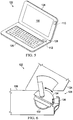
- FIG. 5 is a simplified schematic diagram illustrating a portion of an embodiment of an electronic device, in accordance with one embodiment of the present disclosure
- FIG. 6 is a simplified block diagram illustrating a portion of an embodiment of an electronic device, in accordance with one embodiment of the present disclosure
- FIG. 7 is a simplified block diagram illustrating a portion of an embodiment of an electronic device, in accordance with one embodiment of the present disclosure.
- FIG. 8 is a simplified a simplified flow diagram illustrating potential operations associated with one embodiment of the present disclosure.
- FIG. 10 is a simplified a simplified flow diagram illustrating potential operations associated with one embodiment of the present disclosure.
- FIG. 11 is a simplified a simplified flow diagram illustrating potential operations associated with one embodiment of the present disclosure.
- FIG. 12 is a simplified a simplified flow diagram illustrating potential operations associated with one embodiment of the present disclosure.
- FIG. 13 is a block diagram illustrating an example computing system that is arranged in a point-to-point configuration in accordance with an embodiment
- FIG. 14 is a simplified block diagram associated with an example ARM ecosystem system on chip (SOC) of the present disclosure.
- An electronic device in one example embodiment and includes a display and a bounce reduction mechanism configured to provide an active counterforce to a force on the display.
- a proximity sensor can detect when a device is going to create the force on the display. The active counterforce is provided if the force is greater than a threshold force.
- a screen bounce detection engine can detect oscillations of the display and the bounce reduction mechanism is configured to provide an active counterforce to dampen oscillation of the display.
- the bounce reduction mechanism is configured as a hinge.
- display 102 can be a touchscreen display that can detect the presence and location of a touch within a display area. For example, display 102 can detect when a user's hand (or some other input devices such as a stylus) reacts with display 102 .
- Electronic device 100 can include a battery and various electronics (e.g., processor, memory, etc.) to allow electronic device 100 to operate as a standalone tablet.
- Electronic device 100 may also include a wireless module, (e.g., Wi-Fi module, Bluetooth module, etc.) a camera, a microphone, and speakers.
- a wireless module e.g., Wi-Fi module, Bluetooth module, etc.
- a current technological trend is a touchscreen.
- screen bounce is a common user pain point on touch devices such as clamshells, detachable 2-in-1's, and docked tablets. This pain point has also become an ongoing issue with recent tablet design implementations for wireless charging using pedestal style kickstands.
- screen bounce occurs, it causes the user to lose focus on the display content and slows down and reduces precision of sequential user touch events.
- Most current known solutions rely on passive damping from the material which is not effective at quickly returning the display to equilibrium.
- chassis reduce in thickness, it can be increasingly difficult to provide enough structure for passive damping to react and dampen touch screen bounce from user touch input. What is needed is a system and method that reduces screen bounce and hinge slip by sensing incoming user touch dynamics and proactively engaging a reaction force from an active control mechanism to reduce the displacement of the touchscreen after a touch event.
- Bounce reduction engine 112 can be configured to utilizes input from a sensor array such as 3D cameras, proximity detection, and accelerometers (e.g., screen proximity sensor 108 , screen bound detection engine 110 , etc.) in conjunction with an active control drive to reduce bounce settling time and minimize peak displacement after a touch event.
- a sensor array such as 3D cameras, proximity detection, and accelerometers (e.g., screen proximity sensor 108 , screen bound detection engine 110 , etc.) in conjunction with an active control drive to reduce bounce settling time and minimize peak displacement after a touch event.
- Bounce reduction engine 112 can be configured to allow for adjustment and be active, strongly active, turned off, etc. depending on the power state of electronic device 100 and/or user preference. Bounce reduction engine 112 can also use sensor data already existing in current electronic devices to calculate phase and amplitude of anti-bounce force input. In addition, the system and method can scale with system torque requirements from small form factors to large all-in ones.
- screen proximity sensor 108 can be configured to input device motion towards display 102 .
- proximity sensor 108 can detect the incoming speed and predict impact time and magnitude based on acquired data and control logic which can be used in conjunction with passive control from acquired accelerometer data to mitigate screen bounce.
- predicted impact dynamics can be used to engage a proactive response of an active control system (e.g., bounce reduction engine 112 ) to reduce screen displacement and quickly dampen oscillations.
- FIG. 2 is a simplified block diagram of a portion of electronic device 100 in accordance with one embodiment of the present disclosure.
- electronic device 100 can include four display regions 1001 - 110 d .
- Each region of display 102 can include a screen bounce detection engine designed for the region.
- display region 114 a may be located in an upper left area of display device and can include screen bounce detection engine 110 a
- display region 114 b may be located in an upper right area of display device and can include screen bounce detection engine 110 b
- display region 114 c may be located in an lower left area of display device and can include screen bounce detection engine 110 c
- display region 114 d may be located in an lower right area of display device and can include screen bounce detection engine 110 d
- a screen bounce detection engine may be located in each region because the screen bounce in display region 114 a can be very different from the screen bounce in display region 114 d . By including a screen bounce detection engine in each region, an accurate assessment of screen bounce in each region can be determined.
- FIG. 3 is a simplified block diagram of a docking station 116 in accordance with one embodiment of the present disclosure.
- Docking station 116 can include bounce reduction mechanism 106 , one or more bounce detection engines 110 e and 110 f , bounce reduction engine 112 , a device support 118 , interconnect 120 , and base 144 .
- Interconnect 120 can be configured to couple an electronic device (e.g., electronic device 100 ) to docking station 116 can help facilitate communications between the electronic device and docking station 116 .
- Each bounce detection engine 110 e and 110 f can be configured to detect bounce or oscillations of device support 118 .
- the interaction may cause the display and device support 118 to bounce.
- device support 118 and the display on the electronic device may experience bounce or oscillations.
- docking station 116 can be configured to allow for wireless charging.
- a pedestal kickstand can provide flexibility to adjust screen angle while wirelessly charging. However, this is more susceptible to screen bounce and ⁇ or hinge slip due to the long span between the hinge axis and top of the touch screen.
- Bounce reduction engine 112 can be configured to ensure a controlled system bounce response even for thin tablets with pedestal kickstands.
- FIG. 4 is a simplified block diagram of a portion of docking station 116 in accordance with one embodiment of the present disclosure.
- bounce reduction mechanism 106 can include a linear actuator 138 and a piston 140 .
- bounce reduction mechanism 106 can be part of a pedestal kickstand style. Bounce reduction mechanism 106 can provide active resistance by using variable friction to absorb a desired amount of friction and reduce bouncing or oscillations of a touchscreen. Bounce reduction mechanism 106 can be configured to not provide too much resistance and create a bounce back or amply the bouncing of the touch screen.
- FIG. 5 is a simplified block diagram of a clamshell electronic device 122 in accordance with one embodiment of the present disclosure.
- Clamshell electronic device 122 can include a first housing 124 and a second housing 126 .
- First housing 124 can include a bounce detection engine 110 and touchscreen display 130 .
- Second housing 126 can include bounce reduction engine 112 .
- bounce reduction engine 112 can be located in first housing 124 .
- First housing 124 can be coupled to second housing 126 using hinge 128 .
- Hinge 128 can be configured with active elements to reduce bounce or oscillations of first housing 124 .
- hinge 128 can include a continuous hinge design.
- hinge 128 can include a continuous membrane of artificial muscle that attaches first housing 124 to second housing 126 and provides a sleek monolithic look.
- the continuous membrane can include EAP cells and may be controlled electrostatically by bounce reduction engine 112 .
- a simple voltage controller can control the voltage to the membrane causing it to expand and contract to provide the needed motion. When the voltage is increased the membrane contracts in one direction and expands in the other. By applying membrane segments independent of another it is possible to have expansion and contracting membranes coupled together which cause the bending of polymer film.
- first housing 124 can be rotated away from second housing 126 , (e.g., opened and closed) using voice command or touch or activation of a button.
- the open close position can be set to a predetermined position or adjusted infinitely automatically. Once open, the position or angle of first housing 124 can be adjusted by hand.
- the EAP has the ability to sense load by sensing change in capacitance. As a load is applied, the capacitance of the EAP cell changes. Based on load and duration, it can be relatively easy to detect the load is intentional and to allow the position of the display to adjust and then maintain position.
- inputs to touchscreen 130 can cause a “bounce” in first housing 124 that will change the capacitance. As this change in capacitance is detected it is translated into movement of touchscreen 130 .
- Bounce reduction engine 112 can be configured to respond with input to dampen the motion and quickly reduce the display bounce and return the display to a nominal position.
- FIG. 6 is a simplified block diagram of a portion of clamshell electronic device 122 in accordance with one embodiment of the present disclosure.
- hinge 128 can include a rotation drive configured as an active control drive to reduce bounce or oscillations of first housing 124 .
- a piezo motor 136 can vibrate using a wave signal to generate torque on a hinge shaft 134 through a friction surface. The increase in torque affects the rotation of hinge shaft 134 on rotation member 132 and can dampen oscillations or bouncing of first housing 124 .
- FIG. 7 is a simplified block diagram of a portion of a hinge in accordance with one embodiment of the present disclosure.
- the hinge can include an oscillating piezoceramic actuator 150 , a coupling element 144 , and a runner 146 .
- a bounce reduction engine can activate oscillating piezoceramic actuator 150 which would activate oscillating arm 148 and allowing 146 to walk or move in a desired direction and dampen the bounce or oscillations of a touchscreen. While various methods and means are illustrated for dampening the bounce or oscillations of a touchscreen, other methods and means may be used such as compact solenoids or artificial muscles and all are within the scope of this application.
- FIG. 8 is an example flowchart illustrating possible operations of a flow 800 that may be associated with the reduction of touchscreen bounce, in accordance with an embodiment.
- one or more operations of flow 800 may be performed by bounce detection engine 110 and bounce reduction engine 112 .
- input device motion towards a display is detect.
- screen proximity sensor 108 may detect the motion of user's hand 142 as it approaches display 102 .
- an incoming velocity towards the display is calculated.
- the system determines if the incoming velocity is greater than a threshold. If the incoming velocity is greater than a threshold, a counter force is applied to the display, as in 808 .
- bounce reduction engine 112 may determine that the incoming velocity of user's hand 142 is greater than a threshold and therefore cause bounce reduction mechanism 106 to apply a counter force.
- FIG. 9 is an example flowchart illustrating possible operations of a flow 900 that may be associated with the reduction of touchscreen bounce, in accordance with an embodiment.
- one or more operations of flow 900 may be performed by bounce detection engine 110 and bounce reduction engine 112 .
- movement of an input device towards a display is detected.
- screen proximity sensor 108 may detect the motion of user's hand 142 as it approaches display 102 .
- an area of the display where the input device will contact the display is determined. For example, it may be determined if the input device will contact display region 114 a , 114 b , 114 c , or 114 d .
- a velocity of the input device is determined.
- the system determines if the velocity of the input device is greater than a threshold for the determined area of the display where the input device will contact the display. If the the velocity of the input device is greater than a threshold for the determined area of the display where the input device will contact the display, then a counter-force is applied to the display at the approximate time that the input device will contact the display.
- a counter-force is applied to the display at the approximate time that the input device will contact the display.
- a counter-force is applied to the display at the approximate time that the input device will contact the display.
- FIG. 10 is an example flowchart illustrating possible operations of a flow 1000 that may be associated with the reduction of touchscreen bounce, in accordance with an embodiment.
- one or more operations of flow 1000 may be performed by bounce detection engine 110 and bounce reduction engine 112 .
- oscillation of an electronic device is detected.
- the system determines if the oscillation is greater than a threshold. If the oscillations is greater than a threshold, then a counter force is applied to the electronic device to dampen the oscillation, as in 1006 .
- some type of active element such as bounce reduction mechanism 106 , hinge shaft 134 , or some other active element that can be activated to produce the counter force may be applied.
- the system again determines if the oscillation is greater than a threshold. If the oscillation is not greater than a threshold, the process ends and a counter force is not applied.
- FIG. 11 is an example flowchart illustrating possible operations of a flow 1100 that may be associated with the reduction of touchscreen bounce, in accordance with an embodiment.
- one or more operations of flow 1100 may be performed by bounce detection engine 110 and bounce reduction engine 112 .
- a default position of a display is determined.
- the system determines if the display is in the default position. If the system is not in the default position, then a force is applied to return the display to the default position, as in 1106 . For example, some type of active element such as bounce reduction mechanism 106 , hinge shaft 134 , or some other active element that can be activated to produce the counter force may be applied. Then, the system returns to 1104 and determines if the display is in the default position. In an illustrative example, if a user is continuously pushing on the display, the system may determine that a counter force needs to be applied.
- FIG. 12 is an example flowchart illustrating possible operations of a flow 1200 that may be associated with the reduction of touchscreen bounce, in accordance with an embodiment.
- one or more operations of flow 1200 may be performed by bounce detection engine 110 and bounce reduction engine 112 .
- a force that causes a displacement of a display is detected.
- the system determines if the displacement of the display is greater than a threshold value. If the displacement is greater than a threshold value, then a counter force is applied to the display, as in 1206 and the system again determines if the displacement of the display is greater than a threshold value, as in 1204 .
- FIG. 13 illustrates a computing system 1300 that is arranged in a point-to-point (PtP) configuration according to an embodiment.
- FIG. 13 shows a system where processors, memory, and input/output devices are interconnected by a number of point-to-point interfaces.
- processors, memory, and input/output devices are interconnected by a number of point-to-point interfaces.
- one or more of the network elements of communication system 100 may be configured in the same or similar manner as computing system 1300 .
- system 1300 may include several processors, of which only two, processors 1370 and 1380 , are shown for clarity. While two processors 1370 and 1380 are shown, it is to be understood that an embodiment of system 1300 may also include only one such processor.
- Processors 1370 and 1380 may each include a set of cores (i.e., processor cores 1374 A and 1374 B and processor cores 1384 A and 1384 B) to execute multiple threads of a program. The cores may be configured to execute instruction code in a manner similar to that discussed above with reference to FIGS. 1-12 .
- Each processor 1370 , 1380 may include at least one shared cache 1371 , 1381 . Shared caches 1371 , 1381 may store data (e.g., instructions) that are utilized by one or more components of processors 1370 , 1380 , such as processor cores 1374 and 1384 .
- Processors 1370 and 1380 may also each include integrated memory controller logic (MC) 1372 and 1382 to communicate with memory elements 1332 and 1334 .
- Memory elements 1332 and/or 1334 may store various data used by processors 1370 and 1380 .
- memory controller logic 1372 and 1382 may be discrete logic separate from processors 1370 and 1380 .
- Processors 1370 and 1380 may be any type of processor and may exchange data via a point-to-point (PtP) interface 1350 using point-to-point interface circuits 1378 and 1388 , respectively.
- Processors 1370 and 1380 may each exchange data with a chipset 1390 via individual point-to-point interfaces 1352 and 1354 using point-to-point interface circuits 1376 , 1386 , 1394 , and 1398 .
- Chipset 1390 may also exchange data with a high-performance graphics circuit 1338 via a high-performance graphics interface 1339 , using an interface circuit 1392 , which could be a PtP interface circuit.
- any or all of the PtP links illustrated in FIG. 13 could be implemented as a multi-drop bus rather than a PtP link.
- Chipset 1390 may be in communication with a bus 1320 via an interface circuit 1396 .
- Bus 1320 may have one or more devices that communicate over it, such as a bus bridge 1318 and I/O devices 1316 .
- bus bridge 1318 may be in communication with other devices such as a keyboard/mouse 1312 (or other input devices such as a touch screen, trackball, etc.), communication devices 1326 (such as modems, network interface devices, or other types of communication devices that may communicate through a computer network 1360 ), audio I/O devices 1314 , and/or a data storage device 1328 .
- Data storage device 1328 may store code 1330 , which may be executed by processors 1370 and/or 1380 .
- any portions of the bus architectures could be implemented with one or more PtP links.
- the computer system depicted in FIG. 13 is a schematic illustration of an embodiment of a computing system that may be utilized to implement various embodiments discussed herein. It will be appreciated that various components of the system depicted in FIG. 13 may be combined in a system-on-a-chip (SoC) architecture or in any other suitable configuration. For example, embodiments disclosed herein can be incorporated into systems including mobile devices such as smart cellular telephones, tablet computers, personal digital assistants, portable gaming devices, etc. It will be appreciated that these mobile devices may be provided with SoC architectures in at least some embodiments.
- SoC system-on-a-chip
- FIG. 14 is a simplified block diagram associated with an example ARM ecosystem SOC 1400 of the present disclosure.
- At least one example implementation of the present disclosure can include the reduction of touchscreen bounce features discussed herein and an ARM component.
- the example of FIG. 14 can be associated with any ARM core (e.g., A-9, A-15, etc.).
- the architecture can be part of any type of tablet, smartphone (inclusive of AndroidTM phones, iPhonesTM), iPadTM, Google NexusTM, Microsoft SurfaceTM, personal computer, server, video processing components, laptop computer (inclusive of any type of notebook), UltrabookTM system, any type of touch-enabled input device, etc.
- ARM ecosystem SOC 1400 may include multiple cores 1406 - 1407 , an L2 cache control 1408 , a bus interface unit 1409 , an L2 cache 1410 , a graphics processing unit (GPU) 1415 , an interconnect 1402 , a video codec 1420 , and a liquid crystal display (LCD) I/F 1425 , which may be associated with mobile industry processor interface (MIPI)/high-definition multimedia interface (HDMI) links that couple to an LCD.
- MIPI mobile industry processor interface
- HDMI high-definition multimedia interface
- ARM ecosystem SOC 1400 may also include a subscriber identity module (SIM) I/F 1430 , a boot read-only memory (ROM) 1435 , a synchronous dynamic random access memory (SDRAM) controller 1440 , a flash controller 1445 , a serial peripheral interface (SPI) master 1450 , a suitable power control 1455 , a dynamic RAM (DRAM) 1460 , and flash 1465 .
- SIM subscriber identity module
- ROM read-only memory
- SDRAM synchronous dynamic random access memory
- SPI serial peripheral interface
- suitable power control 1455 a dynamic RAM (DRAM) 1460
- flash 1465 flash 1465
- one or more example embodiments include one or more communication capabilities, interfaces, and features such as instances of BluetoothTM 1470 , a 3G modem 1475 , a global positioning system (GPS) 1480 , and an 802.11 Wi-Fi 1485 .
- GPS global positioning system
- the example of FIG. 14 can offer processing capabilities, along with relatively low power consumption to enable computing of various types (e.g., mobile computing, high-end digital home, servers, wireless infrastructure, etc.).
- such an architecture can enable any number of software applications (e.g., AndroidTM, Adobe® Flash® Player, Java Platform Standard Edition (Java SE), JavaFX, Linux, Microsoft Windows Embedded, Symbian and Ubuntu, etc.).
- the core processor may implement an out-of-order superscalar pipeline with a coupled low-latency level-2 cache.
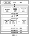
- FIG. 15 illustrates a processor core 1500 according to an embodiment.
- Processor core 1500 may be the core for any type of processor, such as a micro-processor, an embedded processor, a digital signal processor (DSP), a network processor, or other device to execute code.
- DSP digital signal processor
- FIG. 15 a processor may alternatively include more than one of the processor core 1500 illustrated in FIG. 15 .
- processor core 1500 represents one example embodiment of processors cores 1374 a , 1374 b , 1374 a , and 1374 b shown and described with reference to processors 1370 and 1380 of FIG. 13 .
- Processor core 1500 may be a single-threaded core or, for at least one embodiment, processor core 1500 may be multithreaded in that it may include more than one hardware thread context (or “logical processor”) per core.
- FIG. 15 also illustrates a memory 1502 coupled to processor core 1500 in accordance with an embodiment.
- Memory 1502 may be any of a wide variety of memories (including various layers of memory hierarchy) as are known or otherwise available to those of skill in the art.
- Memory 1502 may include code 1504 , which may be one or more instructions, to be executed by processor core 1500 .
- Processor core 1500 can follow a program sequence of instructions indicated by code 1504 .
- Each instruction enters a front-end logic 1506 and is processed by one or more decoders 1508 .
- the decoder may generate, as its output, a micro operation such as a fixed width micro operation in a predefined format, or may generate other instructions, microinstructions, or control signals that reflect the original code instruction.
- Front-end logic 1506 also includes register renaming logic 1510 and scheduling logic 1512 , which generally allocate resources and queue the operation corresponding to the instruction for execution.
- Processor core 1500 can also include execution logic 1514 having a set of execution units 1516 - 1 through 1516 -N. Some embodiments may include a number of execution units dedicated to specific functions or sets of functions. Other embodiments may include only one execution unit or one execution unit that can perform a particular function. Execution logic 1514 performs the operations specified by code instructions.
- back-end logic 1518 can retire the instructions of code 1504 .
- processor core 1500 allows out of order execution but requires in order retirement of instructions.
- Retirement logic 1520 may take a variety of known forms (e.g., re-order buffers or the like). In this manner, processor core 1500 is transformed during execution of code 1504 , at least in terms of the output generated by the decoder, hardware registers and tables utilized by register renaming logic 1510 , and any registers (not shown) modified by execution logic 1514 .
- a processor may include other elements on a chip with processor core 1500 , at least some of which were shown and described herein with reference to FIG. 13 .
- a processor may include memory control logic along with processor core 1500 .
- the processor may include I/O control logic and/or may include I/O control logic integrated with memory control logic.
- FIGS. 8-12 illustrate only some of the possible correlating scenarios and patterns that may be executed by, or within, communication system 100 . Some of these operations may be deleted or removed where appropriate, or these operations may be modified or changed considerably without departing from the scope of the present disclosure. In addition, a number of these operations have been described as being executed concurrently with, or in parallel to, one or more additional operations. However, the timing of these operations may be altered considerably.
- the preceding operational flows have been offered for purposes of example and discussion. Substantial flexibility is provided by communication system 100 in that any suitable arrangements, chronologies, configurations, and timing mechanisms may be provided without departing from the teachings of the present disclosure.
- Example A1 is an electronic device that includes a display and a bounce reduction mechanism configured to provide an active counterforce to a force on the display.
- Example A2 the subject matter of Example A1 may optionally include a proximity sensor, wherein the proximity sensor can detect when a device is going to create the force on the display.
- Example A3 the subject matter of any of the preceding ‘A’ Examples can optionally include where the active counterforce is provided if the force is greater than a threshold force.
- Example A4 the subject matter of any of the preceding ‘A’ Examples can optionally include a screen bounce detection engine to detect oscillations of the display.
- Example A5 the subject matter of any of the preceding ‘A’ Examples can optionally include where the bounce reduction mechanism is configured to provide an active counterforce to dampen oscillation of the display.
- Example A6 the subject matter of any of the preceding ‘A’ Examples can optionally include where the bounce reduction mechanism is configured as a hinge.
- Example A7 the subject matter of any of the preceding ‘A’ Examples can optionally include where the bounce reduction mechanism is a oscillating piezoceramic actuator.
- Example M1 is a method that includes detecting a force on a display and providing an active counter force to counter the force on the display.
- Example M2 the subject matter of any of the preceding ‘M’ Examples can optionally include detecting when a device is going to create the force on the display.
- Example M3 the subject matter of any of the preceding ‘M’ Examples can optionally include where the active counterforce is provided if the force is greater than a threshold force.
- Example M4 the subject matter of any of the preceding ‘M’ Examples can optionally include detecting oscillations of the display.
- Example M5 the subject matter of any of the preceding ‘M’ Examples can optionally include where the bounce reduction mechanism is configured to provide an active counterforce to dampen oscillation of the display.
- Example M6 the subject matter of any of the preceding ‘M’ Examples can optionally include where the bounce reduction mechanism is configured as a hinge.
- Example AA1 can include an electronic device that includes a touchscreen display, a bounce reduction engine configured to calculate a counterforce to a force on the touchscreen display, and a bounce reduction mechanism configured to provide the active counterforce to the force on the touchscreen display.
- Example AA2 the subject matter of any of the preceding ‘AA’ Examples can optionally include a proximity sensor, wherein the proximity sensor can detect when a device is going to create the force on the display.
- Example AA3 the subject matter of any of the preceding ‘AA’ Examples can optionally include where the active counterforce is provided if the force is greater than a threshold force.
- Example AA4 the subject matter of any of the preceding ‘AA’ Examples can optionally include a screen bounce detection engine to detect oscillations of the display.
- Example AA4 the subject matter of any of the preceding ‘AA’ Examples can optionally include where the bounce reduction mechanism is configured as a hinge.
- An example system S1 can include means for detecting a force on a display and means for providing an active counter force to counter the force on the display.
- Example S3 the subject matter of any of the preceding ‘S’ Examples can optionally means for detecting oscillations of the display.
- Example S4 the subject matter of any of the preceding ‘S’ Examples can optionally include where the bounce reduction mechanism is configured to provide an active counterforce to dampen oscillation of the display.
- Example X1 is a machine-readable storage medium including machine-readable instructions to implement a method or realize an apparatus as in any one of the Examples A1-A7, M1-M7, and AA1-AA4.
- Example Y1 is an apparatus comprising means for performing of any of the Example methods M1-M7.
- the subject matter of Example Y1 can optionally include the means for performing the method comprising a processor and a memory.
- Example Y3 the subject matter of Example Y2 can optionally include the memory comprising machine-readable instructions.
Landscapes
- Engineering & Computer Science (AREA)
- Theoretical Computer Science (AREA)
- Computer Hardware Design (AREA)
- General Engineering & Computer Science (AREA)
- Physics & Mathematics (AREA)
- Human Computer Interaction (AREA)
- General Physics & Mathematics (AREA)
- Mathematical Physics (AREA)
- User Interface Of Digital Computer (AREA)
- Controls And Circuits For Display Device (AREA)
Abstract
Description
Claims (14)
Applications Claiming Priority (1)
| Application Number | Priority Date | Filing Date | Title |
|---|---|---|---|
| PCT/US2015/067232 WO2017111928A1 (en) | 2015-12-22 | 2015-12-22 | Reduction of touchscreen bounce |
Publications (2)
| Publication Number | Publication Date |
|---|---|
| US20180348941A1 US20180348941A1 (en) | 2018-12-06 |
| US10698518B2 true US10698518B2 (en) | 2020-06-30 |
Family
ID=59091009
Family Applications (1)
| Application Number | Title | Priority Date | Filing Date |
|---|---|---|---|
| US15/778,755 Active US10698518B2 (en) | 2015-12-22 | 2015-12-22 | Reduction of touchscreen bounce |
Country Status (2)
| Country | Link |
|---|---|
| US (1) | US10698518B2 (en) |
| WO (1) | WO2017111928A1 (en) |
Families Citing this family (1)
| Publication number | Priority date | Publication date | Assignee | Title |
|---|---|---|---|---|
| US10698518B2 (en) | 2015-12-22 | 2020-06-30 | Intel Corporation | Reduction of touchscreen bounce |
Citations (19)
| Publication number | Priority date | Publication date | Assignee | Title |
|---|---|---|---|---|
| US20050109914A1 (en) * | 2003-10-24 | 2005-05-26 | Ryaboy Vyacheslav M. | Instrumented platform for vibration-sensitive equipment |
| US20070024593A1 (en) * | 2005-07-28 | 2007-02-01 | Schroeder Dale W | Touch device and method for providing tactile feedback |
| US20080051942A1 (en) | 2004-07-29 | 2008-02-28 | Anorad Corporation | Damping and stabilization for linear motor stage |
| US20110051334A1 (en) * | 2008-03-14 | 2011-03-03 | David Griffith | Suspension for a pressure sensitive touch display or panel |
| US20120050176A1 (en) * | 2010-08-30 | 2012-03-01 | Apple Inc. | Accelerometer determined input velocity |
| US8269732B2 (en) * | 2008-02-29 | 2012-09-18 | Lg Electronics Inc. | Portable terminal |
| US20120249474A1 (en) | 2011-04-01 | 2012-10-04 | Analog Devices, Inc. | Proximity and force detection for haptic effect generation |
| US20130300255A1 (en) * | 2012-05-08 | 2013-11-14 | Samsung Electro-Mechanics Co., Ltd. | Piezoelectric vibration module |
| US20140098474A1 (en) * | 2011-12-28 | 2014-04-10 | Achintya K. Bhowmik | Locking hinge assembly for electronic device |
| US20140336820A1 (en) * | 2012-11-22 | 2014-11-13 | Panasonic Corporation | Arm control apparatus, arm control method, arm control program, robot, and integrated electronic circuit for arm control |
| US20140343729A1 (en) * | 2012-11-22 | 2014-11-20 | Panasonic Corporation | Arm control apparatus, arm control method, arm control program, robot, and integrated electronic circuit for arm control |
| US20150000083A1 (en) * | 2013-06-28 | 2015-01-01 | Paul J. Gwin | Hinge assembly |
| US20150036273A1 (en) | 2013-07-30 | 2015-02-05 | Michael Hui | Stacking detachable tablet |
| US20150036289A1 (en) | 2013-08-05 | 2015-02-05 | Dell Products L.P. | Method for Eliminating Tilting of Laptop Devices |
| US20150138713A1 (en) * | 2013-11-20 | 2015-05-21 | Fujitsu Limited | Hinge device and electronic device equipped with hinge device |
| US20160139747A1 (en) * | 2010-12-20 | 2016-05-19 | Apple Inc. | Device, method, and graphical user interface for navigation of concurrently open software applications |
| US20170044810A1 (en) * | 2015-08-13 | 2017-02-16 | Apple Inc. | Variable resistance electronic device brake clutch |
| US20170045109A1 (en) * | 2014-04-25 | 2017-02-16 | Hitachi, Ltd. | Active damping device and design method |
| WO2017111928A1 (en) | 2015-12-22 | 2017-06-29 | Intel Corporation | Reduction of touchscreen bounce |
-
2015
- 2015-12-22 US US15/778,755 patent/US10698518B2/en active Active
- 2015-12-22 WO PCT/US2015/067232 patent/WO2017111928A1/en not_active Ceased
Patent Citations (31)
| Publication number | Priority date | Publication date | Assignee | Title |
|---|---|---|---|---|
| US7320455B2 (en) * | 2003-10-24 | 2008-01-22 | Newport Corporation | Instrumented platform for vibration-sensitive equipment |
| US20050109914A1 (en) * | 2003-10-24 | 2005-05-26 | Ryaboy Vyacheslav M. | Instrumented platform for vibration-sensitive equipment |
| US20080051942A1 (en) | 2004-07-29 | 2008-02-28 | Anorad Corporation | Damping and stabilization for linear motor stage |
| US8269738B2 (en) * | 2005-07-28 | 2012-09-18 | Pixart Imaging Inc. | Touch device and method for providing tactile feedback |
| US20070024593A1 (en) * | 2005-07-28 | 2007-02-01 | Schroeder Dale W | Touch device and method for providing tactile feedback |
| US7616192B2 (en) * | 2005-07-28 | 2009-11-10 | Avago Technologies Ecbu Ip (Singapore) Pte. Ltd. | Touch device and method for providing tactile feedback |
| US20100039403A1 (en) * | 2005-07-28 | 2010-02-18 | Avago Technologies Ecbu Ip (Singapore) Pte. Ltd. | Touch device and method for providing tactile feedback |
| US8269732B2 (en) * | 2008-02-29 | 2012-09-18 | Lg Electronics Inc. | Portable terminal |
| US20110051334A1 (en) * | 2008-03-14 | 2011-03-03 | David Griffith | Suspension for a pressure sensitive touch display or panel |
| US8270148B2 (en) * | 2008-03-14 | 2012-09-18 | David Griffith | Suspension for a pressure sensitive touch display or panel |
| US8884888B2 (en) * | 2010-08-30 | 2014-11-11 | Apple Inc. | Accelerometer determined input velocity |
| US20120050176A1 (en) * | 2010-08-30 | 2012-03-01 | Apple Inc. | Accelerometer determined input velocity |
| US10007400B2 (en) * | 2010-12-20 | 2018-06-26 | Apple Inc. | Device, method, and graphical user interface for navigation of concurrently open software applications |
| US20160139747A1 (en) * | 2010-12-20 | 2016-05-19 | Apple Inc. | Device, method, and graphical user interface for navigation of concurrently open software applications |
| US20120249474A1 (en) | 2011-04-01 | 2012-10-04 | Analog Devices, Inc. | Proximity and force detection for haptic effect generation |
| US20140098474A1 (en) * | 2011-12-28 | 2014-04-10 | Achintya K. Bhowmik | Locking hinge assembly for electronic device |
| US20130300255A1 (en) * | 2012-05-08 | 2013-11-14 | Samsung Electro-Mechanics Co., Ltd. | Piezoelectric vibration module |
| US8928204B2 (en) * | 2012-05-08 | 2015-01-06 | Samsung Electro-Mechanics Co., Ltd. | Piezoelectric vibration module |
| US9102057B2 (en) * | 2012-11-22 | 2015-08-11 | Panasonic Intellectual Property Management Co., Ltd. | Arm control apparatus, arm control method, arm control program, robot, and integrated electronic circuit for arm control |
| US20140336820A1 (en) * | 2012-11-22 | 2014-11-13 | Panasonic Corporation | Arm control apparatus, arm control method, arm control program, robot, and integrated electronic circuit for arm control |
| US20140343729A1 (en) * | 2012-11-22 | 2014-11-20 | Panasonic Corporation | Arm control apparatus, arm control method, arm control program, robot, and integrated electronic circuit for arm control |
| US9114531B2 (en) * | 2012-11-22 | 2015-08-25 | Panasonic Intellectual Property Management Co., Ltd. | Arm control apparatus, arm control method, arm control program, robot, and integrated electronic circuit for arm control |
| US20150000083A1 (en) * | 2013-06-28 | 2015-01-01 | Paul J. Gwin | Hinge assembly |
| US20150036273A1 (en) | 2013-07-30 | 2015-02-05 | Michael Hui | Stacking detachable tablet |
| US20150036289A1 (en) | 2013-08-05 | 2015-02-05 | Dell Products L.P. | Method for Eliminating Tilting of Laptop Devices |
| US20150138713A1 (en) * | 2013-11-20 | 2015-05-21 | Fujitsu Limited | Hinge device and electronic device equipped with hinge device |
| US9612626B2 (en) * | 2013-11-20 | 2017-04-04 | Fujitsu Limited | Hinge device and electronic device equipped with hinge device |
| US20170045109A1 (en) * | 2014-04-25 | 2017-02-16 | Hitachi, Ltd. | Active damping device and design method |
| US10107355B2 (en) * | 2014-04-25 | 2018-10-23 | Hitachi Ltd. | Active damping device and design method |
| US20170044810A1 (en) * | 2015-08-13 | 2017-02-16 | Apple Inc. | Variable resistance electronic device brake clutch |
| WO2017111928A1 (en) | 2015-12-22 | 2017-06-29 | Intel Corporation | Reduction of touchscreen bounce |
Non-Patent Citations (1)
| Title |
|---|
| International Search Report and Written Opinion issued in PCT Application No. PCT/US2015/067232 dated Aug. 24, 2016; 12 pages. |
Also Published As
| Publication number | Publication date |
|---|---|
| US20180348941A1 (en) | 2018-12-06 |
| WO2017111928A1 (en) | 2017-06-29 |
Similar Documents
| Publication | Publication Date | Title |
|---|---|---|
| JP6363205B2 (en) | Mechanism to avoid unintended user interaction with convertible mobile device during conversion | |
| US10175806B2 (en) | Touchscreen for use with flexible display | |
| US9557778B2 (en) | Hinge for a device | |
| US20180246546A1 (en) | Hinge for an electronic device | |
| US10373364B2 (en) | Termination of animation | |
| US20140092003A1 (en) | Direct haptic feedback | |
| US11861076B1 (en) | System and method for obtaining user input with magnetic sensing | |
| WO2014209409A1 (en) | Foldable configurations for a thumb typing keyboard | |
| KR20190003515A (en) | 360 degree hinge assembly for electronic devices | |
| WO2019245634A1 (en) | System, apparatus and method for responsive autonomous hardware performance state control of a processor | |
| WO2014209383A1 (en) | Hinge assembly | |
| US10698518B2 (en) | Reduction of touchscreen bounce | |
| US10402413B2 (en) | Hardware accelerator for selecting data elements | |
| WO2018063751A1 (en) | Compensation control for variable power rails | |
| US10416692B2 (en) | Method and apparatus for reducing capacitor-induced noise | |
| US20140009398A1 (en) | Portable computer with a twistable display | |
| US20220308676A1 (en) | Rotation-based actions on computing devices |
Legal Events
| Date | Code | Title | Description |
|---|---|---|---|
| AS | Assignment |
Owner name: INTEL CORPORATION, CALIFORNIA Free format text: ASSIGNMENT OF ASSIGNORS INTEREST;ASSIGNORS:ARIK, KENAN HUSEYIN;SPRENGER, MARK E.;MAGI, ALEKSANDER;AND OTHERS;SIGNING DATES FROM 20160105 TO 20160112;REEL/FRAME:045894/0677 |
|
| FEPP | Fee payment procedure |
Free format text: ENTITY STATUS SET TO UNDISCOUNTED (ORIGINAL EVENT CODE: BIG.); ENTITY STATUS OF PATENT OWNER: LARGE ENTITY |
|
| STPP | Information on status: patent application and granting procedure in general |
Free format text: DOCKETED NEW CASE - READY FOR EXAMINATION |
|
| STPP | Information on status: patent application and granting procedure in general |
Free format text: NON FINAL ACTION MAILED |
|
| STPP | Information on status: patent application and granting procedure in general |
Free format text: RESPONSE TO NON-FINAL OFFICE ACTION ENTERED AND FORWARDED TO EXAMINER |
|
| STPP | Information on status: patent application and granting procedure in general |
Free format text: FINAL REJECTION MAILED |
|
| STPP | Information on status: patent application and granting procedure in general |
Free format text: RESPONSE AFTER FINAL ACTION FORWARDED TO EXAMINER |
|
| STCF | Information on status: patent grant |
Free format text: PATENTED CASE |
|
| CC | Certificate of correction | ||
| MAFP | Maintenance fee payment |
Free format text: PAYMENT OF MAINTENANCE FEE, 4TH YEAR, LARGE ENTITY (ORIGINAL EVENT CODE: M1551); ENTITY STATUS OF PATENT OWNER: LARGE ENTITY Year of fee payment: 4 |