US10698501B2 - Systems and methods for three dimensional control of mobile applications - Google Patents
Systems and methods for three dimensional control of mobile applications Download PDFInfo
- Publication number
- US10698501B2 US10698501B2 US15/200,880 US201615200880A US10698501B2 US 10698501 B2 US10698501 B2 US 10698501B2 US 201615200880 A US201615200880 A US 201615200880A US 10698501 B2 US10698501 B2 US 10698501B2
- Authority
- US
- United States
- Prior art keywords
- imu
- orientation
- interrupt signals
- accelerometer
- magnetometer
- Prior art date
- Legal status (The legal status is an assumption and is not a legal conclusion. Google has not performed a legal analysis and makes no representation as to the accuracy of the status listed.)
- Active, expires
Links
Images


Classifications
-
- G—PHYSICS
- G06—COMPUTING OR CALCULATING; COUNTING
- G06F—ELECTRIC DIGITAL DATA PROCESSING
- G06F3/00—Input arrangements for transferring data to be processed into a form capable of being handled by the computer; Output arrangements for transferring data from processing unit to output unit, e.g. interface arrangements
- G06F3/01—Input arrangements or combined input and output arrangements for interaction between user and computer
- G06F3/03—Arrangements for converting the position or the displacement of a member into a coded form
- G06F3/033—Pointing devices displaced or positioned by the user, e.g. mice, trackballs, pens or joysticks; Accessories therefor
- G06F3/0346—Pointing devices displaced or positioned by the user, e.g. mice, trackballs, pens or joysticks; Accessories therefor with detection of the device orientation or free movement in a three-dimensional [3D] space, e.g. 3D mice, 6-DOF [six degrees of freedom] pointers using gyroscopes, accelerometers or tilt-sensors
-
- G—PHYSICS
- G06—COMPUTING OR CALCULATING; COUNTING
- G06F—ELECTRIC DIGITAL DATA PROCESSING
- G06F3/00—Input arrangements for transferring data to be processed into a form capable of being handled by the computer; Output arrangements for transferring data from processing unit to output unit, e.g. interface arrangements
- G06F3/01—Input arrangements or combined input and output arrangements for interaction between user and computer
- G06F3/017—Gesture based interaction, e.g. based on a set of recognized hand gestures
-
- G—PHYSICS
- G06—COMPUTING OR CALCULATING; COUNTING
- G06F—ELECTRIC DIGITAL DATA PROCESSING
- G06F3/00—Input arrangements for transferring data to be processed into a form capable of being handled by the computer; Output arrangements for transferring data from processing unit to output unit, e.g. interface arrangements
- G06F3/01—Input arrangements or combined input and output arrangements for interaction between user and computer
- G06F3/048—Interaction techniques based on graphical user interfaces [GUI]
- G06F3/0481—Interaction techniques based on graphical user interfaces [GUI] based on specific properties of the displayed interaction object or a metaphor-based environment, e.g. interaction with desktop elements like windows or icons, or assisted by a cursor's changing behaviour or appearance
- G06F3/04815—Interaction with a metaphor-based environment or interaction object displayed as three-dimensional [3D], e.g. changing the user viewpoint with respect to the environment or object
-
- G—PHYSICS
- G06—COMPUTING OR CALCULATING; COUNTING
- G06F—ELECTRIC DIGITAL DATA PROCESSING
- G06F2203/00—Indexing scheme relating to G06F3/00 - G06F3/048
- G06F2203/038—Indexing scheme relating to G06F3/038
- G06F2203/0382—Plural input, i.e. interface arrangements in which a plurality of input device of the same type are in communication with a PC
-
- G—PHYSICS
- G06—COMPUTING OR CALCULATING; COUNTING
- G06F—ELECTRIC DIGITAL DATA PROCESSING
- G06F3/00—Input arrangements for transferring data to be processed into a form capable of being handled by the computer; Output arrangements for transferring data from processing unit to output unit, e.g. interface arrangements
- G06F3/01—Input arrangements or combined input and output arrangements for interaction between user and computer
- G06F3/011—Arrangements for interaction with the human body, e.g. for user immersion in virtual reality
- G06F3/014—Hand-worn input/output arrangements, e.g. data gloves
Definitions
- the present specification generally relates to systems and method for providing input control to a mobile device.
- While some devices are available to provide motion based three dimensional input to console and personal computers (e.g., Nintendo's Wii, Microsoft's Kinect, Perception Neuron, and Leap Motion), such motion capture devices are not available for use with mobile devices.
- the aforementioned motion capture devices are relatively expensive as they rely upon complex sensing systems. Additionally, motion capture devices frequently require the use body suits or harnesses, which can diminish user experience. Moreover, even with the complexity of such motion capture devices, the motion capture devices frequently generate excessive amounts of sensor drift, i.e., the sensor erroneously detects motion when the user is stationary.
- a mobile device can include memory and a display communicatively coupled to one or more processors.
- the memory can store machine readable instructions.
- the one or more processors can execute the machine readable instructions to receive a combined orientation signal indicative of a first Inertial Measurement Unit (IMU) device and a second IMU device.
- IMU Inertial Measurement Unit
- a rendered object can be rendered within a scene upon the display based upon the combined orientation signal.
- the scene can include a scene object and an interaction object. The interaction object can be manipulated based upon the position of the rendered object within the scene and the combined orientation signal.
- a method for three dimensional control can include receiving a combined orientation signal indicative of a first IMU inertial measurement unit (IMU) device and a second IMU device with one or more processors of a mobile device.
- a rendered object can be rendered within a scene upon a display of the mobile device based upon the combined orientation signal.
- the scene can include a scene object and an interaction object.
- the display can be communicatively coupled to the one or more processors.
- the interaction object can be manipulated based upon the position of the rendered object within the scene and the combined orientation signal.
- a method for three dimensional control can include receiving a combined orientation signal indicative of a first inertial measurement unit (IMU) device and a second IMU device automatically with one or more processors of a mobile device.
- the mobile device can include a display communicatively coupled to the one or more processors.
- a rendered object can be rendered, automatically with the one or more processors, within a scene upon the display of the mobile device based upon the combined orientation signal.
- the scene can include a scene object that cannot be manipulated by the rendered object and a plurality of interaction objects.
- One or more object rays can be rendered, automatically with the one or more processors, within the scene upon the display of the mobile device.
- the one or more object rays can extend between a nearest object of the plurality of interaction objects to the rendered object and the rendered object.
- the interaction object can be manipulated, automatically with the one or more processors, based upon the position of the rendered object within the scene and the combined orientation signal.
- a method for three dimensional control can include receiving a combined orientation signal indicative of a first IMU device and a second IMU device automatically with one or more processors of a mobile device.
- the mobile device can include a display communicatively coupled to the one or more processors.
- a rendered object can be rendered, automatically with the one or more processors, within a scene upon a display of the mobile device based upon the combined orientation signal.
- the scene can include a scene object that cannot be manipulated by the rendered object and an interaction object.
- a reference ray can be rendered, automatically with the one or more processors, within the scene upon the display of the mobile device. The reference ray can extend between the scene object and the rendered object.
- the interaction object can be manipulated, automatically with the one or more processors, based upon the position of the rendered object within the scene and the combined orientation signal.
- the first IMU device, the second IMU device, or both can include an accelerometer, a gyroscope and a magnetometer.
- the first IMU device can include a low power mobile interface.
- the first IMU device can be communicatively coupled to the mobile device via the low power mobile interface.
- the low power mobile interface can be a Bluetooth low energy (BLE) transceiver.
- the first IMU device can transmit the combined orientation signal via the low power mobile interface.
- BLE Bluetooth low energy
- each of the first IMU device and the second IMU device can include low power communication hardware.
- the first IMU device and the second IMU device can be communicatively coupled via the low power communication hardware.
- the first IMU device can receive orientation signals from the second IMU device via the low power communication hardware.
- the orientation signals can be indicative of the orientation, acceleration or both of the second IMU device.
- the first IMU device can include an IMU processor that executes a fusion algorithm to generate the combined orientation signal based at least in part upon the orientation signals of the second IMU device.
- the second IMU device can be a node IMU device configured to be attached at a forearm region of the user.
- the node IMU device can include an IMU sensor that is communicatively coupled to the IMU processor and configured to detect orientation information.
- the IMU sensor can include an accelerometer, a gyroscope and a magnetometer.
- the master IMU device can include a low power communication hardware configured to receive and transmit data signals.
- the low power communication hardware can include an ANT wireless module.
- the rendered object can include two elongate members that are connected at a common location.
- each of the elongate members can move with the same degree of freedom as the node IMU device and the master IMU device.
- one or more reference rays can be rendered upon the display of the mobile device.
- the reference rays can be configured to provide visual feedback indicative of the relative positioning between the rendered object and a scene object.
- the scene object can serve as a datum within the scene.
- each of the reference rays can project from the datum location to a position upon the rendered object.
- the scene object can include a horizontal surface.
- touch input of the display can receive user tactile input to control movement of the rendered object relative to the scene.
- the second IMU device can be located at a forearm region of the arm of the user
- the third IMU device can be located at a biceps region of a second arm
- the fourth IMU device can be located at a forearm region of the second arm.
- FIG. 1 schematically depicts a three dimensional control system according to one or more embodiments shown and described herein;
- FIG. 2 schematically depicts the mobile device of the system of FIG. 1 according to one or more embodiments shown and described herein;
- FIG. 3 schematically depicts the master IMU device of the system of FIG. 1 according to one or more embodiments shown and described herein;
- FIG. 4 graphically depicts timing of an event flow according to one or more embodiments shown and described herein;
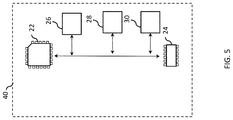
- FIG. 5 schematically depicts the node IMU device of the system of FIG. 1 according to one or more embodiments shown and described herein;
- FIGS. 6 and 7 schematically depict a three dimensional control system according to one or more embodiments shown and described herein;
- FIG. 8 schematically depicts a three dimensional control system according to one or more embodiments shown and described herein;
- FIG. 9 schematically depicts a method for providing three dimensional control according to one or more embodiments shown and described herein.
- FIG. 10 schematically depicts a scene rendered upon a display of a mobile device according to one or more embodiments shown and described herein;
- FIG. 11 schematically depicts results of drift testing according to one or more embodiments shown and described herein.
- a three dimensional control system 10 is schematically depicted.
- the system 10 can be configured to interact with a mobile device 100 such as, for example, to provide control input for applications running on the mobile device 100 .
- a mobile device 100 such as, for example, to provide control input for applications running on the mobile device 100 .
- the mobile device 100 can comprise one or more processors 104 for executing machine readable instructions to perform functions according to the methods described herein.
- processor can mean any device capable of executing machine readable instructions.
- each processor can be a controller, an integrated circuit, a microchip, or any other device capable of implementing logic.
- Specific examples of the one or more processors 104 can include a touch screen controller, a baseband controller, graphics processor, application processor, image processor, or the like.
- the mobile device 100 can comprise memory 106 communicatively coupled to the one or more processors 104 (generally depicted as double arrowed lines).
- the memory 106 described herein may be RAM, ROM, a flash memory, a hard drive, or any device capable of storing machine readable instructions.
- the mobile device 100 can implement a mobile operating system as machine readable instructions stored on the memory 106 and executed by the one or more processors 104 .
- Specific examples of mobile operating systems include, but are not limited to, Android, iOS, Blackberry OS, Windows Phone, Symbian, and the like.
- the functions, modules, and processes described herein can be provided as machine readable instructions stored on the memory 106 and executed by the one or more processors 104 .
- the machine readable instructions can be provided in any programming language of any generation (e.g., 1GL, 2GL, 3GL, 4GL, or 5GL) such as, e.g., machine language that may be directly executed by the processor, or assembly language, object-oriented programming (OOP), scripting languages, microcode, etc., that may be compiled or assembled into machine readable instructions and stored on a machine readable medium.
- any programming language of any generation e.g., 1GL, 2GL, 3GL, 4GL, or 5GL
- OOP object-oriented programming
- the functions, modules, and processes described herein may be written in a hardware description language (HDL), such as logic implemented via either a field-programmable gate array (FPGA) configuration or an application-specific integrated circuit (ASIC), and their equivalents. Accordingly, the functions, modules, and processes described herein may be implemented in any conventional computer programming language, as pre-programmed hardware elements, or as a combination of hardware and software components (e.g., firmware components).
- HDL hardware description language
- FPGA field-programmable gate array
- ASIC application-specific integrated circuit
- the mobile device 100 can comprise a display 108 communicatively coupled to the one or more processors 104 for providing optical signals and conveying visual feedback to users of the mobile device.
- the display 108 can be configured to selectively illuminate a plurality of pixels to provide the optical signals.
- the display can comprise light emitting diodes (LED or OLED), liquid crystal display (LCD), liquid crystal on silicon (LCOS), or the like.
- the display 108 can be configured to operate as a touch screen for accepting input via visual controls.
- the display 108 can comprise a touch detector such as, for example, a resistive sensor, capacitive sensor, or the like.
- the display 108 of mobile device 100 can be defined by a screen size of less than about 10 inches in one embodiment such as, for example, less than or equal to about 9.7 inches in another embodiment, less than or equal to about 7.9 inches in another embodiment, or less than or equal to about 5.7 inches in another embodiment.
- the term “signal,” as used herein, can mean a waveform (e.g., electrical, optical, magnetic, or electromagnetic), such as DC, AC, sinusoidal-wave, triangular-wave, square-wave, and the like, capable of traveling through a medium.
- the mobile device 100 can comprise network interface hardware 110 communicatively coupled to the one or more processors 104 for communicatively coupling the mobile device 100 to another device via a network such as, for example, a wide area network, a local area network, personal area network, a global positioning system and combinations thereof.
- the network interface hardware 110 can be configured to communicate, i.e., send and/or receive data signals via any wired or wireless communication protocol.
- the network interface hardware 110 can comprise an antenna, a modem, LAN port, wireless fidelity (Wi-Fi) card, WiMax card, near-field communication hardware, satellite communication hardware, or the like.
- the mobile device 100 can be communicatively coupled to a network via wires, via a wide area network, via a local area network, via a personal area network, via a satellite network, or the like.
- Suitable local area networks can comprise wired ethernet and/or wireless technologies such as, for example, Wi-Fi.
- Suitable personal area networks can comprise wireless technologies such as, for example, IrDA, Bluetooth, Bluetooth low energy (BLE), Wireless USB, Z-WAVE, ZIGBEE, or the like.
- suitable personal area networks may include wired computer buses such as, for example, USB and FIREWIRE.
- any components of the mobile device can utilize one or more network components to communicate signals via the Internet or World Wide Web.
- the mobile device 100 can comprise radio frequency hardware (RF hardware) 112 communicatively coupled to the one or more processors 104 for communicatively coupling the mobile device 100 with a cellular network.
- RF hardware radio frequency hardware
- Suitable cellular networks include, but are not limited to, technologies such as LTE, WiMAX, UMTS, CDMA, and GSM.
- the RF hardware 112 can comprise components suitable for communicating voice information and data signals such as, for example, modems, attenuators, antennas, antenna switches, amplifiers, receivers, transceivers, or combinations thereof.
- the smart phone 102 described herein can utilize a cellular network to communicate signals over the Internet or World Wide Web.
- each of the network interface hardware 110 and the RF hardware 112 can be utilized separately or in combination as communication hardware.
- the mobile device 100 can comprise an optical sensor 114 communicatively coupled to the one or more processors 104 for detecting optical signals and encoding the detected signals into an image or collection of images (e.g., video).
- optical can refer to various wavelengths of the electromagnetic spectrum such as, but not limited to, wavelengths in the ultraviolet (UV), infrared (IR), and visible portions of the electromagnetic spectrum.
- the optical sensor 114 can comprise semiconductor charge-coupled devices (CCD), complementary metal-oxide-semiconductors (CMOS), N-type metal-oxide-semiconductors (NMOS), or the like. Accordingly, one or more images can be captured by the optical sensor 114 and stored in the memory 106 .
- CMOS complementary metal-oxide-semiconductors
- NMOS N-type metal-oxide-semiconductors
- the mobile device 100 can comprise one or more additional components communicatively coupled to the one or more processors 104 without departing from the scope of the embodiments described herein.
- Suitable additional components include, but are not limited to, a speakers, a gyroscope, accessory lights (e.g., LED), an accelerometer, input components (e.g., buttons, switches, knobs, microphone) or the like.
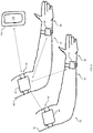
- the system 10 can comprise a master Inertial Measurement Unit (IMU) device 20 that is configured to be attached to an arm 60 of a user.
- the master IMU device 20 can be configured to be attached at a biceps region 62 of the user such as, for example, at or near the biceps or between the shoulder and the elbow of the arm 60 .
- the master IMU device 20 can comprise an attachment member such as a band, a strap, or the like that is sized for the biceps.
- the master IMU device 20 can be configured to provide orientations signals indicative of the orientation of the master IMU device 20 .
- the master IMU device 20 can comprise an IMU processor 22 communicatively coupled to memory 24 .
- the IMU processor 22 can be powered by a battery 26 .
- the IMU processor 22 can be a device that is energy efficient such as, for example, an ultra-low power microcontroller such as, for example, the MSP430 microcontroller by Texas Instruments of Dallas, Tex., U.S.A.
- the master IMU device 20 can comprise an IMU sensor 28 that is communicatively coupled to the IMU processor 22 and configured to detect orientation information.
- the IMU sensor 28 can comprise an accelerometer, a gyroscope and a magnetometer, which can each provide 3-axis data.
- Each component of the IMU sensor 28 can be provided as a separate component or as a system in a package that integrates the accelerometer, the gyroscope and the magnetometer in a monolithic solution such as, for example, the 9-axis inertial modules by ST Microelectronics of Geneva, Switzerland.
- the orientation information can be detected by fusion of the IMU sensor 28 data.
- the each sensor of the IMU sensor 28 can communicate with the IMU processor 22 with a dedicated interrupt line that notifies the IMU processor 22 when new data is ready. Using interrupts can eliminate polling of the sensors and improve power consumption.
- the IMU processor 22 can process the orientation information of the IMU sensor 28 according to a fusion algorithm stored on the memory 24 .
- Suitable fusion algorithms include, but are not limited to, gradient descent method (e.g., the Madgwick Sensor Fusion Algorithm), Kalman filter, extended Kalman filters, or the like. Accordingly, the orientation information of the IMU sensor 28 can be transformed into orientation signals indicative of the orientation, acceleration or both of the master IMU device 20 .
- each axis of the IMU sensor 28 can be calibrated using known energy sources, i.e., angular velocity, gravity, magnetic field, or the like.
- the IMU sensor 28 can be calibrated to correct for offset errors and scale errors by tuning the master IMU device 20 upon manufacture.
- an offset correction, a scale correction, or both can be provided in memory 24 based upon the calibration.
- the IMU processor 22 can calibrate the orientation information of the IMU sensor 28 prior to using the orientation information in the fusion algorithm.
- the offset correction can be configured to compensate for the difference between the IMU sensor 28 output when not stimulated. Accordingly, the offset correction can be determined by averaging the output of the IMU sensor 28 over an unstimulated period of time.
- the scale correction can be configured to compensate for scale errors to a known source of energy.
- the scale correction can be determined by first correcting the IMU sensor 28 output for offset errors, and then taking the ratio of the offset-corrected output of the IMU sensor 28 output to the known source of energy.
- the offset correction can be updated for one or more of the components of the IMU sensor 28 prior to executing the fusion algorithm.
- the IMU processor 22 can periodically execute an offset calibration routine such as, for example, upon startup of the master IMU 20 , at predetermined time intervals, or the like. Accordingly, the IMU processor 22 can periodically update the offset correction for the gyroscope of the IMU sensor 28 by, for example, averaging the gyroscope output for a predetermined period of time while the master IMU 20 is substantially stationary.
- the offset calibration routine can include executing multiple iterations of the fusion algorithm while the master IMU 20 is substantially stationary. Without being bound to theory, it is believed that performing the offset calibration routine for the gyroscope can improve the drift performance of the embodiments provided herein, i.e., the offset calibration routine may contribute to substantially drift free behavior.
- the execution time of the gradient descent method can be improved (i.e., computational time decreased) by using fixed point math functions instead of floating point math functions.
- fixed point math functions For example, square root operations, arithmetic, matrix operations, or combinations thereof can be performed with fixed point functions.
- the overall performance of the fusion algorithm can be improved with fixed point math.
- the Madgwick Sensor Fusion Algorithm was modified by replacing floating point arithmetic functions and square root functions with fixed point functions.
- the ultra-low power microcontroller can use software implemented fixed point functions to improve the orientation accuracy, speed of the algorithm, and power consumption compared to the use of floating point software functions on the ultra-low power microcontroller.
- the software implemented fixed point functions on the ultra-low power microcontroller can consume less power and have a smaller form factor than microcontrollers having hardware implemented floating point functions.
- the master IMU device 20 can comprise low power communication hardware 30 configured to receive and transmit data signals, while consuming a relatively low amount of power.
- the low power communication hardware 30 can be communicatively coupled to the IMU processor 22 .
- the IMU processor 22 can communicate orientation signals with the low power communication hardware 30 .
- the IMU processor 22 can execute the fusion algorithm to process orientation information of the IMU sensor 28 as the information is generated, and relay the orientation signals to the low power communication hardware 30 .
- the IMU sensor 28 can communicate three interrupts indicative of data being available to the IMU processor 22 , i.e., magnetometer events 46 , accelerometer events 48 , and gyroscope events 50 .
- an interrupt can be provided to the IMU processor 22 .
- the IMU processor 22 can be configured to receive the orientation information from the IMU sensor 28 and store the data in memory 24 responsive to each interrupt.
- each falling edge of the magnetometer event 46 , the accelerometer event 48 , and the gyroscope event 50 can trigger a corresponding interrupt.
- the fusion algorithm can be executed by the IMU processor 22 as a fusion algorithm process 52 .
- the fusion algorithm process 52 can be executed in parallel to orientation information retrieval from the IMU sensor 28 . Accordingly, the orientation information can be updated from the IMU sensor 28 and the fusion algorithm process 52 can use the most recently sampled orientation information to determine the orientation signals.
- the magnetometer events 46 , the accelerometer events 48 , and the gyroscope events 50 can be provided at different rates. Specifically, each modality of the IMU sensor 28 can be sampled at different rates.
- the performance of the fusion algorithm can be improved by synchronizing the fusion algorithm process 52 to one of the interrupts, which allows for the orientation information from the IMU sensor 28 to be supplied to the fusion algorithm process 52 with substantially consistent intervals.
- Such synchronization can reduce the occurrence of missing or skipped instances of the orientation information.
- the integration performed by the fusion algorithm and the orientation estimation can be improved through synchronization.
- the IMU processor 22 can iteratively perform the fusion algorithm process 52 , a data relay process 54 , and a power saving process 56 at substantially consistent periods that are synchronized to one of the interrupts.
- the orientation signals can be communicated to the low power communication hardware 30 during the data relay process 54 .
- Power consumption can be reduced by operating the IMU processor 22 in a low power mode during the power saving process 56 .
- the fusion algorithm process 52 has the largest execution time (e.g., less than about 4 ms in the embodiment depicted in FIG. 4 ). Accordingly, lack of synchronization can cause other interrupts to be ignored until the fusion algorithm process 52 is completed, which can decrease performance. Additionally, lack of synchronization can cause the data relay processes 54 to be missed by the IMU processor 22 , which can lead to lack of functionality.
- the utilization of the IMU processor 22 can be about 75%, when the fusion algorithm process 52 takes about 3.7 ms to execute. Moreover, with increased frequency of operation, the orientation accuracy of the fusion algorithm can be improved. Additionally, it is noted that in some embodiments, accuracy can be increased by synchronizing the fusion algorithm process 52 to the event with the fastest sampling rate.
- the master IMU device 20 can be configured to receive orientation signals from one or more additional devices.
- the low power communication hardware 30 can comprise an ANT wireless module by Dynastream Innovations Inc. of Cochrane, Canada. Each ANT wireless module can comprise a low powered RF transceiver. The ANT wireless module can be configured to as a node to interconnect with other nodes, i.e., to interconnect with multiple ANT wireless modules.
- the master IMU device 20 can be configured to receive orientation signals from a node IMU device 40 that are indicative of the orientation, acceleration or both of the node IMU device 40 .
- the low power communication hardware 30 of the master IMU device 20 can receive the orientation signals from the node IMU device 40 and provide the orientation signals of the node IMU device 40 to the IMU processor 22 of the master IMU device 20 .
- the fusion algorithm of the master IMU device 20 can be configured to process the orientation information of the master IMU device 20 and the node IMU device 40 and provide a combined orientation signal indicative of the orientation, acceleration or both of the node IMU device 40 and the master IMU device 20 .
- the node IMU device 40 of the system 10 can be configured to be attached to the arm 60 of the user.
- the node IMU device 40 can be configured to be attached at a forearm region 64 of the user such as, for example, at or near the forearm, or between the wrist and the elbow of the arm 60 .
- the node IMU device 40 can comprise an attachment member such as a band, a strap, or the like that is sized for the forearm.
- the node IMU device 40 can be configured to be attached at a palm region 66 of the user.
- the node IMU device 40 can be configured to provide orientations signals indicative of the orientation, acceleration, or both of the node IMU device 40 .
- the node IMU device 40 can comprise an IMU processor 22 communicatively coupled to memory 24 , a battery 26 , an IMU sensor 28 , and low power communication hardware 30 , as is described above with respect to the master IMU device 20 .
- the IMU processor 22 can utilize the fusion algorithm to transform orientation information of the IMU sensor 28 into orientations signals of the node IMU device 40 .
- the low power communication hardware 30 of the master IMU device 20 and the node IMU device 40 can be communicatively coupled.
- the orientation signals of the node IMU device 40 can be transmitted to the master IMU device 20 .
- BLE can be contrasted with “classic” Bluetooth communications.
- BLE can have lower data transfer rates and shorter range than Bluetooth communications.
- the embodiments described herein utilize the combined orientation signal, which provides the system orientation information efficiently, to transfer orientation information at lower transfer rates. Such efficient or compressed transfer orientation information allows the system 10 to consume less power via BLE, as compared to an implementation utilizing “classic” Bluetooth.
- the combined orientation signal indicative of the orientation, acceleration or both of the master IMU device 20 , the node IMU device 40 , and the second node IMU device 42 . Accordingly, the combined orientation signal can provide orientation information corresponding to the orientation, acceleration or both of three different regions of the body of the user.
- the master IMU device 20 can be attached to the biceps region 62 of the user and the node IMU device 40 can be attached at a forearm region 64 of the user.
- the second node IMU device 42 can be attached at a palm region 66 of the user such as, for example, at or near the hand of the user or between the wrist and finger tips of the user.
- the second node IMU device 42 can comprise an attachment member such as a band, a strap, or the like that is sized for the hand.
- the combined orientation signal of the system 12 can be indicative of the orientation of the biceps region 62 , the forearm region 64 , and the palm region 66 of the user.
- the second node IMU device 42 of the system 12 can be attached at a waist region 68 of the user such as, for example, at or below the umbilicus of the user.
- the second node IMU device 42 can comprise an attachment member such as a band, a strap, or the like that is sized for the waist.
- the combined orientation signal of the system 12 can be indicative of the orientation of the biceps region 62 , the forearm region 64 , and the waist region 68 of the user.
- a three dimensional control system 14 can comprise the master IMU device 20 , the node IMU device 40 , and the second node IMU device 42 , and a third node IMU device 44 .
- the low power mobile interface 32 of the master IMU device 20 can be communicatively coupled to the network interface hardware 110 of the mobile device 100 .
- the third node IMU device 44 can comprise the IMU processor 22 communicatively coupled to memory 24 , the battery 26 , the IMU sensor 28 , and the low power communication hardware 30 , as is described above with respect to the node IMU 20 .
- the low power communication hardware 30 of the master IMU device 20 can be communicatively coupled to the low power communication hardware 30 of each of the node IMU device 40 , the second node IMU device 42 , and the third node IMU device 44 .
- the orientation signals of the node IMU device 40 , the second node IMU device 42 , and the third node IMU device 44 can be transmitted to the master IMU device 20 .
- the low power communication hardware 30 of the master IMU device 20 can receive the orientation signals from the node IMU device 40 , the second node IMU device 42 , and the third node IMU device 44 .
- the orientation signals can be provided to the fusion algorithm of the master IMU device 20 .
- the IMU devices can be configured to operate as a full body detection system.
- the full body detection system can include any number of IMU devices such as, for example, up to the quantity of devices supported by the bandwidth of the low power mobile interface 32 .
- the low power mobile interface 32 comprises a BLE transceiver
- up to about twelve IMU devices can be used.
- the embodiments provided herein further relate to a method 200 which can automatically be executed by the mobile device 100 for providing three dimensional control of the mobile device 100 .
- the method 200 can comprise a process 202 for receiving control input.
- the combined orientation signal indicative of the orientation, acceleration or both of the node IMU device 40 and the master IMU device 20 can be received by the network interface hardware 110 and communicated to the one or more processors 104 .
- the combined orientation signal can be indicative of the orientation, acceleration or both of the second node IMU device 42 , the third node IMU device 44 , or both.
- the control input can be utilized for applications receiving input from one or more users.
- the method 200 can proceed to process 204 .
- the rendered object 210 corresponds to a rendered arm
- a biceps, a forearm, and a wrist of the rendered arm can be manipulated upon the display 108 in accordance with the arm 60 of the user.
- the rendered object 210 can be rendered to mimic the motion of the biceps region 62 , the forearm region 64 , and the waist region 66 .
- multiple rendered objects can be manipulated upon the display 108 according to the combined orientation signal.
- one of the multiple rendered objects can be rendered such that the object is oriented according to the combined orientation signal corresponding to the node IMU device 40 and the master IMU device 20 .
- one of the multiple rendered objects can be rendered such that the object is oriented according to the combined orientation signal corresponding to the second node IMU device 42 and the third node IMU device 44 . Accordingly, multiple rendered objects can be manipulated according to the orientation of the arm 60 and the second arm 70 .
- the rendered object 210 can be displayed with a scene 212 upon the display 100 .
- the scene 212 can comprise one or more scene objects 214 that cannot be manipulated by the rendered object 210 .
- the one or more scene objects 214 can comprise landscape, immovable objects, moving objects or the like.
- the scene 212 can comprise one or more interaction objects 216 that can be manipulated by the rendered object 210 .
- the one or more interaction objects 216 can comprise blocks that can be lifted, pushed, or pulled using the rendered object 210 .
- the method 200 can comprise a process 206 for providing situation awareness.
- one or more reference rays 218 can be rendered upon the display 108 of the mobile device 100 .
- the reference rays 218 can be configured to provide visual feedback indicative of the relative positioning between the rendered object 210 and one of the scene objects 214 .
- the scene object 214 can serve as a datum within the scene 210 . Accordingly, each of the reference rays 218 can project from the datum location to a position upon the rendered object 210 . As the rendered object 210 moves within the scene, the length and angle of the reference rays 218 can change accordingly.
- the change in length and orientation of the reference rays 218 can serve as visual feedback of the correlation between motion of the arm 60 and the rendered object 210 within the scene 212 .
- the reference rays 218 can be provided with respect to a horizontal surface to depict height information, e.g., height relative to a floor, table, and the like. Applicants have discovered that such visual feedback has improved the interaction of users with three dimensional scenes.
- the scene 212 is depicted as comprising nine reference rays 218
- the embodiments described herein can comprise any number of reference rays 218 suitable to provide visual feedback.
- the reference rays can be provided between the rendered object 210 and any number of the scene objects 214 .
- Object rays 220 can be provided from additional ones of the interaction objects 216 such as, for example, the second nearest, the third nearest, etc.
- the object rays 220 can be color coded based upon their rank.
- the interaction objects 216 can be color coded based upon distance from the rendered object 210 . For example, interaction objects 216 within a predefined range can change color or the nearest of the interaction object(s) 216 can change color.
- the rendered object 210 , the scene 212 or both can be rendered from different views to depict perspective.
- the scene can be rendered according to one or more virtual camera to provide three dimensional perspective.
- the position of a virtual cameras utilized to provide rendering can be moved between multiple positions in a manner analogous to alternating head position of the viewer.
- the touch input of the display 108 can receive user tactile input to control movement of the rendered object 210 relative to the scene 212 , i.e., the touch screen gestures can be utilized to navigate throughout an environment.
- an embodiment of the master IMU 20 was tested for drift performance.
- the master IMU 20 executed a modified version of the Madgwick Sensor Fusion Algorithm where floating point arithmetic functions and square root functions were replaced with fixed point functions. Operation of the modified algorithm was synchronized to the gyroscopic sampling rate.
- the master IMU 20 was calibrated and the offset calibration routine was performed prior to collecting drift measurements.
- the drift measurements depicted in FIG. 11 were collected from a statically positioned master IMU 20 .
- the master IMU 20 was placed upon a wooden jig supported by a flat non-ferromagnetic surface with the Y-axis of the IMU sensor 28 aligned vertical, i.e., along the normal of the surface.
- the jig was configured to position the master IMU at an absolute angle with respect to magnetic North.
- the test was repeated in an indoor environment having metallic objects within the room, and outdoors in a location segregated from metallic objects. The test results were independent of the indoor and outdoor environments.
- FIG. 11 depicts the absolute yaw angle data sampled at a rate of one sample per second for 1.4 hours.
- the yaw angle slope of a best fit linear curve demonstrated relatively little drift over time, i.e., less than about 0.2 degree per hour. Specifically, testing demonstrated a yaw angle slope of about less than about 0.1 degrees per hour, or about 0.07 degrees per hour.
- peak-to-peak drift 80 demonstrated relatively little drift over time, i.e., less than about 0.6 degrees throughout an hour. Specifically, testing demonstrated peak-to-peak drift 80 of less than about 0.5 throughout an hour, or about 0.35 degrees throughout an hour. Accordingly, the embodiments described herein can substantially eliminate drift induced errors and improve fine motion detection, which can in turn improve user interaction in game play, augmented reality, or virtual reality simulations.
- the embodiments described herein can be utilized to provide an extension of user's arm that can appear to reach within a three dimensional scene displayed upon a mobile device.
- the arm motion can intuitively grab, move, manipulate and hit objects within the scene in ways not possible with existing devices.
- objects can be grabbed, moved or hit from directions originating from behind the object as well as from other directions by capturing fluid and natural arm movements.
- the fluidity of the user's movement can be enhanced by feedback provided by the situational awareness software components.
- the embodiments described herein can utilize small, lightweight, and wireless sensors, which can reduce cost and improve adoption by users.
- the sensors can additionally include BLE communication, which provides not only a long battery life, but also a gateway to mobile devices as well as an integration path to the Internet of Things. Moreover, the BLE communication provides a communication path to integrate the IMU devices described herein with augmented reality devices, or virtual reality devices.
Landscapes
- Engineering & Computer Science (AREA)
- General Engineering & Computer Science (AREA)
- Theoretical Computer Science (AREA)
- Human Computer Interaction (AREA)
- Physics & Mathematics (AREA)
- General Physics & Mathematics (AREA)
- User Interface Of Digital Computer (AREA)
- Navigation (AREA)
Abstract
Description
Claims (37)
Priority Applications (2)
| Application Number | Priority Date | Filing Date | Title |
|---|---|---|---|
| US15/200,880 US10698501B2 (en) | 2015-07-01 | 2016-07-01 | Systems and methods for three dimensional control of mobile applications |
| US16/713,974 US10845195B2 (en) | 2015-07-01 | 2019-12-13 | System and method for motion based alignment of body parts |
Applications Claiming Priority (3)
| Application Number | Priority Date | Filing Date | Title |
|---|---|---|---|
| US201562187426P | 2015-07-01 | 2015-07-01 | |
| US201562221170P | 2015-09-21 | 2015-09-21 | |
| US15/200,880 US10698501B2 (en) | 2015-07-01 | 2016-07-01 | Systems and methods for three dimensional control of mobile applications |
Related Child Applications (1)
| Application Number | Title | Priority Date | Filing Date |
|---|---|---|---|
| US16/713,974 Continuation-In-Part US10845195B2 (en) | 2015-07-01 | 2019-12-13 | System and method for motion based alignment of body parts |
Publications (2)
| Publication Number | Publication Date |
|---|---|
| US20170024024A1 US20170024024A1 (en) | 2017-01-26 |
| US10698501B2 true US10698501B2 (en) | 2020-06-30 |
Family
ID=56550344
Family Applications (1)
| Application Number | Title | Priority Date | Filing Date |
|---|---|---|---|
| US15/200,880 Active 2036-12-21 US10698501B2 (en) | 2015-07-01 | 2016-07-01 | Systems and methods for three dimensional control of mobile applications |
Country Status (2)
| Country | Link |
|---|---|
| US (1) | US10698501B2 (en) |
| WO (1) | WO2017004544A1 (en) |
Families Citing this family (8)
| Publication number | Priority date | Publication date | Assignee | Title |
|---|---|---|---|---|
| CN107272907B (en) * | 2017-07-10 | 2020-08-07 | 三星电子(中国)研发中心 | A method and device for scene interruption and connection based on virtual reality technology |
| CN108132053B (en) * | 2017-11-24 | 2020-01-07 | 北京工商大学 | A pedestrian trajectory construction method, system and inertial measurement device |
| CN108762489B (en) * | 2018-05-07 | 2021-09-21 | 武汉灏存科技有限公司 | Control method based on data glove, system and storage medium |
| TWI681170B (en) * | 2018-12-22 | 2020-01-01 | 國立清華大學 | Calibration method of multiple inertial measurement units on multi-linkage system |
| US11493989B2 (en) * | 2019-11-08 | 2022-11-08 | Magic Leap, Inc. | Modes of user interaction |
| JP7435357B2 (en) * | 2020-08-18 | 2024-02-21 | トヨタ自動車株式会社 | Operating state monitoring system, training support system, operating state monitoring system control method, and control program |
| US11221493B1 (en) * | 2021-02-03 | 2022-01-11 | Jamaul Baker | Virtual reality body suit assembly |
| EP4728241A2 (en) * | 2023-07-11 | 2026-04-22 | Berlin, Edwin, P. | Motion capture sensor with compensation for drift and saturation |
Citations (15)
| Publication number | Priority date | Publication date | Assignee | Title |
|---|---|---|---|---|
| US20050253806A1 (en) * | 2004-04-30 | 2005-11-17 | Hillcrest Communications, Inc. | Free space pointing devices and methods |
| US20090070566A1 (en) * | 2007-07-06 | 2009-03-12 | Joerg Schreiner | Electronic Device With CPU and Interrupt Relay Stage |
| US20090138746A1 (en) * | 2007-11-28 | 2009-05-28 | Daniel Richard Klemer | Method For Efficient Software Generation Of Multiple Pulse Width Modulated Signals |
| US20110254760A1 (en) * | 2010-04-20 | 2011-10-20 | Invensense, Inc. | Wireless Motion Processing Sensor Systems Suitable for Mobile and Battery Operation |
| US20130222565A1 (en) * | 2012-02-28 | 2013-08-29 | The Johns Hopkins University | System and Method for Sensor Fusion of Single Range Camera Data and Inertial Measurement for Motion Capture |
| US20130254582A1 (en) * | 2012-03-23 | 2013-09-26 | Yokogawa Electric Corporation | Synchronization apparatus and field device |
| US20140278217A1 (en) | 2013-03-15 | 2014-09-18 | Invensense, Inc. | Method to reduce data rates and power consumption using device based attitude quaternion generation |
| US20150177020A1 (en) * | 2012-08-02 | 2015-06-25 | Memsic, Inc. | Method and apparatus for data fusion of a three-axis magnetometer and three axis accelerometer |
| US9068843B1 (en) * | 2014-09-26 | 2015-06-30 | Amazon Technologies, Inc. | Inertial sensor fusion orientation correction |
| US20150220109A1 (en) * | 2013-11-29 | 2015-08-06 | Mechio Inc. | Wearable computing device |
| US20150288687A1 (en) * | 2014-04-07 | 2015-10-08 | InvenSense, Incorporated | Systems and methods for sensor based authentication in wearable devices |
| US20160091955A1 (en) * | 2014-09-26 | 2016-03-31 | Qualcomm Incorporated | Algorithm engine for ultra low-power processing of sensor data |
| US20160363460A1 (en) * | 2015-06-12 | 2016-12-15 | 7725965 Canada Inc. | Orientation model for inertial devices |
| US20160378265A1 (en) * | 2014-03-17 | 2016-12-29 | Wacom Co., Ltd. | Position detecting device |
| US9785247B1 (en) * | 2014-05-14 | 2017-10-10 | Leap Motion, Inc. | Systems and methods of tracking moving hands and recognizing gestural interactions |
-
2016
- 2016-07-01 US US15/200,880 patent/US10698501B2/en active Active
- 2016-07-01 WO PCT/US2016/040737 patent/WO2017004544A1/en not_active Ceased
Patent Citations (15)
| Publication number | Priority date | Publication date | Assignee | Title |
|---|---|---|---|---|
| US20050253806A1 (en) * | 2004-04-30 | 2005-11-17 | Hillcrest Communications, Inc. | Free space pointing devices and methods |
| US20090070566A1 (en) * | 2007-07-06 | 2009-03-12 | Joerg Schreiner | Electronic Device With CPU and Interrupt Relay Stage |
| US20090138746A1 (en) * | 2007-11-28 | 2009-05-28 | Daniel Richard Klemer | Method For Efficient Software Generation Of Multiple Pulse Width Modulated Signals |
| US20110254760A1 (en) * | 2010-04-20 | 2011-10-20 | Invensense, Inc. | Wireless Motion Processing Sensor Systems Suitable for Mobile and Battery Operation |
| US20130222565A1 (en) * | 2012-02-28 | 2013-08-29 | The Johns Hopkins University | System and Method for Sensor Fusion of Single Range Camera Data and Inertial Measurement for Motion Capture |
| US20130254582A1 (en) * | 2012-03-23 | 2013-09-26 | Yokogawa Electric Corporation | Synchronization apparatus and field device |
| US20150177020A1 (en) * | 2012-08-02 | 2015-06-25 | Memsic, Inc. | Method and apparatus for data fusion of a three-axis magnetometer and three axis accelerometer |
| US20140278217A1 (en) | 2013-03-15 | 2014-09-18 | Invensense, Inc. | Method to reduce data rates and power consumption using device based attitude quaternion generation |
| US20150220109A1 (en) * | 2013-11-29 | 2015-08-06 | Mechio Inc. | Wearable computing device |
| US20160378265A1 (en) * | 2014-03-17 | 2016-12-29 | Wacom Co., Ltd. | Position detecting device |
| US20150288687A1 (en) * | 2014-04-07 | 2015-10-08 | InvenSense, Incorporated | Systems and methods for sensor based authentication in wearable devices |
| US9785247B1 (en) * | 2014-05-14 | 2017-10-10 | Leap Motion, Inc. | Systems and methods of tracking moving hands and recognizing gestural interactions |
| US9068843B1 (en) * | 2014-09-26 | 2015-06-30 | Amazon Technologies, Inc. | Inertial sensor fusion orientation correction |
| US20160091955A1 (en) * | 2014-09-26 | 2016-03-31 | Qualcomm Incorporated | Algorithm engine for ultra low-power processing of sensor data |
| US20160363460A1 (en) * | 2015-06-12 | 2016-12-15 | 7725965 Canada Inc. | Orientation model for inertial devices |
Non-Patent Citations (2)
| Title |
|---|
| International Search Report in International Application No. PCT/US2016/040737, dated Nov. 23, 2016, 5 pages. |
| Written Opinion in International Application No. PCT/US2016/040737, dated Nov. 23, 2016, 9 pages. |
Also Published As
| Publication number | Publication date |
|---|---|
| WO2017004544A1 (en) | 2017-01-05 |
| US20170024024A1 (en) | 2017-01-26 |
Similar Documents
| Publication | Publication Date | Title |
|---|---|---|
| US10698501B2 (en) | Systems and methods for three dimensional control of mobile applications | |
| KR20170136750A (en) | Electronic apparatus and operating method thereof | |
| CN104956648B (en) | Method and apparatus for sensing the orientation of object in space in fixed reference frame | |
| RU2015111261A (en) | LIGHT SOURCE MANAGEMENT THROUGH A PORTABLE DEVICE | |
| CN104145474A (en) | guided image capture | |
| WO2021013230A1 (en) | Robot control method, robot, terminal, server, and control system | |
| KR20160070780A (en) | Refocusable images | |
| CN107407559A (en) | Range image acquisition device and range image acquisition methods | |
| US20180012372A1 (en) | Distance image acquisition apparatus and distance image acquisition method | |
| CN104246664B (en) | A virtual touch device with a transparent display that does not display a pointer | |
| CN103278246A (en) | Thermal infrared imager based on Android system | |
| WO2013123868A1 (en) | Data acquisition method, device and mobile terminal | |
| US10972635B2 (en) | Synchronizing wireless sensor data and video | |
| KR20130119233A (en) | Apparatus for acquiring 3 dimension virtual object information without pointer | |
| WO2015180588A1 (en) | Gesture remote control apparatus, gesture receiving apparatus, wireless remote control system and method for operating terminal device | |
| KR20150076186A (en) | Motion compensation in an interactive display system | |
| WO2017005070A1 (en) | Display control method and device | |
| US8130134B2 (en) | Reduced instruction set television control system and method of use | |
| CN103529961A (en) | Handheld terminal control device and control method | |
| US9606639B2 (en) | Pointing system and display having improved operable range | |
| KR20160050863A (en) | Method for processing sensor value to motion recognition and apparatus using the same | |
| CN109542218A (en) | A kind of mobile terminal, man-machine interactive system and method | |
| CN104699228B (en) | A kind of intelligence TV screen terminal mouse method and systems | |
| US10002406B2 (en) | Consistent spherical photo and video orientation correction | |
| CN103269400A (en) | Method for turning over system screen of mobile communication equipment |
Legal Events
| Date | Code | Title | Description |
|---|---|---|---|
| AS | Assignment |
Owner name: OHIO STATE INNOVATION FOUNDATION, OHIO Free format text: ASSIGNMENT OF ASSIGNORS INTEREST;ASSIGNORS:ZHAO, XIAOXI;OZYALCIN, ANIL;SIGNING DATES FROM 20160524 TO 20160602;REEL/FRAME:039108/0087 Owner name: SOLITONREACH INC, OHIO Free format text: ASSIGNMENT OF ASSIGNORS INTEREST;ASSIGNOR:KHAN, FURRUKH;REEL/FRAME:039107/0899 Effective date: 20160524 |
|
| STPP | Information on status: patent application and granting procedure in general |
Free format text: NON FINAL ACTION MAILED |
|
| STPP | Information on status: patent application and granting procedure in general |
Free format text: RESPONSE TO NON-FINAL OFFICE ACTION ENTERED AND FORWARDED TO EXAMINER |
|
| STPP | Information on status: patent application and granting procedure in general |
Free format text: FINAL REJECTION MAILED |
|
| STPP | Information on status: patent application and granting procedure in general |
Free format text: DOCKETED NEW CASE - READY FOR EXAMINATION |
|
| STPP | Information on status: patent application and granting procedure in general |
Free format text: NON FINAL ACTION MAILED |
|
| STPP | Information on status: patent application and granting procedure in general |
Free format text: RESPONSE TO NON-FINAL OFFICE ACTION ENTERED AND FORWARDED TO EXAMINER |
|
| STPP | Information on status: patent application and granting procedure in general |
Free format text: NOTICE OF ALLOWANCE MAILED -- APPLICATION RECEIVED IN OFFICE OF PUBLICATIONS |
|
| STCF | Information on status: patent grant |
Free format text: PATENTED CASE |
|
| MAFP | Maintenance fee payment |
Free format text: PAYMENT OF MAINTENANCE FEE, 4TH YR, SMALL ENTITY (ORIGINAL EVENT CODE: M2551); ENTITY STATUS OF PATENT OWNER: SMALL ENTITY Year of fee payment: 4 |