US106981A - Improvement in corn-planters - Google Patents
Improvement in corn-planters Download PDFInfo
- Publication number
- US106981A US106981A US106981DA US106981A US 106981 A US106981 A US 106981A US 106981D A US106981D A US 106981DA US 106981 A US106981 A US 106981A
- Authority
- US
- United States
- Prior art keywords
- corn
- rods
- bar
- planters
- machine
- Prior art date
- Legal status (The legal status is an assumption and is not a legal conclusion. Google has not performed a legal analysis and makes no representation as to the accuracy of the status listed.)
- Expired - Lifetime
Links
- XEEYBQQBJWHFJM-UHFFFAOYSA-N Iron Chemical compound [Fe] XEEYBQQBJWHFJM-UHFFFAOYSA-N 0.000 description 8
- 240000008042 Zea mays Species 0.000 description 6
- 235000005824 Zea mays ssp. parviglumis Nutrition 0.000 description 6
- 235000002017 Zea mays subsp mays Nutrition 0.000 description 6
- 235000005822 corn Nutrition 0.000 description 6
- 229910052742 iron Inorganic materials 0.000 description 4
- 238000010276 construction Methods 0.000 description 2
- 239000011435 rock Substances 0.000 description 2
- 238000006809 Jones oxidation reaction Methods 0.000 description 1
- 229910000831 Steel Inorganic materials 0.000 description 1
- 238000005266 casting Methods 0.000 description 1
- 239000003550 marker Substances 0.000 description 1
- 239000010959 steel Substances 0.000 description 1
Images

Classifications
-
- A—HUMAN NECESSITIES
- A01—AGRICULTURE; FORESTRY; ANIMAL HUSBANDRY; HUNTING; TRAPPING; FISHING
- A01C—PLANTING; SOWING; FERTILISING
- A01C7/00—Sowing
- A01C7/18—Machines for depositing quantities of seed at intervals
Definitions
- MICHAEL AOKERMAN OF STEAMBOAT ROCK, IOWA.
- A represents the frame; B B, the coveringwheels, and (J O the runners,which are the same, or nearly the same, as on machines now in use.
- D On the upper part of each runner is fastened a thin iron slab, D, of suitable width, which acts as a gage to let the runners plow in the ground a uniform depth.
- E On the point of the runners O G are steel knives E, and on the heels are the boxes G G, fastened by set-screws.
- the box Gr with the plunger a is like the one on J. H. Joness improved hand-planter, patented August 26, 1856, and April 9, 1867, with the exception that in mine the plunger is of uniform width from top to bottom.
- the casting G that holds the plunger to its place is made box-like, as shown, with a spring, b, to hold the corn until the plunger drives it through.
- a rod, f is pivoted in one of these forks, and runs back, having the axle of the droppingwheels I passing through its rear end.
- Another rod, g, pivoted in the other fork of said bar 6 runs under the axle of the dropping- Forward and outside of the frame wheels, and then takes a short bend upward, having a forked bar, h, pivoted to it.
- the upper end of this bar h is also forked and pivoted to a bar, it, which runs from a standard, J, on a cross-beam, K, back of the coveringwheels B B, forward to and in a mortise on the cross-bar H.
- the front ends of the rods k 75 are loose in the mortises 011 the crossbar H, so that they can move back and forth.
- the lever L is also to drop the corn by hand, as will be hereinafter described.
- the rods 9 y when they reach the center of the covering wheels B, are flattened and brought to an edge next the wheel, so as to catch in a ratchet-wheel, m, fastened to the covering-wheel, as shown.
- the object of this is that in a field that is cloddy and uneven the rods g g, with all their attachments, will be carried upward while the machine goes over two and a half or three feet of ground, then thrown inside the spring.
- the lower edge of said spring is so bent as to hold the rod 9 until the dropper-wheels fall in the furrow, and gives these rods a tap and plunges the corn. It will also throw the rod in the ratchet-wheel, so that it cannot drop corn until the machine goes two and a half or three feet farther, and so near the other furrow that there will be no danger of dropping between furrows.
- the dropper-wheels I not being attached to the rods 9 g, can fly up as they roll over clods, and do no harm.
- the field must bewell harrowed, so it is even, and furrowed out with a good marker, so it leaves a furrow one and a half or two inches deep and from five to six inches wide on top.
Landscapes
- Life Sciences & Earth Sciences (AREA)
- Soil Sciences (AREA)
- Environmental Sciences (AREA)
- Soil Working Implements (AREA)
Description
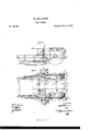
M. ACKERMANN'.
Corn Planter. I
No. 106,981. Patented Sept. 6, 1870.
J: m JrrP N. PETERS. Phcto-Ulhagnphur. wnihin xm nc.
FFIGE.
MICHAEL AOKERMAN, OF STEAMBOAT ROCK, IOWA.
IMPROVEMENT IN CORN-PLANTERS.
Specification forming part of Letters Patent No. 106,981, dated September 6, 1870.
To all whom it may concern Be it known that I, MICHAEL ACKERMAN, of Steamboat Rock, in the county of Hardin and State of Iowa, have invented certain new and useful Improvements in Corn-Planters; and I do hereby declare that the following is a full, clear, and exact description thereof, reference being had to the accompanying drawings, and to the letters of reference marked thereon, which form a part of this specification.
The nature of my invention consists in the construction and arrangement of a corn-planter, as will be hereinafter set forth.
In order to enable others skilled in the art to which my invention appertains to make and use the same, I will now proceed to describe its construction and operation, referring to the annexed drawings, in which- Figure 1 is a side elevation, and Fig. 2 is a plan view, of my machine.
A represents the frame; B B, the coveringwheels, and (J O the runners,which are the same, or nearly the same, as on machines now in use. On the upper part of each runner is fastened a thin iron slab, D, of suitable width, which acts as a gage to let the runners plow in the ground a uniform depth. On the point of the runners O G are steel knives E, and on the heels are the boxes G G, fastened by set-screws.
The box Gr with the plunger a is like the one on J. H. Joness improved hand-planter, patented August 26, 1856, and April 9, 1867, with the exception that in mine the plunger is of uniform width from top to bottom.
The casting G that holds the plunger to its place is made box-like, as shown, with a spring, b, to hold the corn until the plunger drives it through.
To the plunger a is fastened a rod, (7, which has an eye on its upper end, and is inserted in a small mortise on a cross-bar, H, in such a way that either side may work independent of the other. A, on each side, is fastened an iron bar, 6, having a double fork at its lower end.
A rod, f, is pivoted in one of these forks, and runs back, having the axle of the droppingwheels I passing through its rear end. Another rod, g, pivoted in the other fork of said bar 6, runs under the axle of the dropping- Forward and outside of the frame wheels, and then takes a short bend upward, having a forked bar, h, pivoted to it. The upper end of this bar h is also forked and pivoted to a bar, it, which runs from a standard, J, on a cross-beam, K, back of the coveringwheels B B, forward to and in a mortise on the cross-bar H.
The front ends of the rods k 75 are loose in the mortises 011 the crossbar H, so that they can move back and forth. There is also a lever, L, running crosswise in the middle of the machine, with two chains, i i, connecting with the axle of the dropping-wheels I I, to hold said wheels up in going to or from the field and when turning the machine. The lever L is also to drop the corn by hand, as will be hereinafter described.
The rods 9 y, when they reach the center of the covering wheels B, are flattened and brought to an edge next the wheel, so as to catch in a ratchet-wheel, m, fastened to the covering-wheel, as shown.
On the standard J ,runnin g downward from the cross-beam K, is an iron, M, running forward near the center of the covering-wheel, said iron having at its front end a pair of jaws, n a, bent downward, and a spring, 19, between said jaws. In this the end of the rod g will so play as to throw itself out and in of the ratchet-wheel.
The object of this is that in a field that is cloddy and uneven the rods g g, with all their attachments, will be carried upward while the machine goes over two and a half or three feet of ground, then thrown inside the spring. The lower edge of said spring is so bent as to hold the rod 9 until the dropper-wheels fall in the furrow, and gives these rods a tap and plunges the corn. It will also throw the rod in the ratchet-wheel, so that it cannot drop corn until the machine goes two and a half or three feet farther, and so near the other furrow that there will be no danger of dropping between furrows. The dropper-wheels I, not being attached to the rods 9 g, can fly up as they roll over clods, and do no harm.
The field must bewell harrowed, so it is even, and furrowed out with a good marker, so it leaves a furrow one and a half or two inches deep and from five to six inches wide on top.
In working the machine the driver will sit so as to balance the machine to suit, and as soon as the machine crosses a cross-furrow the dropping-wheels fall in the furrow and bear down on rods g 9. These rods will pull down the plungers by the rods h h and 70 7c, and plunge the corn out, feeding itself.
In a field where the ground is so bad that this self-planter cannot be used, take off all rods and dropping-wheels belonging to the self-dropper, except the cross-bar H, the rods d d, and plungers a a; then attach the small rods t t, fastened on the cross-bar H, to the lever L, and the machine is a complete handplanter.
Having thus fully described my invention,
Publications (1)
| Publication Number | Publication Date |
|---|---|
| US106981A true US106981A (en) | 1870-09-06 |
Family
ID=2176457
Family Applications (1)
| Application Number | Title | Priority Date | Filing Date |
|---|---|---|---|
| US106981D Expired - Lifetime US106981A (en) | Improvement in corn-planters |
Country Status (1)
| Country | Link |
|---|---|
| US (1) | US106981A (en) |
Cited By (1)
| Publication number | Priority date | Publication date | Assignee | Title |
|---|---|---|---|---|
| DE3234747A1 (en) * | 1982-09-20 | 1984-03-22 | Thyssen Plastik Anger KG, 8000 München | DISTRIBUTION SYSTEM FOR FLOWING MEDIA |
-
0
- US US106981D patent/US106981A/en not_active Expired - Lifetime
Cited By (1)
| Publication number | Priority date | Publication date | Assignee | Title |
|---|---|---|---|---|
| DE3234747A1 (en) * | 1982-09-20 | 1984-03-22 | Thyssen Plastik Anger KG, 8000 München | DISTRIBUTION SYSTEM FOR FLOWING MEDIA |
Similar Documents
| Publication | Publication Date | Title |
|---|---|---|
| US106981A (en) | Improvement in corn-planters | |
| US2040A (en) | And rufus | |
| US86307A (en) | Improvement in combined seed-sower and cultivator | |
| US119628A (en) | Improvement in ground-markers and furrowers | |
| US58798A (en) | Improvement in corn and cane planters | |
| US9893A (en) | Improvement in seed-planters | |
| US108044A (en) | Improvement in corn-planters and markers | |
| US54139A (en) | Improvement in combined seeder and cultivator | |
| US102201A (en) | Improvement in cultivators | |
| US110187A (en) | Improvement in planters and cultivators | |
| US7544A (en) | Improvement in seed-planters | |
| US93680A (en) | Improvement in gang-plows | |
| US56970A (en) | Improvement in machines for marking ground for planting | |
| US12557A (en) | Improvement in seed-planters | |
| US120507A (en) | Improvement in walking-planters | |
| US64152A (en) | Improvement in gang-plough | |
| US94289A (en) | Improvement in combined planter and cultivator | |
| US152494A (en) | Improvement in corn-planters | |
| US303573A (en) | Corn-planter | |
| US2540A (en) | Improvement in corn-cultivators | |
| US208668A (en) | Improvement in corn-planters | |
| US100495A (en) | Improvement in corn-planters | |
| US361935A (en) | Dropping and marking attachment for corn-planters | |
| US756722A (en) | Corn or cotton planter. | |
| US98886A (en) | Improvement in corn-planter and fertilizer |