US10698038B2 - Multichannel ground fault tester - Google Patents
Multichannel ground fault tester Download PDFInfo
- Publication number
- US10698038B2 US10698038B2 US15/729,752 US201715729752A US10698038B2 US 10698038 B2 US10698038 B2 US 10698038B2 US 201715729752 A US201715729752 A US 201715729752A US 10698038 B2 US10698038 B2 US 10698038B2
- Authority
- US
- United States
- Prior art keywords
- current sensor
- circuit
- channel
- state
- tester
- Prior art date
- Legal status (The legal status is an assumption and is not a legal conclusion. Google has not performed a legal analysis and makes no representation as to the accuracy of the status listed.)
- Active, expires
Links
- 238000012360 testing method Methods 0.000 claims abstract description 66
- 238000002955 isolation Methods 0.000 description 14
- 238000012423 maintenance Methods 0.000 description 6
- 238000012544 monitoring process Methods 0.000 description 4
- 230000000694 effects Effects 0.000 description 3
- 238000007689 inspection Methods 0.000 description 2
- 230000007246 mechanism Effects 0.000 description 2
- 230000004913 activation Effects 0.000 description 1
- 238000013459 approach Methods 0.000 description 1
- 230000009849 deactivation Effects 0.000 description 1
- 238000009434 installation Methods 0.000 description 1
- 230000007257 malfunction Effects 0.000 description 1
- 238000000034 method Methods 0.000 description 1
- 230000007935 neutral effect Effects 0.000 description 1
Images


Classifications
-
- G—PHYSICS
- G01—MEASURING; TESTING
- G01R—MEASURING ELECTRIC VARIABLES; MEASURING MAGNETIC VARIABLES
- G01R31/00—Arrangements for testing electric properties; Arrangements for locating electric faults; Arrangements for electrical testing characterised by what is being tested not provided for elsewhere
- G01R31/50—Testing of electric apparatus, lines, cables or components for short-circuits, continuity, leakage current or incorrect line connections
- G01R31/52—Testing for short-circuits, leakage current or ground faults
-
- B61L27/0055—
-
- B61L27/0088—
-
- B—PERFORMING OPERATIONS; TRANSPORTING
- B61—RAILWAYS
- B61L—GUIDING RAILWAY TRAFFIC; ENSURING THE SAFETY OF RAILWAY TRAFFIC
- B61L27/00—Central railway traffic control systems; Trackside control; Communication systems specially adapted therefor
- B61L27/50—Trackside diagnosis or maintenance, e.g. software upgrades
- B61L27/53—Trackside diagnosis or maintenance, e.g. software upgrades for trackside elements or systems, e.g. trackside supervision of trackside control system conditions
-
- B—PERFORMING OPERATIONS; TRANSPORTING
- B61—RAILWAYS
- B61L—GUIDING RAILWAY TRAFFIC; ENSURING THE SAFETY OF RAILWAY TRAFFIC
- B61L27/00—Central railway traffic control systems; Trackside control; Communication systems specially adapted therefor
- B61L27/60—Testing or simulation
-
- B—PERFORMING OPERATIONS; TRANSPORTING
- B61—RAILWAYS
- B61L—GUIDING RAILWAY TRAFFIC; ENSURING THE SAFETY OF RAILWAY TRAFFIC
- B61L29/00—Safety means for rail/road crossing traffic
Definitions
- Embodiments disclosed herein relate to ground fault testing and, more particularly, to a multichannel ground fault tester suitable for testing, among other things, railroad crossing equipment.
- Crossing gates which typically are raised by default and lowered when a train approaches and crosses an intersection of a road and railroad track (i.e., a crossing), may be provided for roadway and pedestrian safety. In some instances, there may be separate gates for the roadway and the pedestrian path. For public safety reasons, it is essential that these crossing gates operate correctly.
- Railroad crossing gates utilize electrical and mechanical components to ensure that the gates perform their intended functions correctly.
- One way to ensure that the crossing gates operate correctly is to make sure that its circuitry is properly isolated from ground or earth—i.e., the circuitry is not experiencing a ground fault.
- a ground fault occurs when an energized portion of a solidly-grounded electrical system becomes unintentionally connected with a path to ground or the earth. When this happens, the system phase-to-ground voltage can cause harmful and excessive levels of current to flow through the unintentional path or inadvertently provide energy to vital circuits thereby changing the intended state from restrictive to non-restrictive.
- GFTs ground fault testers
- Embodiments disclosed herein provide a multichannel ground fault tester that can be connected to multiple individual circuits (or nodes isolated from each other within a circuit) at the same time.
- the circuits or nodes can be tested sequentially, or in any order, without manually disconnecting, moving and reconnecting the tester as is currently required when using a single-channel GFT to test multiple circuits (or nodes isolated from each other within a circuit).
- a ground fault testing device comprising a signal generator adapted to output a test signal; a current sensor adapted to be connected to a first potential; and a plurality of channels connected to receive the test signal, each channel being adapted to connect the current sensor to a respective external circuit when placed in a first state and adapted to connect the current sensor to an internal circuit when placed in a second state.
- the current sensor is adapted to sense a level of a current flowing through each channel and its respective external circuit when each channel is placed in the first state.
- a ground fault testing apparatus comprising a housing having a front panel; a signal generator within the housing and being adapted to output a test signal; a current sensor within the housing and being adapted to be connected to a ground potential via a first connection point through the front panel; a plurality of channels within the housing and being connected to receive the test signal, each channel being adapted to connect the current sensor to a respective external circuit via a respective connection point through the front panel when placed in a first state and adapted to connect the current sensor to an internal circuit when placed in a second state; a first circuit connected to the current sensor and comprising a plurality of indicators visible through the front panel of the housing, wherein the current sensor is adapted to sense a level of a current flowing through each channel and its respective external circuit when each channel is placed in the first state.
- FIG. 1 illustrates an example of a single-channel ground fault tester connected to and testing a single electrical circuit.
- FIG. 2 illustrates an example of multiple single-channel ground fault testers, each respectively connected to and testing an individual circuit/node.
- FIG. 3 illustrates the configuration of a single-channel ground fault tester and its connections for testing a single electrical circuit.
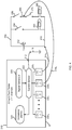
- FIG. 4 illustrates the configuration of a multichannel ground fault tester constructed in accordance with the disclosed principles and its connections for testing multiple electrical circuits/nodes.
- FIG. 5 illustrates an example of a vital relay channel used in the multichannel ground fault tester illustrated in FIG. 4 .
- FIG. 6 illustrates an example front panel of the multichannel ground fault tester illustrated in FIG. 4 .
- the disclosed embodiments provide a multichannel ground fault tester that can be connected to multiple individual circuits (or nodes isolated from each other within a circuit) at the same time.
- the circuits or nodes can be tested sequentially, or in any order, without manually disconnecting, moving and reconnecting the tester as is currently required when using a single-channel GFT to test multiple circuits (or nodes isolated from each other within a circuit).
- the disclosed multichannel ground fault tester therefore automates testing of multiple circuits (or nodes isolated from each other within a circuit) and eliminates the need for maintenance personnel to manually connect the tester to each circuit/node, thereby reducing maintenance activities, labor time and costs.
- isolation between circuits e.g., signal lamps, relays, etc.
- ground fault tester In the railroad industry, inspections for ground isolation can be done annually or continually if a ground fault tester is hardwired to the circuits to be checked.
- the circuits in question have a common return (e.g., negative, positive, neutral).
- isolation testing between the common return and ground can be used to test for and identify an isolation failure (i.e., a ground fault).
- FIG. 1 illustrates an example of a single-channel ground fault tester 10 connected to and testing an electrical circuit 50 .
- the tester 10 has a first connection 12 to a ground potential 16 and a second connection 14 to a common return node 70 in the circuit 50 .
- the connections 12 , 14 could be e.g., cabled or wired leads that are clamped to or permanently hardwired to terminals or other connection points of the ground potential 16 or return node 70 , respectively.
- the ground fault tester 10 typically comprises an indicator and/or alarm feature for providing an indication when there is a ground fault in the circuit 50 (i.e., lack of sufficient isolation in the circuit 50 ).
- the ground fault tester 10 may comprise a digital and/or analog status output that may be attached to other monitoring and/or reporting equipment as is known in the art.
- the example circuit 50 comprises a battery 52 , a first relay 54 connected in series with a first signal lamp 64 , a second relay 56 connected in series with a second signal lamp 66 , and a third relay 58 connected in series with a third signal lamp 68 .
- the battery 52 provides the path to node 70 for receiving and distributing a test signal to all of the battery positive terminal connections within the circuit 50 . This way, the entire circuit 50 may be checked for a proper isolation from ground.
- the ground fault tester 10 applies a test signal to the circuit 50 via connection 14 and senses the level of the current flow within the circuit 50 . If the level of the current flow is below a predetermined threshold level, the circuit 50 is deemed isolated by the tester 10 .
- the tester 10 may provide an indication that the circuit 50 is properly isolated from ground. Suitable indications include, but are not limited to, illuminating a colored LED/light bulb on the tester 10 (e.g., a green LED/light bulb) or providing some other digital and/or analog output that can be transmitted to monitoring and/or reporting equipment.
- the tester 10 may provide one or more indicators, alarms and/or outputs informing the user of the ground fault. Suitable indicators, alarms and outputs include, but are not limited to, illuminating/flashing a colored LED/light bulb on the tester 10 (e.g., a red LED/light bulb), providing an audible indication from the tester 10 (e.g., a bell or buzzer), or providing some other digital and/or analog output that can be transmitted to monitoring and/or reporting equipment.
- FIG. 2 illustrates an example where two single-channel ground fault testers 10 , 110 are used to test separate nodes (i.e., separate circuits) within a circuit 150 .
- the example circuit 150 comprises a battery 152 , a first relay 154 connected in series with a first signal lamp 164 , a second relay 156 connected in series with a second signal lamp 166 , and third and fourth relays 158 , 172 connected in series with a third signal lamp 168 .
- the third and fourth relays 158 , 172 create a node 180 that is isolated from the rest of the circuit 150 and the first return node 170 .
- all of the circuits/nodes of circuit 150 cannot be checked for proper isolation from ground using one single-channel ground fault tester unless the tester is disconnected from the first node 170 and then connected to the second node 180 or two separate testers 10 , 110 are used as illustrated in FIG. 2 .
- the first tester 10 has a first connection 12 to a ground potential 16 and a second connection 14 to the first return node 170 in the circuit 150 .
- the connections 12 , 14 could be e.g., cabled or wired leads that are clamped to or permanently hardwired to terminals or other connection points of the ground potential 16 or return node 170 , respectively.
- the second tester 110 has a first connection 112 to a ground potential 116 and a second connection 114 to the second return node 180 .
- the connections 112 , 114 could be e.g., cabled or wired leads that are clamped to or permanently hardwired to terminals or other connection points of the ground potential 116 or return node 180 , respectively.
- each ground fault tester 10 , 110 typically comprises an indicator and/or alarm feature for providing indications when there is a ground fault in the circuit/node being tested.
- each ground fault tester 10 , 110 may comprise a digital and/or analog status output that may be attached to other monitoring and/or reporting equipment as is known in the art.
- ground fault testers generally follow the topology shown in FIG. 3 , which illustrates the topology for the example ground fault tester 10 illustrated in FIGS. 1 and 2 .
- the tester 10 includes a signal generator 20 electrically connected to a current sensor 22 .
- the current sensor 22 is electrically connected to an indicators/alarms circuit 26 having one or more indicators/outputs as discussed above.
- the tester 10 may also include a processor, logic device (e.g., CPLC, FPGA) or other type of controller for controlling the operation of the signal generator 20 , current sensor 22 and/or indicators/alarms circuit 26 .
- the current sensor 22 is also connected to a ground potential 16 via a first connection 12 and to a return 270 of a circuit 250 via a second connection 14 .
- the connections 12 , 14 can be the type of connections discussed above.
- the example circuit 250 comprises a battery 252 and a relay 254 connected in series with a signal lamp 264 .
- the signal generator 20 outputs a test signal through the current sensor 22 and second connection 14 to the circuit 250 .
- the current sensor 22 detects the level of the signal as it is applied to the circuit 250 and compares that level to a predetermined threshold level. If it is determined that the level of the current flowing through the circuit 250 is below the predetermined threshold level, the circuit 250 is deemed isolated.
- the current sensor 22 may provide an output to the indicators/alarms circuit 26 , causing the circuit 26 to activate one or more indicators, and/or provide some other output, informing the user that the circuit 250 under test is properly isolated from ground.
- the current sensor 22 provides an output to the indicators/alarms circuit 26 , causing the circuit 26 to activate one or more indicators/alarms, and/or provide some other output, informing the user that the circuit 250 is not properly isolated from ground (i.e., the circuit 250 has a ground fault). Suitable indicators, alarms and outputs of circuit 26 are discussed above.
- the signal generator 20 and current sensor 22 should be very precise to detect and analyze the extremely small current levels used during the testing of a circuit for isolation from ground. This means that the signal generator 20 and current sensor 22 will utilize high precision components, driving up the costs of the tester 10 . Moreover, the tester 10 (particularly the signal generator 20 and current sensor 22 ) must employ some type of built-in self-testing to ensure that the tester 10 is operating properly. This is required to ensure that the tester 10 will be able to detect a ground fault as failure to do so would be dangerous. These requirements (i.e., precision and self-testing) drive up the size and cost of the tester 10 . Accordingly, it is desirable and advantageous to have a single tester with the ability to test multiple circuits/nodes (i.e., a multi-channel tester) without duplicating the circuitry and components of the signal generator 20 and current sensor 22 .
- a single tester with the ability to test multiple circuits/nodes (i.e., a multi-channel tester) without duplicating the circuitry and
- FIG. 4 illustrates the configuration of a multichannel ground fault tester 310 constructed in accordance with the disclosed principles and its connections for testing multiple electrical circuits/nodes within a circuit 350 .
- the circuit 350 to be tested comprises a battery 352 , a first relay 354 connected in series with a first signal lamp 364 , and second and third relays 356 , 372 connected in series with a signal lamp 366 .
- the second and third relays 356 , 372 create a node 380 that is isolated from the rest of the circuit 350 and a first return node 370 .
- the tester 310 includes a signal generator 320 electrically connected to a current sensor 322 .
- the current sensor 322 is electrically connected to an indicators/alarms circuit 326 having one or more indicators/outputs as discussed above.
- the tester 310 may also include a processor, logic device (e.g., CPLC, FPGA) or other type of controller for controlling the operation of the signal generator 320 , current sensor 322 and/or indicators/alarms circuit 326 . All of the components of the tester 310 are preferably housed within a housing H.
- the current sensor 322 is electrically connected via connection 312 to a ground potential 16 .
- the current sensor 322 is electrically connected to a plurality of channels 330 1 , 330 2 , 330 3 , . . . 330 n that can be connected to circuits/nodes in the circuit 350 via connections 314 1 , 314 2 , etc.
- a first channel 330 1 is connected to the first node 370 via connection 314 1
- a second channel 330 2 is connected to the second node 380 via connection 314 2 .
- the tester 310 may comprise 256 number of channels 330 1 , 330 2 , 330 3 , . . . 330 n (i.e., n is 256). It should be appreciated that any number of channels 330 1 , 330 2 , 330 3 , . . . 330 n can be used in the tester 350 . Accordingly, the disclosed principles should not be limited to any specific number of channels 330 1 , 330 2 , 330 3 , . . . 330 n .
- each channel 330 1 , 330 2 , 330 3 , . . . 330 n (shown as channel 330 X in FIG. 5 ) includes a single-pole double-throw relay 332 and an open sense circuit 338 .
- the relay 332 has a first state in which a first connection point 334 connects the current sensor 322 to a test point connection 337 attached to or formed as part of the tester's housing H.
- a cable, lead or other properly sized and configured connection mechanism (e.g., connection 314 1 ) can be inserted into/attached to the test point connection 337 so that the channel's first relay connection point 334 can be connected to the test point (e.g., nodes 370 , 380 ) within the circuit under test (e.g., circuit 350 ).
- the relay 332 has a second state in which a second connection point 336 connects the current sensor 322 to the open sense circuit 338 .
- the open sense circuit 338 provides an open circuit connection that will not interfere with the current sensor's 322 active connection (via connection point 334 ) to the circuit 350 under test.
- the relay 332 is a vital relay suitable for use in a railroad application.
- One suitable vital relay is manufactured by Twinco MFG. Co., Inc.
- the channel 330 1 , 330 2 , 330 3 , . . . 330 n could be referred to as vital relay channel 330 1 , 330 2 , 330 3 , . . . 330 n .
- each channel 330 1 , 330 2 , 330 3 , . . . 330 n is activated one at a time, while the remaining channels 330 1 , 330 2 , 330 3 , . . . 330 n are deactivated or remain deactivated.
- a channel is activated when its relay 332 is placed in the first state (i.e., when the first connection point 334 connects the current sensor 322 to the test point connection 337 ) and is deactivated when its relay 332 is placed in the second state (i.e., when the second connection point 336 connects the current sensor 322 to the open sense circuit 338 ).
- This way only one activated channel 330 1 , 330 2 , 330 3 , . . . 330 n is configured to test the it's respective external test point for isolation.
- 330 n are activated sequentially (i.e., channel 330 1 is activated first, then deactivated while channel 330 2 becomes activated, and so on up to channel 330 n ).
- the channels 330 1 , 330 2 , 330 3 , . . . 330 n are activated in another desired order.
- Activation and deactivation of the channels 330 1 , 330 2 , 330 3 , . . . 330 n will be controlled by a controller or the current sensor 322 .
- the controller or current sensor 322 monitors the position of the relays 322 to ensure that they are in the proper state before testing is performed. If any relay 322 is not in the proper state, an error/malfunction has occurred and testing should be terminated. In this case, all relays 322 are deactivated, the connection to the ground potential is disconnected and the signal generator 320 is deactivated.
- the controller/current sensor 322 can send a signal to the indicators/alarms circuit 326 , which outputs a “ground fault tester” failure (i.e., an indicator that the tester 310 itself has malfunctioned).
- the indicators/alarms circuit 326 contains an indicator such as a colored LED or lamp (e.g., red LED or lamp) that alerts the user that the tester 310 has malfunctioned. This indicator would be in addition to the indicators alerting the user of isolation failures detected in the circuit 350 under test.
- An activated channel 330 1 , 330 2 , 330 3 , . . . 330 n will have its relay 332 set to the first state (connecting its input from the current sensor 322 to the test point connection 337 ) while all other channels have their relays 332 set to the second state (connecting their input from the current sensor 322 to the open sense circuit 338 ).
- FIG. 6 illustrates an example front panel 401 of the multichannel ground fault tester 310 illustrated in FIG. 4 .
- the front panel 401 comprises a plurality of indicators 410 that are connected to the indicators/alarms circuit 326 illustrated in FIG. 4 .
- the front panel 401 may also comprise a corresponding label 423 (e.g., “PWR”) that informs the user what the first indicator 413 means.
- the front panel 401 includes a second indicator 415 that alerts the user if the tester 310 itself has failed.
- the second indicator 415 can be a red LED or lamp that is lit when the tester 310 has malfunctioned as explained above.
- the front panel 401 may also comprise a corresponding label 425 (e.g., “GFT FAIL”) that informs the user what the second indicator 415 means.
- the front panel 401 includes one or more third indicators 417 1 , 417 2 , . . . 417 n that alert the user of the status of the circuits connected to channels 330 1 , 330 2 , 330 3 , . . . 330 n .
- these indicators 417 1 , 417 2 , . . . 417 n can be a multicolored LED or lamp that outputs a first color (e.g., green) when the channel is properly isolated from ground, but outputs a second color (e.g., red) when the channel is not properly isolated from ground.
- the front panel 401 may also comprise corresponding labels 427 1 , 427 2 , . . .
- 427 n (e.g., “CH 1 FAULT”, “CH 2 FAULT”, . . . “CH N FAULT”) that informs the user what the third indicators 417 1 , 417 2 , . . . 417 n mean. It should be appreciated that only one indicator (and corresponding label) can be provided to alert that user that there is a ground fault somewhere in the circuit under test (as opposed to the individual indicators 417 1 , 417 2 , . . . 417 n and labels 427 1 , 427 2 , . . . 427 n illustrated in FIG. 6 ).
- the front panel 401 also comprises a plurality of connection points 430 used to connect various portions of the tester's 310 internal circuitry to other components.
- a first connection point 433 can be used to output an analog output from the tester 310 to an external device via an appropriate connection as explained above.
- the front panel 401 may also comprise a corresponding label 443 (e.g., “A/O”) that informs the user what the first connection point 433 is used for.
- a second connection point 435 can be used to output a digital output from the tester 310 to an external device via an appropriate connection as explained above.
- a corresponding label 445 (e.g., “D/O”) that informs the user what the second connection point 435 is used for may also be provided.
- One or more third connection points 437 1 , . . . 437 n can be used to connect the tester's channels 330 1 , 330 2 , 330 3 , . . . 330 n to the circuit under test via an appropriate connection as explained above.
- the front panel 401 may also comprise corresponding labels 447 1 , . . . 447 n (e.g., “CH 1 ”, “CH N ”) that inform the user what the third connection points 437 1 , . . . 437 n are used for.
- a fourth connection point 439 can be used to connect the tester's current sensor 322 to a ground potential via an appropriate connection as explained above.
- a corresponding label 449 (e.g., “GND”) that informs the user what the fourth connection point 439 is used for may also be provided.
- front panel 401 can comprise any number of indicators, alarms, connection points and labels as desired. Accordingly, the embodiments disclosed herein are not limited to the illustrated indicators, alarms, connection points and labels.
- the disclosed multichannel ground fault tester 310 can be connected to multiple individual circuits (or nodes isolated from each other within a circuit) at the same time.
- the circuits or nodes can be tested sequentially, or in any order, without manually disconnecting, moving and reconnecting the tester 310 as is currently required when using a single-channel GFT to test multiple circuits (or nodes isolated from each other within a circuit).
- the disclosed multichannel ground fault tester 310 therefore automates testing of multiple circuits (or nodes isolated from each other within a circuit) and eliminates the need for maintenance personnel to manually connect the tester to each circuit/node, thereby reducing maintenance activities, labor time and costs.
- the disclosed tester 310 is capable of providing multiple testing channels 330 1 , 330 2 , 330 3 , . . . 330 n , yet only requires the use of a single signal generator 320 and current sensor 322 to check multiple circuits for ground faults.
- the tester 310 disclosed herein uses high precision components, yet does not further drive up the costs of the tester 310 since only one signal generator 320 and current sensor 322 are used.
- the tester 310 employs a unique built-in self-test capability based on the use of the relays 332 in each channel 330 1 , 330 2 , 330 3 , . . . 330 n , which ensures that the tester 310 is operating properly or shut down immediately if it is not.
- the disclosed embodiments has been described as being suitable for use with and testing the equipment in railroad applications such as e.g., railroad crossing equipment. It should be appreciated, however, that the disclosed embodiments and principles can be used to test whether any circuit is properly isolated from ground. Accordingly, the disclosed embodiments and principles are not limited to the railroad industry or use in the railroad inductry.
Landscapes
- Engineering & Computer Science (AREA)
- Mechanical Engineering (AREA)
- Physics & Mathematics (AREA)
- General Physics & Mathematics (AREA)
- Health & Medical Sciences (AREA)
- Biomedical Technology (AREA)
- General Health & Medical Sciences (AREA)
- Testing Of Short-Circuits, Discontinuities, Leakage, Or Incorrect Line Connections (AREA)
Abstract
Description
Claims (18)
Priority Applications (2)
| Application Number | Priority Date | Filing Date | Title |
|---|---|---|---|
| US15/729,752 US10698038B2 (en) | 2017-10-11 | 2017-10-11 | Multichannel ground fault tester |
| CA3020094A CA3020094C (en) | 2017-10-11 | 2018-10-09 | Multichannel ground fault tester |
Applications Claiming Priority (1)
| Application Number | Priority Date | Filing Date | Title |
|---|---|---|---|
| US15/729,752 US10698038B2 (en) | 2017-10-11 | 2017-10-11 | Multichannel ground fault tester |
Publications (2)
| Publication Number | Publication Date |
|---|---|
| US20190107568A1 US20190107568A1 (en) | 2019-04-11 |
| US10698038B2 true US10698038B2 (en) | 2020-06-30 |
Family
ID=65993166
Family Applications (1)
| Application Number | Title | Priority Date | Filing Date |
|---|---|---|---|
| US15/729,752 Active 2038-08-18 US10698038B2 (en) | 2017-10-11 | 2017-10-11 | Multichannel ground fault tester |
Country Status (2)
| Country | Link |
|---|---|
| US (1) | US10698038B2 (en) |
| CA (1) | CA3020094C (en) |
Cited By (1)
| Publication number | Priority date | Publication date | Assignee | Title |
|---|---|---|---|---|
| US20210309271A1 (en) * | 2020-04-01 | 2021-10-07 | Siemens Mobility, Inc. | Anomaly detection using machine learning |
Citations (2)
| Publication number | Priority date | Publication date | Assignee | Title |
|---|---|---|---|---|
| US20130198245A1 (en) * | 2011-10-04 | 2013-08-01 | Electro Industries/Gauge Tech | Systems and methods for collecting, analyzing, billing, and reporting data from intelligent electronic devices |
| US20140117970A1 (en) * | 2012-10-31 | 2014-05-01 | Agilent Technologies, Inc. | Voltage-Current Characteristic Generator |
-
2017
- 2017-10-11 US US15/729,752 patent/US10698038B2/en active Active
-
2018
- 2018-10-09 CA CA3020094A patent/CA3020094C/en active Active
Patent Citations (2)
| Publication number | Priority date | Publication date | Assignee | Title |
|---|---|---|---|---|
| US20130198245A1 (en) * | 2011-10-04 | 2013-08-01 | Electro Industries/Gauge Tech | Systems and methods for collecting, analyzing, billing, and reporting data from intelligent electronic devices |
| US20140117970A1 (en) * | 2012-10-31 | 2014-05-01 | Agilent Technologies, Inc. | Voltage-Current Characteristic Generator |
Cited By (2)
| Publication number | Priority date | Publication date | Assignee | Title |
|---|---|---|---|---|
| US20210309271A1 (en) * | 2020-04-01 | 2021-10-07 | Siemens Mobility, Inc. | Anomaly detection using machine learning |
| US11851096B2 (en) * | 2020-04-01 | 2023-12-26 | Siemens Mobility, Inc. | Anomaly detection using machine learning |
Also Published As
| Publication number | Publication date |
|---|---|
| CA3020094A1 (en) | 2019-04-11 |
| CA3020094C (en) | 2021-11-30 |
| US20190107568A1 (en) | 2019-04-11 |
Similar Documents
| Publication | Publication Date | Title |
|---|---|---|
| US9263217B2 (en) | Protective switch with status detection | |
| CN100379168C (en) | Line branch and ground fault diagnosis apparatus and method | |
| JP6319751B2 (en) | Distributor and fault detection method | |
| KR101430564B1 (en) | Switch detection system | |
| US20120280821A1 (en) | Fuse and breaker alarm device and method using a finite state machine | |
| US20100289499A1 (en) | Monitoring device for monitoring a terminal of a terminal component | |
| CN104007361B (en) | Ground fault detection circuit | |
| US5387899A (en) | Alarm system with monitoring circuit for detecting a cut or short in a pair of wires | |
| JP6978931B2 (en) | Light emitter disconnection detector | |
| US4575718A (en) | Component state monitoring | |
| CA3020094C (en) | Multichannel ground fault tester | |
| US20110026179A1 (en) | Protection Device | |
| US11161532B2 (en) | Monitoring system, wayside LED signal, and method for monitoring a wayside LED signal | |
| US20110205089A1 (en) | Aircraft power failure simulation apparatus and method | |
| KR101535150B1 (en) | Dual line fire alarm apparatus and dual line fire control panel system | |
| KR102143332B1 (en) | System and Apparatus for Automatic Fire Detection | |
| US3952229A (en) | Display device having signal lamps | |
| KR101552174B1 (en) | Apparatus for monitoring multi power isolation having signal detection mode, and method for monitoring multi power isolation using the same | |
| JP5911141B2 (en) | Fire detection system | |
| KR101225449B1 (en) | Integrated high resistance ground device | |
| JP4327437B2 (en) | Luminescent display device for displaying the operating status of the system and method for managing such a device, in particular for avionics | |
| KR20080085736A (en) | Facilities and methods for automatic recognition and discrimination of single channel or dual channel electronic sensors connected to a dual channel safety combination | |
| KR0131157B1 (en) | Automatic block function detection device | |
| KR101582250B1 (en) | Line fault monitor Device | |
| JP6233938B2 (en) | Light alarm system |
Legal Events
| Date | Code | Title | Description |
|---|---|---|---|
| FEPP | Fee payment procedure |
Free format text: ENTITY STATUS SET TO UNDISCOUNTED (ORIGINAL EVENT CODE: BIG.); ENTITY STATUS OF PATENT OWNER: LARGE ENTITY |
|
| AS | Assignment |
Owner name: SIEMENS INDUSTRY, INC., GEORGIA Free format text: ASSIGNMENT OF ASSIGNORS INTEREST;ASSIGNOR:HOGAN, BRIAN JOSEPH;REEL/FRAME:043929/0566 Effective date: 20171023 |
|
| STPP | Information on status: patent application and granting procedure in general |
Free format text: DOCKETED NEW CASE - READY FOR EXAMINATION |
|
| AS | Assignment |
Owner name: SIEMENS MOBILITY, INC., NEW YORK Free format text: ASSIGNMENT OF ASSIGNORS INTEREST;ASSIGNOR:SIEMENS INDUSTRY, INC;REEL/FRAME:049841/0758 Effective date: 20190227 |
|
| STPP | Information on status: patent application and granting procedure in general |
Free format text: NON FINAL ACTION MAILED |
|
| STPP | Information on status: patent application and granting procedure in general |
Free format text: RESPONSE TO NON-FINAL OFFICE ACTION ENTERED AND FORWARDED TO EXAMINER |
|
| STPP | Information on status: patent application and granting procedure in general |
Free format text: NOTICE OF ALLOWANCE MAILED -- APPLICATION RECEIVED IN OFFICE OF PUBLICATIONS |
|
| STPP | Information on status: patent application and granting procedure in general |
Free format text: PUBLICATIONS -- ISSUE FEE PAYMENT RECEIVED |
|
| STCF | Information on status: patent grant |
Free format text: PATENTED CASE |
|
| MAFP | Maintenance fee payment |
Free format text: PAYMENT OF MAINTENANCE FEE, 4TH YEAR, LARGE ENTITY (ORIGINAL EVENT CODE: M1551); ENTITY STATUS OF PATENT OWNER: LARGE ENTITY Year of fee payment: 4 |