US10697821B2 - Weight calibration for a vehicle weight load determination meter - Google Patents
Weight calibration for a vehicle weight load determination meter Download PDFInfo
- Publication number
- US10697821B2 US10697821B2 US15/886,891 US201815886891A US10697821B2 US 10697821 B2 US10697821 B2 US 10697821B2 US 201815886891 A US201815886891 A US 201815886891A US 10697821 B2 US10697821 B2 US 10697821B2
- Authority
- US
- United States
- Prior art keywords
- displacement
- axle
- vehicle
- load
- histogram
- Prior art date
- Legal status (The legal status is an assumption and is not a legal conclusion. Google has not performed a legal analysis and makes no representation as to the accuracy of the status listed.)
- Active, expires
Links
- 238000006073 displacement reaction Methods 0.000 claims abstract description 228
- 238000000034 method Methods 0.000 claims description 63
- 238000005259 measurement Methods 0.000 claims description 18
- 230000004931 aggregating effect Effects 0.000 claims description 4
- 230000008569 process Effects 0.000 description 33
- 238000003860 storage Methods 0.000 description 24
- 238000003384 imaging method Methods 0.000 description 17
- 238000010586 diagram Methods 0.000 description 11
- 238000012545 processing Methods 0.000 description 11
- 230000006870 function Effects 0.000 description 9
- 238000001514 detection method Methods 0.000 description 7
- 239000000463 material Substances 0.000 description 7
- 230000000694 effects Effects 0.000 description 6
- 238000004891 communication Methods 0.000 description 4
- 230000002776 aggregation Effects 0.000 description 3
- 238000004220 aggregation Methods 0.000 description 3
- 239000004065 semiconductor Substances 0.000 description 3
- 239000010426 asphalt Substances 0.000 description 2
- 238000004364 calculation method Methods 0.000 description 2
- 230000008859 change Effects 0.000 description 2
- 238000004590 computer program Methods 0.000 description 2
- 238000012937 correction Methods 0.000 description 2
- 230000006866 deterioration Effects 0.000 description 2
- 238000009434 installation Methods 0.000 description 2
- 238000012423 maintenance Methods 0.000 description 2
- 230000003287 optical effect Effects 0.000 description 2
- 238000007792 addition Methods 0.000 description 1
- 238000006243 chemical reaction Methods 0.000 description 1
- 239000011248 coating agent Substances 0.000 description 1
- 238000000576 coating method Methods 0.000 description 1
- 238000005314 correlation function Methods 0.000 description 1
- 238000011161 development Methods 0.000 description 1
- 238000009826 distribution Methods 0.000 description 1
- 238000005516 engineering process Methods 0.000 description 1
- 239000000284 extract Substances 0.000 description 1
- 230000010354 integration Effects 0.000 description 1
- 238000004519 manufacturing process Methods 0.000 description 1
- 230000007246 mechanism Effects 0.000 description 1
- 239000000203 mixture Substances 0.000 description 1
- 230000006641 stabilisation Effects 0.000 description 1
- 238000011105 stabilization Methods 0.000 description 1
Images


Classifications
-
- G—PHYSICS
- G01—MEASURING; TESTING
- G01G—WEIGHING
- G01G23/00—Auxiliary devices for weighing apparatus
- G01G23/01—Testing or calibrating of weighing apparatus
-
- G—PHYSICS
- G01—MEASURING; TESTING
- G01G—WEIGHING
- G01G19/00—Weighing apparatus or methods adapted for special purposes not provided for in the preceding groups
- G01G19/02—Weighing apparatus or methods adapted for special purposes not provided for in the preceding groups for weighing wheeled or rolling bodies, e.g. vehicles
- G01G19/022—Weighing apparatus or methods adapted for special purposes not provided for in the preceding groups for weighing wheeled or rolling bodies, e.g. vehicles for weighing wheeled or rolling bodies in motion
-
- G—PHYSICS
- G01—MEASURING; TESTING
- G01G—WEIGHING
- G01G19/00—Weighing apparatus or methods adapted for special purposes not provided for in the preceding groups
- G01G19/08—Weighing apparatus or methods adapted for special purposes not provided for in the preceding groups for incorporation in vehicles
-
- G—PHYSICS
- G01—MEASURING; TESTING
- G01G—WEIGHING
- G01G9/00—Methods of, or apparatus for, the determination of weight, not provided for in groups G01G1/00 - G01G7/00
- G01G9/005—Methods of, or apparatus for, the determination of weight, not provided for in groups G01G1/00 - G01G7/00 using radiations, e.g. radioactive
Definitions
- the present disclosure relates to a calibration device for calibrating a load meter that measures a load of a vehicle or the like.
- PTL 1 discloses a load meter correction method for correcting a load meter. According to this method, when a vehicle whose axle load is known passes along a road, the load meter can be corrected by using an output of a load sensor buried in the road.
- the present disclosure provides a calibration device and a calibration method that can keep labor and cost for calibration of a load meter lower than conventionally.
- a calibration device configured to calibrate a load meter that measures an axle load of a vehicle.
- the calibration device includes a detector and a calibrator.
- the detector detects a displacement amount corresponding to displacement caused on a road by the axle load of the vehicle.
- the calibrator aggregates the displacement amounts detected by the detector to generate a histogram of the displacement amounts, and updates a displacement coefficient for calculating the axle load of the vehicle based on a shape of the histogram.
- the calibrator updates the displacement coefficient based only on the shape of the histogram corresponding to a first axle serving as a forefront axle of the vehicle.
- a calibration method is a calibration method for calibrating a load meter that measures an axle load of a vehicle.
- the calibration method includes detecting, aggregating, and updating.
- a displacement amount corresponding to displacement caused on a road by the axle load of the vehicle is detected.
- the displacement amounts detected in the detecting are aggregated to generate a histogram of the displacement amounts.
- a displacement coefficient for calculating the axle load of the vehicle based on a shape of the histogram.
- the displacement coefficient is updated based only on the shape of the histogram corresponding to a first axle serving as a forefront axle of the vehicle.
- FIG. 1 is a view schematically illustrating one example of a state in which an axle load is measured according to a first exemplary embodiment.
- FIG. 2 is a block diagram illustrating a configuration of a load meter according to the first exemplary embodiment.
- FIG. 3 is a configuration table of displacement coefficient data.
- FIG. 4A is a flowchart for describing an operation of a first measurement process.
- FIG. 4B is a flowchart for describing an operation of a calibration process.
- FIG. 5 is a view illustrating one example of captured image A.
- FIG. 6 is a view illustrating one example of a captured image.
- FIG. 7 is a view illustrating one example of captured image B.
- FIG. 8A is a diagram illustrating one example of a histogram generated by a calibrator.
- FIG. 8B is a diagram illustrating one example of the histogram generated by the calibrator.
- FIG. 8C is a diagram illustrating one example of a histogram of axle load values acquired in advance.
- FIG. 8D is a diagram illustrating one example of a histogram generated by a calibrator according to a modified example.
- FIG. 9 is a view schematically illustrating one example of a state in which an axle load is measured according to a second exemplary embodiment.
- FIG. 10 is a block diagram illustrating a configuration of a load meter according to the second exemplary embodiment.
- a calibration device configured to calibrate a load meter that measures a load of a vehicle.
- the calibration device includes a detector and a calibrator.
- the detector detects a displacement amount corresponding to displacement caused on a road by the load of the vehicle.
- the calibrator aggregates the displacement amounts detected by the detector to generate a histogram of the displacement amounts, and updates a displacement coefficient for calculating the load of the vehicle based on a shape of the histogram.
- this calibration device can calibrate, only from measurement of a load of an ordinary vehicle, the displacement coefficient to be used when the load meter measures the load.
- FIG. 1 is a view schematically illustrating one example of a state in which load meter 200 according to a first exemplary embodiment measures an axle load of vehicle 102 .
- load measuring system 1 according to the first exemplary embodiment includes imaging device 101 and load meter 200 .
- load meter 200 is connected to imaging device 101 for capturing an image of road 103 on which vehicle 102 travels. Moreover, a plurality of captured images of road 103 captured by imaging device 101 is input to load meter 200 . Load meter 200 uses the input captured images, thereby calibrating a displacement coefficient to be used when the axle load of vehicle 102 is calculated.
- vehicle 102 is a truck
- road 103 is an asphalt road.
- FIG. 2 is a block diagram illustrating a configuration of load meter 200 .
- load meter 200 includes input unit 210 , axle load calculator 240 , and calibration device 300 .
- Calibration device 300 includes axle identifying unit 220 , speed calculator 230 , calibrator 250 , detector 260 , storage unit 270 , and notification unit 280 .
- detector 260 includes axle load position identifying unit 261 and displacement amount detector 262 .
- Calibration device 300 is a calibration device for calibrating load meter 200 that measures an axle load of a vehicle.
- load meter 200 is implemented in such a way that a microprocessor (not illustrated) in a computer (not illustrated) provided with the microprocessor and a memory (not illustrated) executes a program stored in the memory.
- Input unit 210 receives an input of the plurality of captured images of the road captured by imaging device 101 .
- input unit 210 receives an input of a digital image with 4096 pixels ⁇ 2160 pixels as the captured image.
- Input unit 210 outputs the received captured images to axle identifying unit 220 , speed calculator 230 , axle load position identifying unit 261 , and displacement amount detector 262 .
- the captured images are input through wireless or wired communication or through a recording medium.
- Detector 260 detects, at a predetermined point, a displacement amount corresponding to displacement caused on a road surface of a road when a vehicle passes.
- axle load position identifying unit 261 identifies an axle load position of the vehicle in the captured image. More specifically, axle load position identifying unit 261 performs image recognition processing on the captured image to determine whether or not the vehicle is included in the captured image. Then, when the vehicle is included in the captured image, axle load position identifying unit 261 recognizes a tire of the vehicle by further image recognition processing. Axle load position identifying unit 261 then identifies an area on the road, which corresponds to a lowermost point of the tire, as an axle load position. Axle load position identifying unit 261 outputs the identified axle load position to calibrator 250 and displacement amount detector 262 .
- Displacement amount detector 262 detects, by using the captured image received by input unit 210 , a displacement amount in the captured image corresponding to displacement caused on the road when an axle load is applied. Particularly, when the axle load position is input from axle load position identifying unit 261 , displacement amount detector 262 detects a displacement amount corresponding to displacement at the identified axle load position. Displacement amount detector 262 detects the displacement amount corresponding to the displacement by comparing a captured image in which no displacement is caused on the road and a captured image in which displacement is caused on the road, from among the plurality of captured images received by input unit 210 . Displacement amount detector 262 can detect the displacement amount between the captured images by using block matching, a correlation method, or an optical flow.
- displacement amount detector 262 calculates, as the displacement amount, a number of pixels that indicates a difference in pixel position corresponding to an identical point on the road between the captured images.
- the captured image in which no displacement is caused on the road may be a captured image in which the road is captured in advance in a state in which the vehicle is not present, a captured image in which an image change amount is a certain level or lower among a plurality of images captured in succession, or a captured image determined that the vehicle is not present through the image recognition processing.
- axle identifying unit 220 identifies what number axle from a front (or a rear) is the axle of the vehicle in the captured image. More specifically, axle identifying unit 220 performs the image recognition processing on the captured image to determine whether or not the vehicle is included in the captured image. Then, when the vehicle is included in the captured image, axle identifying unit 220 recognizes the axle of the vehicle by further image recognition processing. Axle identifying unit 220 then identifies an axle number from the front for each vehicle. Axle identifying unit 220 outputs the identified axle number to calibrator 250 .
- axle identifying unit 220 for example, identifies a forefront axle of vehicle 102 as first axle 10 . Further, axle identifying unit 220 , for example, identifies a subsequent axle as second axle 20 .
- speed calculator 230 calculates a speed of the vehicle. More specifically, speed calculator 230 performs the image recognition processing on the captured image to determine whether or not the vehicle is included in the captured image. Then, speed calculator 230 calculates the speed of the vehicle based on a difference in position of an identical vehicle between different frames (for example, between adjacent frames). By previously measuring a positional relation between imaging device 101 and the road, speed calculator 230 can geometrically perform scale conversion between a movement amount in the captured image and an actual movement amount. Speed calculator 230 outputs the calculated speed to calibrator 250 .
- Calibrator 250 aggregates the displacement amounts detected by detector 260 to generate a histogram of the displacement amounts. Then, calibrator 250 updates the displacement coefficient based on a shape of the histogram of the displacement amounts.
- Calibrator 250 aggregates the displacement amounts detected by detector 260 for the plurality of captured images in which different vehicles are captured. Particularly, when the axle load position is identified by axle load position identifying unit 261 , calibrator 250 aggregates the displacement amounts by associating the identified axle load position and the displacement amount with each other. Similarly, calibrator 250 aggregates the displacement amounts by dividing the displacement amounts for each axle number identified by axle identifying unit 220 and for each speed calculated by speed calculator 230 . For example, calibrator 250 aggregates the displacement amounts by dividing the displacement amounts for the first axle and the second axle.
- calibrator 250 aggregates the displacement amounts by dividing the displacement amounts for a low speed (for example, 0 km/h to 30 km/h), a medium speed (for example, 30 km/h to 60 km/h), a high speed (for example, 60 km/h or more), and the like.
- Calibrator 250 may aggregate the displacement amounts by combining all the conditions, or may aggregate the displacement amounts by combining only a part of the conditions.
- calibrator 250 may aggregate the displacement amounts by combining only the condition, such as the first axle (the foremost axle of the vehicle), and the condition, such as 30 km/h or more.
- Storage unit 270 stores first information indicating a relation between the axle load and the displacement amount. More specifically, the first information is a relational expression indicating the relation between the axle load and the displacement amount when the displacement is caused on the road due to application of the axle load to the road, and a displacement coefficient used for this relational expression. Storage unit 270 may be implemented by a memory (not illustrated) included in load meter 200 or a database of an external device capable of performing communication.
- Axle load w (kg) is a function of displacement amount d (a number of pixels).
- This displacement coefficient ⁇ has a displacement coefficient value associated with each of a plurality of positions that can be identified as an axle load position by axle load position identifying unit 261 .
- differences including a difference in distance from imaging device 101 to the axle load position, a difference in composition of a material such as asphalt, a difference in road surface temperature, and a difference in deterioration state of the road surface can be reflected on displacement coefficient ⁇ for each area on the road.
- displacement coefficient ⁇ has, for each area (hereinafter written as “local area”) of 10 pixels in a horizontal direction (x direction) and 10 pixels in a vertical direction (y direction), for example, in the captured image, a displacement coefficient value corresponding to the local area.
- FIG. 3 is a table illustrating one example of displacement coefficient ⁇ stored in storage unit 270 .
- Storage unit 270 stores a predetermined relational expression and a predetermined displacement coefficient in an initial state. When a displacement coefficient is newly calculated by calibrator 250 , the stored displacement coefficient is updated by the newly calculated displacement coefficient.
- Axle load calculator 240 calculates an axle load of a vehicle present on the road based on the displacement amount detected by detector 260 and the first information stored in storage unit 270 . Particularly, when the axle load position is identified by axle load position identifying unit 261 , axle load calculator 240 calculates the axle load based on the displacement amount at the identified axle load position. More specifically, axle load calculator 240 calculates axle load w by multiplying displacement amount d detected by displacement amount detector 262 by a displacement coefficient value corresponding to an area including the axle load position identified by axle load position identifying unit 261 . Further, storage unit 270 may store the axle number identified by axle identifying unit 220 and the displacement coefficient according to the speed calculated by speed calculator 230 . Moreover, axle load calculator 240 may calculate an axle load by using the axle number of the vehicle and the displacement coefficient according to the speed.
- storage unit 270 stores second information pertaining to the axle load.
- the second information is an axle load value of the first axle of the vehicle in which a traffic frequency is expected to be highest in road 103 .
- Calibrator 250 calculates a displacement coefficient for identifying the relation between the axle load and the displacement amount based on the displacement amount detected by displacement amount detector 260 and the second information. Then, calibrator 250 updates the displacement coefficient stored in storage unit 270 by using the calculated displacement coefficient. A detail of a method for calculating the displacement coefficient will be described in a calibration process, which will be described below.
- notification unit 280 When a difference between the displacement coefficient newly calculated by calibrator 250 and the first information is a predetermined reference value or more, notification unit 280 notifies outside of the system of this situation. For example, after notification unit 280 notifies an external user through wired or wireless communication, calibrator 250 may update the displacement coefficient based on a judgment of the user.
- Load meter 200 performs, as its characteristic operation, a first measurement process and the calibration process.
- the first measurement process is a process, when a captured image including a vehicle is input to load meter 200 , for calculating an axle load of the vehicle.
- FIG. 4A is a flowchart for describing an operation of the first measurement process. This first measurement process is started when the captured image including the vehicle (hereinafter written as “captured image A”) is input to input unit 210 .
- input unit 210 acquires captured image A input from imaging device 101 (step S 10 ).
- FIG. 5 is a view illustrating one example of captured image A acquired.
- captured image A includes vehicle 102 traveling on road 103 . Also, this vehicle 102 is in contact with road 103 at lowermost point 410 of the tire of vehicle 102 . Further, in FIG. 5 , area 420 includes a point that is not identified as an axle load position.
- axle load position identifying unit 261 upon the acquisition of captured image A, performs image recognition processing to identify lowermost point 410 of the tire of vehicle 102 . Then, axle load position identifying unit 261 identifies an area on road 103 , which corresponds to identified lowermost point 410 , as the axle load position (step S 20 ).
- axle load position identifying unit 261 may not necessarily be an area consisting only of one point (one pixel).
- the area identified by axle load position identifying unit 261 may be a local image area consisting of a plurality of adjacent pixels. It is to be noted that axle load position identifying unit 261 may limit an axle load detection range in which an axle load is detected to an area of road 103 . Further, axle load position identifying unit 261 may limit the axle load detection range in which the axle load is detected to a part of road 103 , as in area 510 in FIG. 6 .
- Axle load position identifying unit 261 may limit the detection range according to designation of a user, or may limit the detection range according to the designation of the user and a result of image recognition of a color or a texture of road 103 . Limiting the axle load detection range provides an effect of reducing an image processing amount. Therefore, the image processing amount for identifying the axle load position can be reduced. It is to be noted that, when a plurality of tires is in contact with road 103 in the captured image, axle load position identifying unit 261 identifies each contact position as the axle load position.
- displacement amount detector 262 Upon the identification of the axle load position, displacement amount detector 262 detects a displacement amount corresponding to displacement caused at the identified axle load position on road 103 (step S 30 ). Displacement amount detector 262 detects the displacement amount by using captured image A and a captured image in which no displacement is caused (hereinafter written as “captured image B”) from among the captured images acquired by input unit 210 . If captured image B has not been acquired by input unit 210 before the axle load position is identified, displacement amount detector 262 waits until captured image B is acquired by input unit 210 , and then detects the displacement amount.
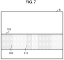
- FIG. 7 is one example of captured image B acquired.
- Road 103 is imaged from an identical point of view in captured image A (see FIG. 5 ) and captured image B.
- Area 610 on road 103 in captured image B is an area identical to the area on road 103 , which corresponds to lowermost point 410 of the tire, in captured image A.
- area 620 on road 103 in captured image B is an area identical to area 420 on road 103 in captured image A.
- Displacement amount detector 262 detects a displacement amount caused between an area on road 103 , which corresponds to lowermost point 410 , in captured image A, and area 610 in captured image B.
- a displacement amount on road 103 caused by an axle load of an ordinary vehicle is very small, it is desirable to suppress an effect of shake of imaging device 101 due to vibration or the like of the vehicle traveling on road 103 .
- displacement amount detector 262 selects, in both captured image A and captured image B, an identical point that is not identified as the axle load position (for example, area 420 in captured image A and area 620 in captured image B).
- displacement amount detector 262 calculates a displacement amount between the selected areas (hereinafter written as a “non-axle load position displacement amount”). Displacement amount detector 262 subtracts this non-axle load position displacement amount from a displacement amount caused between the area on road 103 , which corresponds to lowermost point 410 of the tire, in captured image A, and area 610 in captured image B. Accordingly, displacement amount detector 262 corrects the displacement amount.
- the effect of the shake of imaging device 101 can be suppressed.
- the effect of the shake of imaging device 101 can be also suppressed by a method using an optical image stabilization technology, a method using a mechanical mechanism such as a sensor shift method, or the like.
- axle load calculator 240 identifies a displacement coefficient value corresponding to the axle load position identified by axle load position identifying unit 261 (step S 40 ).
- axle load calculator 240 refers to displacement coefficient ⁇ stored in storage unit 270 (see FIG. 3 ) to identify a displacement coefficient value corresponding to the axle load position identified by axle load position identifying unit 261 .
- axle load calculator 240 multiplies the identified displacement coefficient value by the displacement amount detected by displacement amount detector 262 to calculate an axle load (step S 50 ).
- axle load calculator 240 Upon the calculation of the axle load, axle load calculator 240 outputs a numerical value of the calculated axle load to outside (step S 60 ).
- the numerical value of the calculated axle load is greater than a predetermined reference value
- axle load calculator 240 may notify the user of this situation through notification unit 280 , instead of outputting the numerical value of the calculated axle load to the outside.
- the reference value may be an absolute value or may be a relative value.
- axle load calculator 240 may notify the user of this situation after storing the corresponding captured image. With this configuration, the user can be notified of a relatively high possibility that the vehicle included in the corresponding captured image is overloaded.
- load meter 200 ends the first measurement process.
- the calibration process is a process in which calibrator 250 updates the displacement coefficient stored in storage unit 270 .
- FIG. 4B is a flowchart of the calibration process. This calibration process is started when load meter 200 is activated.
- calibrator 250 inputs a displacement amount every time the displacement amount is detected by displacement amount detector 262 (step S 110 ). Similarly, calibrator 250 inputs an axle number from axle identifying unit 220 (step S 120 ), and inputs a speed from speed calculator 230 (step S 130 ). Calibrator 250 aggregates displacement amounts by associating the detected displacement amount with every condition of the identified axle load position, the axle number, and the speed (step S 140 ).
- calibrator 250 may not generate a histogram of displacement amounts for combinations of all the conditions, and may generate a histogram of displacement amounts for only a limited condition, such as a combination of a specific axle number and a specific speed. It is to be noted that steps S 110 to S 130 may not be provided in this order.
- calibrator 250 aggregates the detected displacement amounts for each local area associated with the displacement coefficient value.
- Load meter 200 repeats the processes in steps S 110 to S 140 until a predetermined condition is satisfied.
- the predetermined condition corresponds to, for example, a case where a predetermined date has come, a case where a predetermined number of displacement amounts is aggregated, or a case where the user performs a predetermined operation to load meter 200 .
- calibrator 250 When the predetermined condition is satisfied in the process in step S 150 (Yes in step S 150 ), calibrator 250 generates a histogram of displacement amounts aggregated in a certain period in the past for each local area based on an obtained aggregation result (step S 160 ).
- FIGS. 8A and 8B is a diagram illustrating one example of the histogram generated by calibrator 250 for each local area.
- vertical axes represent a frequency
- horizontal axes represent a displacement amount.
- the histograms illustrated in FIGS. 8A and 8B are examples of histograms with mutually different aggregation periods and classified by an identical local area, an identical axle number, and an identical speed. A reason that shapes of these histograms are different is that road surface temperatures are mutually different, deterioration states of the road surfaces are mutually different, or the like, in these aggregation periods.
- calibrator 250 Upon the generation of the histogram for each local area, calibrator 250 extracts a characteristic of the histogram (step S 170 ). Then, calibrator 250 calculates a displacement coefficient of the corresponding local area based on the characteristic of the histogram and the second information stored in storage unit 270 . Then, calibrator 250 updates the displacement coefficient stored in storage unit 270 to the calculated displacement coefficient (step S 180 ).
- the characteristic of the histogram indicates a representative value of the displacement amount obtained from the shape of the histogram, such as an average, a mode, a maximum, a minimum, or an average of lower levels with a certain fraction. A case where the mode of the histogram is used as the characteristic of the histogram is described herein as one example.
- Storage unit 270 stores, as the second information, the axle load value of the first axle of the vehicle in which the traffic frequency is expected to be highest in road 103 .
- Calibrator 250 calculates the displacement coefficient by dividing the second information by the mode serving as the representative value of the displacement amount obtained from the shape of the histogram.
- calibrator 250 calculates displacement coefficient ⁇ 1 based on the histogram illustrated in FIG. 8A and the following expression (1).
- ⁇ 1 w 1/ d 1 (1)
- calibrator 250 may calculate the displacement coefficient by using a substitute value instead of the mode. For example, calibrator 250 may use a displacement coefficient in a past time period, or may continuously use the displacement coefficient which has been used before updating the histogram, as the substitute value.
- the histogram of the displacement amounts may have a plurality of frequency peak values.
- calibrator 250 may use an average, a mode, a maximum, or a minimum within a certain range of a displacement amount. With this configuration, a stable characteristic of the histogram can be obtained.
- speed calculator 230 calculates speed v of the vehicle from a movement amount of the vehicle in captured images, in which road 103 is continuously captured in a time-series manner. Also, calibrator 250 may calculate displacement coefficient ⁇ (v) for each speed v. Further, calibrator 250 may update the histogram or calculate the displacement coefficient only when the speed is within a certain range (for example, when speed v of the vehicle ⁇ 20 km/h).
- calibrator 250 after calculating the displacement coefficient, calibrator 250 overwrites the displacement coefficient stored in storage unit 270 by using the calculated displacement coefficient, thereby updating the displacement coefficient (step S 180 ).
- load meter 200 proceeds again to the process in step S 110 , and repeats the processes in step S 110 and subsequent steps.
- calibrator 250 may notify the outside of the need to calibrate the displacement coefficient without automatically updating the displacement coefficient. For example, before step S 180 , calibrator 250 notifies a manager on the outside of the system of the need to calibrate the displacement coefficient by using notification unit 280 through wired or wireless communication. Then, after the manager confirms the notification, calibrator 250 may update the displacement coefficient. Further, load measuring system 1 may function as a system that notifies timing for executing conventional calibration by performing only notification.
- calibration device 300 detects the displacement amount caused by the axle load of vehicle 102 traveling on road 103 from the captured image captured by external imaging device 101 .
- Calibrator 250 generates the histogram of the displacement amounts by aggregating the displacement amounts during the passage of the plurality of vehicles.
- Calibrator 250 can update the displacement coefficient stored in storage unit 270 by using the characteristic of this histogram and the second information about the axle load recorded in storage unit 270 .
- calibrator 250 can automatically implement calibration of load measuring system 1 .
- calibrator 250 can select the axle that can easily obtain a shape characteristic of the histogram by selectively generating the histogram for the axle number. Accordingly, calibration precision improves. Further, calibrator 250 can select the speed that can easily obtain the shape characteristic of the histogram by selectively generating the histogram for the speed of the vehicle. Accordingly, the calibration precision improves.
- calibrator 250 may calculate the displacement coefficient based only on the shape of the histogram corresponding to the first axle (the forefront axle of the vehicle) as the axle number. For example, it is difficult to precisely calculate the axle load of the axle other than the first axle due to an influence of a load placed on a platform of the vehicle. On the other hand, a load of an engine of the vehicle is applied to the axle load of the first axle, and the axle load of the first axle is hardly affected by a weight of the load on the platform of the vehicle. Accordingly, the axle load of the first axle is calculated more precisely than the axle loads of the other axles. Accordingly, calibrator 250 can precisely calculate the displacement coefficient by calculating the displacement coefficient based only on the shape of the histogram corresponding to the first axle.
- calibration device 300 calibrate the displacement coefficient for each position of road 103 .
- multipoint calibration can be easily implemented by automatic calibration. Accordingly, cost and labor for maintenance and management of the measuring system can be reduced.
- calibration device 300 can automatically detect timing to be calibrated. Accordingly, updating work can be performed in a necessary and sufficient frequency.
- the displacement coefficient for calculating the axle load of the vehicle is corrected in the present exemplary embodiment.
- a displacement coefficient for calculating a load of a vehicle may be corrected.
- a load meter previously records a relation between the load of the vehicle and an axle load of the vehicle.
- the load meter can calculate the load of the vehicle by measuring the axle load of the vehicle.
- this load meter generates a histogram of the displacement amounts, and updates the displacement coefficient for calculating the load of the vehicle based on a shape of the histogram.
- the load meter measures the axle load of the vehicle in the present exemplary embodiment.
- the load meter may measure a load of an entire vehicle in an area where the entire vehicle is placed.
- a detector detects displacement amounts at positions of a plurality of axles, and calculates an average of the displacement amounts.
- this load meter generates a histogram of the averages of the displacement amounts, and updates a displacement coefficient for calculating the load of the vehicle based on a shape of the histogram.
- storage unit 270 may record a histogram of loads or axle loads of a vehicle traveling on a road. Moreover, calibrator 250 may update a displacement coefficient based on the shape of the histogram of the displacement amounts and a shape of the histogram of the loads or the axle loads of the vehicle.
- a load meter according to a modified example will be described with reference to FIGS. 8C and 8D . It is to be noted that a load meter according to the modified example has a configuration similar to the configuration of above-described load meter 200 .
- FIG. 8C is a diagram illustrating one example of a histogram of load values acquired in advance. More specifically, the histogram in FIG. 8C is generated by using a calibrated load sensor or load meter. In the present modified example, storage unit 270 stores information indicating this histogram.
- a mode of output values is frequency s 3 .
- the histogram in FIG. 8C has three peak values (frequency s 4 , frequency s 5 , and frequency s 6 ) other than frequency s 3 .
- FIG. 8D is a diagram illustrating one example of a histogram of displacement amounts generated by calibrator 250 .
- the histogram in FIG. 8D is generated from captured images of a road at a position closer to a position of the road in which the above-described load sensor is installed.
- the histogram in FIG. 8C corresponds to the histogram in FIG. 8D .
- a mode of the displacement amounts is frequency d 3 .
- the histogram in FIG. 8D has three peak values (frequency d 4 , frequency d 5 , and frequency d 6 ) other than frequency d 3 .
- frequency s 3 corresponds to frequency d 3 .
- frequency s 4 , frequency s 5 , and frequency s 6 respectively correspond to frequency d 4 , frequency d 5 , and frequency d 6 .
- Calibrator 250 of calibration device 300 in the present modified example updates a displacement coefficient based on shapes of the histogram in FIG. 8C and the histogram in FIG. 8D .
- calibrator 250 calculates the displacement coefficient such that axle load values at frequencies s 3 to s 6 in FIG. 8C substantially coincide with axle load values corresponding to the displacement amounts at frequencies d 3 to d 6 in FIG. 8D , respectively.
- calibrator 250 can update the displacement coefficient by using the highly reliable existing histograms generated by measuring axles of many vehicles. Further, calibrator 250 can calculate the displacement coefficient more precisely by using characteristics of the plurality of histograms (that is, the peak values of the plurality of histograms).
- calibrator 250 may not use frequency s 3 and frequency d 3 serving as the modes.
- a vehicle corresponding to the mode of the histogram is a vehicle having a light axle load.
- frequency s 3 and frequency d 3 serving as the modes easily include many errors. Because of this, calibrator 250 can precisely calculate the displacement coefficient by not using frequency s 3 and frequency d 3 .
- calibrator 250 may update the displacement coefficient based only on a shape of a histogram corresponding to a section that does not include the mode (frequency d 3 ) in the shape of the histogram in FIG. 8D .
- calibrator 250 calculates the displacement coefficient by using the peak values of the histogram.
- calibrator 250 may calculate the displacement coefficient by using other shape characteristics of the histogram.
- calibrator 250 may use a position serving as a valley of the histogram as the shape characteristic of the histogram.
- a load meter according to a second exemplary embodiment configured by modifying a part of the configuration of load meter 200 in the first exemplary embodiment will be described as one aspect of the present disclosure.
- FIG. 9 is a view schematically illustrating one example of a state in which an axle load is measured according to the second exemplary embodiment of the present disclosure.
- load measuring system 2 according to the second exemplary embodiment includes two load sensors 100 and load meter 201 .
- Load meter 200 in the first exemplary embodiment acquires a captured image from imaging device 101 , and calculates a road surface displacement, an axle number, and a speed from this image.
- input unit 211 acquires an output value of load sensor (a strain gauge, a piezoelectric element, or the like) 100 installed in road 103 .
- Load meter 201 detects a displacement amount from the output value of load sensor 100 .
- load sensor a strain gauge, a piezoelectric element, or the like
- FIG. 10 is a block diagram illustrating a configuration of load meter 201 in the second exemplary embodiment.
- load meter 201 includes input unit 211 , axle load calculator 241 , and calibration device 301 .
- Calibration device 301 includes axle identifying unit 221 , speed calculator 231 , calibrator 251 , detector 263 , storage unit 270 , and notification unit 280 .
- load meter 201 is different from load meter 200 (see FIG. 2 ) in the first exemplary embodiment in that input unit 211 acquires the output value of load sensor 100 .
- Axle identifying unit 221 counts a number of axles from a number of changes in the output value of load sensor 100 acquired by input unit 211 accompanied by a passage of a vehicle. If a certain amount of time has passed since the output of load sensor 100 , axle identifying unit 221 judges the passage of the vehicle. Similarly, speed calculator 231 measures the changes in the output value of load sensor 100 acquired by input unit 211 accompanied by the passage of the vehicle. Then, speed calculator 231 calculates a speed of the vehicle by using a passage time between the plurality of load sensors 100 and a known installation distance between load sensors 100 . Instead of the displacement amount in the first exemplary embodiment, calibrator 251 and storage unit 270 each use the output value of load sensor 100 acquired by input unit 211 . Similarly, instead of the displacement amount in the first exemplary embodiment, axle load calculator 241 calculates an axle load by using the output value of load sensor 100 acquired by input unit 211 . Detector 263 calculates a displacement amount from the output value of load sensor 100 .
- Load meter 201 performs, as its characteristic operation, a second measurement process configured by modifying a part of the first measurement process in the first exemplary embodiment.
- the second measurement process is different from the first measurement process in that a procedure of steps S 10 to S 30 in the flowchart of FIG. 4A in the first exemplary embodiment is omitted. Further, the second measurement process is different from the first measurement process in that detector 263 treats an amount of change in the output value of load sensor 100 as a displacement amount. Further, in step S 120 , axle identifying unit 221 identifies an axle number from the number of changes in the output value of load sensor 100 . Further, in step S 130 , speed calculator 231 calculates a speed of the vehicle from a time difference of changes in the output values of the plurality of load sensors 100 and the installation distance between load sensors 100 . The other operation is identical to the operation in the first exemplary embodiment.
- load meter 201 uses the output value obtained by load sensor 100 .
- calibrator 251 aggregates the output values of load sensor 100 accompanied by the passage of ordinary passing vehicles through the operation identical to the operation in the first exemplary embodiment. With this configuration, calibration of load meter 201 can be automatically performed. Accordingly, cost and labor for maintenance and management of the measuring system can be reduced.
- calibration device 301 can automatically judge timing to be calibrated. Accordingly, updating work can be performed in a necessary and sufficient frequency.
- the first and second exemplary embodiments have been described as an illustration of the technique disclosed in the present application.
- the technique in the present disclosure is not limited to those, and can be also applied to exemplary embodiments in which changes, replacements, additions, omissions, or the like are made as appropriate.
- load meter 200 is an example of the configuration provided with input unit 210 receiving an input of a captured image of road 103 captured by imaging device 101 .
- load meter 200 can acquire the captured image
- load meter 200 is not necessarily provided with input unit 210 .
- load meter 200 may include an imaging unit for generating a captured image, instead of including input unit 210 .
- the captured image used by axle load position identifying unit 261 may be a captured image captured by the imaging unit. This configuration eliminates a need of the external imaging device.
- load meter 200 is an example of the configuration implemented in such a way that a microprocessor in a computer provided with the microprocessor and a memory executes a program stored in the memory.
- load meter 200 has a function equivalent to the function in the above-described implementation example
- load meter 200 is not necessarily limited to the configuration example implemented according to the above-described implementation example.
- load meter 200 may be an example of the configuration in which a part of or all of components constituting load meter 200 are implemented by a dedicated circuit.
- load meter 200 is an example of the configuration for recognizing a tire of a vehicle by an image processing and identifying an area on road 103 corresponding to the lowermost point of the tire as an axle load position.
- the method for identifying the axle load position is not necessarily limited to the above-mentioned method.
- load meter 200 may identify a position where a displacement amount locally becomes the maximum as the axle load position.
- axle identifying unit 220 may recognize a vehicle type from the captured image, and calibrator 250 may selectively generate a histogram for a specific vehicle type. A shape characteristic of the histogram can be easily obtained by selecting the vehicle type. Accordingly, the calibration precision improves.
- detector 260 may calculate reliability of the displacement amount from the captured image. Further, calibrator 250 may aggregate the displacement amounts and generate the histogram of the displacement amounts, only when the reliability is higher than a predetermined value. A correlation coefficient, sharpness of distribution of correlation functions, or the like, in case of using a correlation method, can be used as the reliability. The calibration precision is improved by using a highly precise displacement detection result.
- a captured image may be a monochrome image, a color image, or a multispectral image.
- light to be captured in an image may be ultraviolet ray, near infrared ray, or far infrared ray, besides visible light.
- the road surface of road 103 may be, in addition to the asphalt-paved road surface, a road surface formed of another pavement material, such as concrete.
- the road surface of road 103 may be a road surface of the above-described paved road surface partially coated with a plate material, a sheet material, a coating material, or the like.
- the road surface of road 103 may be coated with one of the above-mentioned materials, and the coated area may be defined as an area from which displacement is to be detected.
- the components (function blocks) in load meters 200 , 201 may be individually implemented as single chips, or a single chip may include a part of or all of the components, by means of a semiconductor device, such as an integrated circuit (IC) or large scale integration (LSI).
- IC integrated circuit
- LSI large scale integration
- the method of implementing integrated circuitry is not limited to the LSI, and implementation may be achieved by means of dedicated circuitry or a general-purpose processor.
- a field programmable gate array (FPGA) for which programming is possible after LSI fabrication, or a reconfigurable processor allowing reconfiguration of connections and settings of circuit cells within an LSI, may also be used in implementing integrated circuitry.
- FPGA field programmable gate array
- the function blocks may be integrated by using that technique. For example, application of biotechnology is possible.
- All of or a part of various processes described above may be implemented by a hardware product such as an electronic circuit, or may be implemented by using software. It is to be noted that the process using software is implemented in such a way that the processor in the load meter executes the program stored in the memory. Furthermore, the program may be recorded in a recording medium and may be distributed or circulated. For example, the distributed program is installed in another device including a processor, and the program is executed by the processor. In this way, the device can execute the above-described processes.
- the calibration device according to the present disclosure is widely applicable to a load meter for measuring an axle load.
Abstract
Description
α1=w1/d1 (1)
α2=w1/d2 (2)
-
- 1, 2: load measuring system
- 100: load sensor
- 101: imaging device
- 102: vehicle
- 103: road
- 200, 201: load meter
- 210, 211: input unit
- 220, 221: axle identifying unit
- 230, 231: speed calculator
- 240, 241: axle load calculator
- 250, 251: calibrator
- 260, 263: detector
- 261: axle load position identifying unit
- 262: displacement amount detector
- 270: storage unit
- 280: notification unit
- 300, 301: calibration device
Claims (11)
Applications Claiming Priority (3)
| Application Number | Priority Date | Filing Date | Title |
|---|---|---|---|
| JP2017-036228 | 2017-02-28 | ||
| JP2017036228 | 2017-02-28 | ||
| PCT/JP2017/023012 WO2018158971A1 (en) | 2017-02-28 | 2017-06-22 | Calibration device and calibration method |
Related Parent Applications (1)
| Application Number | Title | Priority Date | Filing Date |
|---|---|---|---|
| PCT/JP2017/023012 Continuation WO2018158971A1 (en) | 2017-02-28 | 2017-06-22 | Calibration device and calibration method |
Publications (2)
| Publication Number | Publication Date |
|---|---|
| US20180245969A1 US20180245969A1 (en) | 2018-08-30 |
| US10697821B2 true US10697821B2 (en) | 2020-06-30 |
Family
ID=61158272
Family Applications (1)
| Application Number | Title | Priority Date | Filing Date |
|---|---|---|---|
| US15/886,891 Active 2037-12-10 US10697821B2 (en) | 2017-02-28 | 2018-02-02 | Weight calibration for a vehicle weight load determination meter |
Country Status (2)
| Country | Link |
|---|---|
| US (1) | US10697821B2 (en) |
| JP (1) | JP6273502B1 (en) |
Families Citing this family (3)
| Publication number | Priority date | Publication date | Assignee | Title |
|---|---|---|---|---|
| EP3591355B1 (en) * | 2017-02-28 | 2022-03-02 | Panasonic Intellectual Property Management Co., Ltd. | Load meter, and load measurement method |
| JP2019163971A (en) * | 2018-03-19 | 2019-09-26 | 株式会社イシダ | Commodity inspection system |
| WO2020179188A1 (en) | 2019-03-01 | 2020-09-10 | 日本電気株式会社 | Device for measuring displacement in structural object |
Citations (21)
| Publication number | Priority date | Publication date | Assignee | Title |
|---|---|---|---|---|
| JPS5034268A (en) | 1973-07-26 | 1975-04-02 | ||
| US4813004A (en) * | 1986-04-28 | 1989-03-14 | Kabushiki Kaisha Toshiba | Method for measuring the maximum gross weight of a motor vehicle |
| JPH04328427A (en) * | 1991-04-27 | 1992-11-17 | Kyowa Electron Instr Co Ltd | Testing apparatus for inspecting stationary axle load meter |
| JPH0618319A (en) | 1992-06-30 | 1994-01-25 | Shimadzu Corp | Electronic balance |
| JPH08293090A (en) | 1995-02-23 | 1996-11-05 | Omron Corp | Axle detector, body kind discriminating device, vehicle gate system, and vehicle detector |
| US6552278B2 (en) * | 2001-09-10 | 2003-04-22 | Weigh-Tronix Inc. | Multiple load sensing multi-load cell scale and method |
| JP2005030786A (en) | 2003-07-07 | 2005-02-03 | Mitsubishi Heavy Ind Ltd | Method for measuring axle load and weight of bridge passing vehicle, and its device |
| JP2005061984A (en) | 2003-08-12 | 2005-03-10 | Hitachi Constr Mach Co Ltd | Load measuring apparatus of construction equipment |
| US20060137914A1 (en) * | 2004-12-23 | 2006-06-29 | Osmos S.A. | Method and device for measuring the weight applied to the ground by at least one axle |
| EP1927827A2 (en) | 2006-12-01 | 2008-06-04 | Mitsubishi Heavy Industries, Ltd. | System for determining vehicle axle overload |
| JP2009168715A (en) | 2008-01-18 | 2009-07-30 | Hitachi Ltd | Vehicle weight estimation system |
| JP2010261825A (en) | 2009-05-08 | 2010-11-18 | Omron Corp | Weight-measuring device of traveling vehicle, and sensitivity correction method for weight sensor |
| US20110267200A1 (en) * | 2010-04-29 | 2011-11-03 | Reynolds William R | Weigh-in-motion scale |
| US8165775B2 (en) * | 2007-08-03 | 2012-04-24 | Nissan Motor Co., Ltd. | System and method for controlling running of a vehicle |
| US20120160574A1 (en) * | 2009-09-28 | 2012-06-28 | Kabushiki Kaisha Toshiba | Vehicle passage tread sensor and vehicle passage detection apparatus |
| US20130070086A1 (en) * | 2010-03-29 | 2013-03-21 | Robert Bosch Gmbh | Method for Controlling a Measuring System and Measuring System for Implementing the Method |
| WO2016047093A1 (en) | 2014-09-25 | 2016-03-31 | 日本電気株式会社 | Status determination device and status determination method |
| US20160187183A1 (en) * | 2012-05-16 | 2016-06-30 | Kistler Holding Ag | Sensor module of a wim system and mesurement method |
| JP2017058177A (en) | 2015-09-15 | 2017-03-23 | 学校法人五島育英会 | Measurement device, measurement method, program, and measurement system |
| US20170234722A1 (en) * | 2016-02-17 | 2017-08-17 | Right Weigh, Inc. | Automatic calibration of on-vehicle weight scales |
| US20180274966A1 (en) * | 2015-09-18 | 2018-09-27 | Cross Zlín, A.S. | Weight measuring device and the measuring method |
Family Cites Families (3)
| Publication number | Priority date | Publication date | Assignee | Title |
|---|---|---|---|---|
| JP3702238B2 (en) * | 2002-03-18 | 2005-10-05 | 三菱重工業株式会社 | Vehicle weight measuring method, vehicle axle weight measuring system, and overloaded vehicle warning system |
| CH702963A1 (en) * | 2010-04-01 | 2011-10-14 | Kistler Holding Ag | Method for calibration of sensors wim. |
| US9121751B2 (en) * | 2011-11-15 | 2015-09-01 | Cognex Corporation | Weighing platform with computer-vision tracking |
-
2017
- 2017-06-22 JP JP2017551721A patent/JP6273502B1/en active Active
-
2018
- 2018-02-02 US US15/886,891 patent/US10697821B2/en active Active
Patent Citations (22)
| Publication number | Priority date | Publication date | Assignee | Title |
|---|---|---|---|---|
| JPS5034268A (en) | 1973-07-26 | 1975-04-02 | ||
| US4813004A (en) * | 1986-04-28 | 1989-03-14 | Kabushiki Kaisha Toshiba | Method for measuring the maximum gross weight of a motor vehicle |
| JPH04328427A (en) * | 1991-04-27 | 1992-11-17 | Kyowa Electron Instr Co Ltd | Testing apparatus for inspecting stationary axle load meter |
| JPH0618319A (en) | 1992-06-30 | 1994-01-25 | Shimadzu Corp | Electronic balance |
| JPH08293090A (en) | 1995-02-23 | 1996-11-05 | Omron Corp | Axle detector, body kind discriminating device, vehicle gate system, and vehicle detector |
| US6552278B2 (en) * | 2001-09-10 | 2003-04-22 | Weigh-Tronix Inc. | Multiple load sensing multi-load cell scale and method |
| JP2005030786A (en) | 2003-07-07 | 2005-02-03 | Mitsubishi Heavy Ind Ltd | Method for measuring axle load and weight of bridge passing vehicle, and its device |
| JP2005061984A (en) | 2003-08-12 | 2005-03-10 | Hitachi Constr Mach Co Ltd | Load measuring apparatus of construction equipment |
| US20060137914A1 (en) * | 2004-12-23 | 2006-06-29 | Osmos S.A. | Method and device for measuring the weight applied to the ground by at least one axle |
| EP1927827A2 (en) | 2006-12-01 | 2008-06-04 | Mitsubishi Heavy Industries, Ltd. | System for determining vehicle axle overload |
| US8165775B2 (en) * | 2007-08-03 | 2012-04-24 | Nissan Motor Co., Ltd. | System and method for controlling running of a vehicle |
| JP2009168715A (en) | 2008-01-18 | 2009-07-30 | Hitachi Ltd | Vehicle weight estimation system |
| JP2010261825A (en) | 2009-05-08 | 2010-11-18 | Omron Corp | Weight-measuring device of traveling vehicle, and sensitivity correction method for weight sensor |
| US20120160574A1 (en) * | 2009-09-28 | 2012-06-28 | Kabushiki Kaisha Toshiba | Vehicle passage tread sensor and vehicle passage detection apparatus |
| US20130070086A1 (en) * | 2010-03-29 | 2013-03-21 | Robert Bosch Gmbh | Method for Controlling a Measuring System and Measuring System for Implementing the Method |
| US20110267200A1 (en) * | 2010-04-29 | 2011-11-03 | Reynolds William R | Weigh-in-motion scale |
| US20160187183A1 (en) * | 2012-05-16 | 2016-06-30 | Kistler Holding Ag | Sensor module of a wim system and mesurement method |
| WO2016047093A1 (en) | 2014-09-25 | 2016-03-31 | 日本電気株式会社 | Status determination device and status determination method |
| US20170307360A1 (en) | 2014-09-25 | 2017-10-26 | Nec Corporation | Status determination device and status determination method |
| JP2017058177A (en) | 2015-09-15 | 2017-03-23 | 学校法人五島育英会 | Measurement device, measurement method, program, and measurement system |
| US20180274966A1 (en) * | 2015-09-18 | 2018-09-27 | Cross Zlín, A.S. | Weight measuring device and the measuring method |
| US20170234722A1 (en) * | 2016-02-17 | 2017-08-17 | Right Weigh, Inc. | Automatic calibration of on-vehicle weight scales |
Non-Patent Citations (6)
| Title |
|---|
| Extended European Search Report dated Mar. 3, 2020 in corresponding European Patent Application No. 18760961.5. |
| International Search Report and Written Opinion dated Mar. 27, 2018 in International Application No. PCT/JP2018/001120. |
| International Search Report of PCT application No. PCT/JP2017/023012 dated Aug. 22, 2017. |
| Translation JP-04328427 (Year: 1992). * |
| Translation JP-2009168715 (Year: 2009). * |
| Translation JP-2010261825 (Year: 2010). * |
Also Published As
| Publication number | Publication date |
|---|---|
| JPWO2018158971A1 (en) | 2019-03-07 |
| JP6273502B1 (en) | 2018-02-07 |
| US20180245969A1 (en) | 2018-08-30 |
Similar Documents
| Publication | Publication Date | Title |
|---|---|---|
| US11536602B2 (en) | Load meter and load measurement method | |
| US10473515B2 (en) | Weight measuring device, weight measurement method, displacement coefficient calculating device, and displacement coefficient calculation method | |
| US10982951B2 (en) | Axle-load measuring apparatus and axle-load measuring method | |
| US20230079730A1 (en) | Control device, scanning system, control method, and program | |
| US10697821B2 (en) | Weight calibration for a vehicle weight load determination meter | |
| US20120224069A1 (en) | Calibration apparatus, a distance measurement system, a calibration method and a calibration program | |
| US10982993B2 (en) | Overload detection processing apparatus, overload detection system and computer-readable recording medium storing program | |
| EP2902967B1 (en) | Stereo camera calibration method, disparity calculating device, and stereo camera | |
| WO2015133414A1 (en) | Calibrarion method, calibration device, and computer program product | |
| JP6899518B2 (en) | Load measuring device, load measuring method, load measuring program, displacement coefficient calculation device, displacement coefficient calculation method, and displacement coefficient calculation program | |
| US10609292B2 (en) | Imaging apparatus, axle load measuring system, and imaging method | |
| US20160207473A1 (en) | Method of calibrating an image detecting device for an automated vehicle | |
| US10914572B2 (en) | Displacement measuring apparatus and displacement measuring method | |
| CN111868486B (en) | Axle load measuring device and axle load measuring method | |
| EP3624064A1 (en) | Vehicle-mounted environment recognition device | |
| EP3591353B1 (en) | Calibration device and calibration method | |
| US11175175B2 (en) | Dual tire determination device and dual tire determination method | |
| JP6890258B2 (en) | Calibration equipment and calibration method | |
| JP3775680B2 (en) | Method for measuring the shape of the object to be measured |
Legal Events
| Date | Code | Title | Description |
|---|---|---|---|
| FEPP | Fee payment procedure |
Free format text: ENTITY STATUS SET TO UNDISCOUNTED (ORIGINAL EVENT CODE: BIG.); ENTITY STATUS OF PATENT OWNER: LARGE ENTITY |
|
| AS | Assignment |
Owner name: PANASONIC INTELLECTUAL PROPERTY MANAGEMENT CO., LTD., JAPAN Free format text: ASSIGNMENT OF ASSIGNORS INTEREST;ASSIGNORS:IMAGAWA, TARO;NODA, AKIHIRO;KUSAKA, HIROYA;REEL/FRAME:045594/0562 Effective date: 20180109 Owner name: PANASONIC INTELLECTUAL PROPERTY MANAGEMENT CO., LT Free format text: ASSIGNMENT OF ASSIGNORS INTEREST;ASSIGNORS:IMAGAWA, TARO;NODA, AKIHIRO;KUSAKA, HIROYA;REEL/FRAME:045594/0562 Effective date: 20180109 |
|
| STPP | Information on status: patent application and granting procedure in general |
Free format text: DOCKETED NEW CASE - READY FOR EXAMINATION |
|
| STPP | Information on status: patent application and granting procedure in general |
Free format text: NON FINAL ACTION MAILED |
|
| STPP | Information on status: patent application and granting procedure in general |
Free format text: RESPONSE TO NON-FINAL OFFICE ACTION ENTERED AND FORWARDED TO EXAMINER |
|
| STPP | Information on status: patent application and granting procedure in general |
Free format text: NOTICE OF ALLOWANCE MAILED -- APPLICATION RECEIVED IN OFFICE OF PUBLICATIONS |
|
| STPP | Information on status: patent application and granting procedure in general |
Free format text: NOTICE OF ALLOWANCE MAILED -- APPLICATION RECEIVED IN OFFICE OF PUBLICATIONS |
|
| STPP | Information on status: patent application and granting procedure in general |
Free format text: PUBLICATIONS -- ISSUE FEE PAYMENT RECEIVED |
|
| STCF | Information on status: patent grant |
Free format text: PATENTED CASE |
|
| MAFP | Maintenance fee payment |
Free format text: PAYMENT OF MAINTENANCE FEE, 4TH YEAR, LARGE ENTITY (ORIGINAL EVENT CODE: M1551); ENTITY STATUS OF PATENT OWNER: LARGE ENTITY Year of fee payment: 4 |