US10697597B2 - Housing, connector and system - Google Patents
Housing, connector and system Download PDFInfo
- Publication number
- US10697597B2 US10697597B2 US15/390,104 US201615390104A US10697597B2 US 10697597 B2 US10697597 B2 US 10697597B2 US 201615390104 A US201615390104 A US 201615390104A US 10697597 B2 US10697597 B2 US 10697597B2
- Authority
- US
- United States
- Prior art keywords
- engagement portion
- housing
- freedom
- latching
- engagement
- Prior art date
- Legal status (The legal status is an assumption and is not a legal conclusion. Google has not performed a legal analysis and makes no representation as to the accuracy of the status listed.)
- Active, expires
Links
- 239000011159 matrix material Substances 0.000 description 18
- 235000001674 Agaricus brunnescens Nutrition 0.000 description 3
- 230000008901 benefit Effects 0.000 description 3
- 230000008878 coupling Effects 0.000 description 3
- 238000010168 coupling process Methods 0.000 description 3
- 238000005859 coupling reaction Methods 0.000 description 3
- 230000007246 mechanism Effects 0.000 description 3
- 238000000034 method Methods 0.000 description 2
- 230000008569 process Effects 0.000 description 2
- 230000000694 effects Effects 0.000 description 1
- 238000001125 extrusion Methods 0.000 description 1
- 238000009434 installation Methods 0.000 description 1
- 238000012986 modification Methods 0.000 description 1
- 230000004048 modification Effects 0.000 description 1
Images


Classifications
-
- F—MECHANICAL ENGINEERING; LIGHTING; HEATING; WEAPONS; BLASTING
- F21—LIGHTING
- F21S—NON-PORTABLE LIGHTING DEVICES; SYSTEMS THEREOF; VEHICLE LIGHTING DEVICES SPECIALLY ADAPTED FOR VEHICLE EXTERIORS
- F21S2/00—Systems of lighting devices, not provided for in main groups F21S4/00 - F21S10/00 or F21S19/00, e.g. of modular construction
- F21S2/005—Systems of lighting devices, not provided for in main groups F21S4/00 - F21S10/00 or F21S19/00, e.g. of modular construction of modular construction
-
- F—MECHANICAL ENGINEERING; LIGHTING; HEATING; WEAPONS; BLASTING
- F21—LIGHTING
- F21V—FUNCTIONAL FEATURES OR DETAILS OF LIGHTING DEVICES OR SYSTEMS THEREOF; STRUCTURAL COMBINATIONS OF LIGHTING DEVICES WITH OTHER ARTICLES, NOT OTHERWISE PROVIDED FOR
- F21V15/00—Protecting lighting devices from damage
- F21V15/01—Housings, e.g. material or assembling of housing parts
-
- F—MECHANICAL ENGINEERING; LIGHTING; HEATING; WEAPONS; BLASTING
- F21—LIGHTING
- F21V—FUNCTIONAL FEATURES OR DETAILS OF LIGHTING DEVICES OR SYSTEMS THEREOF; STRUCTURAL COMBINATIONS OF LIGHTING DEVICES WITH OTHER ARTICLES, NOT OTHERWISE PROVIDED FOR
- F21V21/00—Supporting, suspending, or attaching arrangements for lighting devices; Hand grips
- F21V21/08—Devices for easy attachment to any desired place, e.g. clip, clamp, magnet
- F21V21/088—Clips; Clamps
-
- F—MECHANICAL ENGINEERING; LIGHTING; HEATING; WEAPONS; BLASTING
- F21—LIGHTING
- F21V—FUNCTIONAL FEATURES OR DETAILS OF LIGHTING DEVICES OR SYSTEMS THEREOF; STRUCTURAL COMBINATIONS OF LIGHTING DEVICES WITH OTHER ARTICLES, NOT OTHERWISE PROVIDED FOR
- F21V21/00—Supporting, suspending, or attaching arrangements for lighting devices; Hand grips
- F21V21/14—Adjustable mountings
- F21V21/26—Pivoted arms
-
- F—MECHANICAL ENGINEERING; LIGHTING; HEATING; WEAPONS; BLASTING
- F21—LIGHTING
- F21Y—INDEXING SCHEME ASSOCIATED WITH SUBCLASSES F21K, F21L, F21S and F21V, RELATING TO THE FORM OR THE KIND OF THE LIGHT SOURCES OR OF THE COLOUR OF THE LIGHT EMITTED
- F21Y2115/00—Light-generating elements of semiconductor light sources
- F21Y2115/10—Light-emitting diodes [LED]
Definitions
- Embodiments of the present invention relate to a housing for a lighting apparatus, to a connector for the housing, and to a system. Further embodiments relate to a system comprising a plurality of lighting apparatuses which are connected to one another by means of connectors to form a matrix.
- lighting apparatuses comprise a housing which may be mounted to a cross-beam or another mounting point by means of a bracket. Further lighting apparatuses may also be integrated in a housing such that the housing accommodates several lighting apparatuses. Such a unit may also be referred to as spot unit, wherein said spot unit may typically also be mounted using a kind of bracket.
- the illuminator chooses either one or several individual lighting apparatuses or a lighting unit for the respective lighting situation, depending on how much lighting is required. If the lighting unit provides for too much lighting and the individual lighting apparatus allows only too little lighting, several lighting apparatuses may be arranged next to one another in order to scale the lighting. However, these lighting apparatuses have to be oriented individually to the area to be illuminated, thereby increasing the complexity for installation. Therefore, there is demand for an improved approach.
- a housing of a lighting apparatus may have: at least two first engagement portions at two different sides of the housing; wherein each first engagement portion is suitable for being connectable to a second engagement portion of a connector by translatory pushing into each other such that the housing is restricted relative to the connector in two degrees of freedom in a translatory respect and in three degrees of freedom in a rotary respect; wherein the at least two first engagement portions are each formed by a plate spaced apart from the housing and/or a slot nut; wherein the first engagement portion has means for latching suitable for allowing engagement of the means for latching of the second engagement portion in the first engagement portion so that the housing is restricted relative to the connector in a third degree of freedom in a translatory respect; wherein the means for latching of the first engagement portion have a spring element which is movable transverse to the third degree of freedom; and wherein the means for latching of the second engagement portion have a recess transverse to the third degree of freedom, in which the spring element may engage; or wherein the means for
- a connector for connecting a housing of a lighting apparatus may have: at least one second engagement portion for the housing; and a further engagement portion for an element coupled to the housing; wherein first engagement portions of the housing are each formed by a plate spaced apart from the housing and/or a slot nut; wherein every second engagement portion is connectable to a first engagement portion of the housing by translatory pushing into each other such that the housing is restricted relative to the connector in two degrees of freedom in a translatory respect and in three degrees of freedom in a rotary respect; wherein the first engagement portion has means for latching suitable for allowing engagement of the means for latching of the second engagement portion in the first engagement portion so that the housing is restricted relative to the connector in a third degree of freedom in a translatory respect; wherein the means for latching of the first engagement portion have a spring element which is movable transverse to the third degree of freedom; and wherein the means for latching of the second engagement portion have a recess transverse to the third degree of freedom, in which the spring
- a system may have: a housing a mentioned above; and a connector for connecting a housing of a lighting apparatus, having: at least one second engagement portion for the housing; and a further engagement portion for an element coupled to the housing; wherein first engagement portions of the housing are each formed by a plate spaced apart from the housing and/or a slot nut; wherein every second engagement portion is connectable to a first engagement portion of the housing by translatory pushing into each other such that the housing is restricted relative to the connector in two degrees of freedom in a translatory respect and in three degrees of freedom in a rotary respect; wherein the first engagement portion has means for latching suitable for allowing engagement of the means for latching of the second engagement portion in the first engagement portion so that the housing is restricted relative to the connector in a third degree of freedom in a translatory respect; wherein the means for latching of the first engagement portion have a spring element which is movable transverse to the third degree of freedom; and wherein the means for latching of the second engagement portion have a rece
- a system may have: a housing as mentioned above; two connectors for connecting a housing of a lighting apparatus, having: at least one second engagement portion for the housing; and a further engagement portion for an element coupled to the housing; wherein first engagement portions of the housing are each formed by a plate spaced apart from the housing and/or a slot nut; wherein every second engagement portion is connectable to a first engagement portion of the housing by translatory pushing into each other such that the housing is restricted relative to the connector in two degrees of freedom in a translatory respect and in three degrees of freedom in a rotary respect; wherein the first engagement portion has means for latching suitable for allowing engagement of the means for latching of the second engagement portion in the first engagement portion so that the housing is restricted relative to the connector in a third degree of freedom in a translatory respect; wherein the means for latching of the first engagement portion have a spring element which is movable transverse to the third degree of freedom; and wherein the means for latching of the second engagement portion have a recess
- a system may have: at least two housings as mentioned above; and at least one connector for connecting a housing of a lighting apparatus, having: at least one second engagement portion for the housing; and a further engagement portion for an element coupled to the housing; wherein first engagement portions of the housing are each formed by a plate spaced apart from the housing and/or a slot nut; wherein every second engagement portion is connectable to a first engagement portion of the housing by translatory pushing into each other such that the housing is restricted relative to the connector in two degrees of freedom in a translatory respect and in three degrees of freedom in a rotary respect; wherein the first engagement portion has means for latching suitable for allowing engagement of the means for latching of the second engagement portion in the first engagement portion so that the housing is restricted relative to the connector in a third degree of freedom in a translatory respect; wherein the means for latching of the first engagement portion have a spring element which is movable transverse to the third degree of freedom; and wherein the means for latching of the second engagement portion have
- Embodiments of the present invention provide a housing of a lighting apparatus, comprising at least two first engagement portions at two different sides of the housing.
- Each first engagement portion may be connected to a second engagement portion of a connector by means of translatory pushing into one another such that the housing is restricted relative to the connector in two degrees of freedom in a translatory respect and in three degrees of freedom in a rotatory respect.
- the first engagement portion comprises means for latching suitable for allowing engagement of means for latching of the second engagement portion in the first engagement portion so that the housing is restricted relative to the connector in a third degree of freedom in a translatory respect.
- the central idea of the present invention is having recognized that a freely scalable concept is provided by a first flange (first engagement portion) at the housing in combination with a second flange (second engagement portion) of a connector, the second flange forming the counterpart to the first flange, by the connector comprising a further engagement portion or further flange for either a retainer or for a further housing.
- a freely scalable lighting unit lighting matrix
- the work of orienting the individual lighting apparatuses may be omitted since the orientation of the lighting apparatuses among one another is fixed already by the geometry of the connector.
- Such connectors which allow a parallel orientation of the lighting apparatuses or an angled orientation, like an orientation angled by 45°, are possible direct connectors.
- the first engagement portion extends as a first rail along a longitudinal axis such that the rail comprises a first profile which also extends along the longitudinal axis.
- the second engagement portion which, as has been described above, forms the counterpart, also extends along the longitudinal axis as a second rail.
- the second rail comprises a second profile extending along the longitudinal axis.
- either the first or the second profile comprises an undercutting into which the other profile may be pushed along the longitudinal axis.
- Such a connection provides a simple, but mechanically stable mechanism which restricts the five degrees of freedom mentioned before of the two elements to be connected (lighting and connector).
- these engagement portions of the housing are arranged at two opposite sides of the housing so that one connector may be coupled to each side and these two connectors are additionally connected to a two-sided retaining bracket in order to mount the lighting apparatus to a further element, like a cross-beam.
- the two-sided retaining bracket may be implemented as a so-called double bracket which serves as a foot when folded out and, when folded in, as a conventional bracket by means of which the lighting apparatus may, for example, be mounted to a cross-beam.
- a connector comprising at least one second engagement portion for the housing and a further engagement portion for a retainer for the housing.
- a simple clamp may be provided as a retainer so that the lighting apparatus may also be mounted only on one side relative to the further element/cross-beam.
- embodiments provide a system comprising at least one housing, as discussed above, and a connector for coupling a retainer.
- the system may also comprise the corresponding retainer.
- the retainer is a one-sided or a two-sided retainer
- the system comprises the clamp in combination with a bracket, or double bracket. In the case of the bracket or double bracket, the system typically comprises two equal connectors.
- the connector may also comprise a second engagement portion instead of or as a further engagement portion so that the connector connects two housings of lighting apparatuses to each other.
- the lighting apparatus it is of advantage here for the lighting apparatus to comprise two or, advantageously, four first engagement portions at four different sides (that is arranged at 90° relative to one another, for example), since in this way the lighting apparatuses may be arranged to form a matrix or, generally, a two-dimensional arrangement using the connectors.
- Further embodiments provide a system comprising at least two of the housings discussed before and an interconnector. This system may be extended by further embodiments by connectors for coupling a retainer so that the lighting unit provided by means of the interconnectors may be mounted to an external element, for example a cross-beam.
- Embodiments provide a system comprising at least three, but advantageously more than three housings of a lighting apparatus which are connected to one another by at least two, but preferably more interconnectors so as to form a flat lighting matrix. This means that a two-dimensional flat and freely scalable lighting element is provided.
- Another embodiment relates to the interconnector which comprises C-shaped openings, for example, so that it can couple the two housings which comprise the counterpart, that is the slot nut or the plate having the undercut.
- FIG. 1 a - 1 , FIG. 1 a - 2 and FIG. 1 a - 3 shows five schematic lateral views of a lighting apparatus housing in combination with two connectors and at least one bracket as a retainer, wherein in this embodiment the retainer is implemented as a foot;
- FIG. 1 b - 1 and FIG. 1 b - 2 shows six schematic lateral views of the embodiment of FIG. 1 a - 1 , FIG. 1 a - 2 and FIG. 1 a - 3 for illustrating the range of movement of the housing relative to the retainer;
- FIG. 2A , FIG. 2B , and FIG. 2C shows four schematic lateral views of a housing of a lighting apparatus in combination with two connectors and a bracket and a clamp for mounting the lighting apparatus to a cross-beam in accordance with embodiments;
- FIG. 3 a - 1 , FIG. 3 a - 2 , FIG. 3 b - 1 , and FIG. 3 b - 2 each show four schematic lateral views when pushing the connector into the engagement portion of the lighting apparatus housing, with respective enlarged illustrations, wherein in this embodiment the connector is an interconnector;
- FIG. 4 a - 1 , FIG. 4 a - 2 , FIG. 4 b - 1 , and FIG. 4 b - 2 show schematic illustrations of lighting apparatuses positioned in a matrix arrangement which are connected to one another by means of interconnectors in accordance with embodiments;
- FIG. 5 a , FIG. 5 b , and FIG. 5 c show connections comprising first and second engagement portions with and without undercutting in accordance with embodiments.
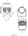
- FIG. 1 a - 1 , FIG. 1 a - 2 and FIG. 1 a - 3 shows a lighting apparatus 1 comprising a housing 10 g , wherein the housing 10 is arranged to be cuboid and comprises a lighting opening 10 o on one side.
- This lighting opening 10 o is arranged on the front part of the housing 10 g , wherein the mounting receptacles are provided on the back part of the housing 10 g.
- the mounting receptacles are implemented as at least two engagement portions 10 e .
- the round or cuboid lighting apparatus 1 comprises four basically perpendicular side faces, in this embodiment—instead of at least two—four optional engagement portions 10 e are provided which are provided with the reference numerals 10 e _ 1 , 10 e _ 2 , 10 e _ 3 and 10 e _ 4 .
- the engagement portions 10 e _ 1 to 10 e _ 4 are exemplarily based on the undercutting principle. This allows fitting the coupled connectors 12 _ 1 and 12 _ 3 into each other by means of pushing along a longitudinal axis 10 l of the housing 10 .
- These inserted connections are of advantage in that plugging is considerably less complicated for a fitter compared to conventional screwing.
- the realization (used here) of dove tail guides of the engagement portions 10 e _l to 10 e _ 4 is particularly clear in the front view and back view of the spotlight housing 10 .
- the engagement portion 10 e _ 2 comprises such a profile that the foot of the profile, that is that part facing the housing 10 g , is narrower than the head of the engagement portion.
- the connector (cf. connector 12 e _ 3 ) also comprises a profile as a second engagement portion 12 e _ 3 which, after pushing in, surrounds the profile of the engagement portion 10 e _ 3 .
- the result is that the degree of freedom may be restricted by such a connection in two longitudinal directions (that is in all except for the direction 10 l ), and in all rotary directions.
- the engagement portion 10 e _ 1 and 10 e _ 3 comprises a plate which is spaced apart from the actual housing 10 so that the second engagement portion 12 e _ 1 and 12 e _ 2 which exemplarily comprises a C profile engage below said plate when pushed in and thus forms the connection—while restricting the degrees of freedom in two translatory directions and in the three rotary directions.
- Different types of these connections will be discussed referring to FIGS. 5 a to 5 c.
- the connectors 12 _ 1 and 12 _ 3 are each provided at two opposite sides of the housing 10 g .
- the connectors 12 _ 1 and 12 _ 3 comprise, as has been discussed already, a second engagement portion 12 e _ 3 and 12 e _ 1 , respectively, on the one side, whereas a further engagement portion 12 w _ 1 and 12 w _ 3 , respectively, is provided on a second side. Due to the fact that the two interconnectors 12 _ 3 and 12 _ 1 are inserted or arranged at opposite sides of the housing 10 , the further engagement portions 12 w _ 3 and 12 w _l are each directed in mutually opposite directions.
- An optional bracket 14 which is mounted to be pivotable relative to the connectors 12 _ 3 , 12 _ 1 is then mounted via these further engagement portions 12 w _ 3 and 12 w _ 1 .
- This bracket 14 comprises two 90° angles so that it clutches the lighting apparatus 10 .
- This bracket 14 allows the lighting apparatus 1 to be pivotable relative to the bracket 14 and, thus, also relative to a support of fixed location.
- a knurled screw 14 r screwed into one of interconnectors 12 _ 1 and guided within a slot 14 n of the bracket may be provided for locking the pivot mechanism. It is to be pointed out here that the knurled screw 14 r or, generally, the locking mechanism may also be implemented in different ways.
- FIG. 1 b - 1 and FIG. 1 b - 2 The range of movement of the spotlight 1 relative to the bracket 14 is illustrated in FIG. 1 b - 1 and FIG. 1 b - 2 , wherein it is assumed that the bracket 14 is not screwed to a cross-beam, but serves as a foot.
- FIG. 1 b - 1 and FIG. 1 b - 2 two lighting apparatuses oriented in different directions are illustrated, wherein a housing directed upwards is provided with the reference numeral 10 ′, whereas a housing directed laterally has the reference numeral 10 ′′.
- the lighting apparatus housing 10 ′ and 10 ′′ may be rotated by 270° or more around the point or axis of rotation 14 _ d 1 .
- the bracket may also be implemented as a so-called double bracket.
- This double bracket comprises the two elements 14 a and 14 b (each brackets) which are movable relative to each other around the point of rotation 14 d 2 .
- a first and a second relative position between the brackets 14 a and 14 b may be implemented by the guide 14 f and the bolt 14 b .
- the two brackets 14 a and 14 b are angled relative to each other, for example, arranged to be at an angle of 90°, and thus form a foot.
- the two brackets 14 a and 14 b (cf. FIG. 2A , FIG. 2B and FIG. 2C ) are folded in and thus parallel, which allows the bracket 14 to be usable as a conventional retaining bracket.
- connecters illustrated may, as is discussed referring to FIG. 3 a - 1 , FIG. 3 a - 2 , FIG. 3 b i 1 , and FIG. 3 b - 2 , also be equipped with means for latching 10 r and 22 r or latching means so that forces along the third longitudinal axis Z/ 10 l (cf. FIGS. 3 a , 3 b ) may be supported.
- FIGS. 3 a , 3 b latching means
- a spring element 22 r (bolt or ball) which is movable transverse to the third degree of freedom Z on the side of the second engagement portion 12 e _ 1 and 12 e _ 2 10 e _ 1 , wherein the means for latching the first engagement portion 10 e _ 2 , 10 e _ 3 and 10 e _ 4 comprise a recess 10 r transverse to the third degree of freedom Z which the spring element may engage in.
- the means for latching the first engagement portion 10 e _ 1 , 10 e _ 2 , 10 e _ 3 and 10 e _ 4 may comprise the spring element which is movable transverse to the third degree of freedom Z, wherein the means for latching the second engagement portion 12 e _ 1 and 12 e _ 2 comprise a recess transverse to the third degree of freedom Z which the spring element may engage in.
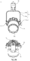
- FIG. 2A , FIG. 2B , and FIG. 2C shows the housing 10 of the lighting apparatus 1 in combination with the two connectors 12 _ 1 and 12 _ 3 which are coupled to the bracket 14 .
- the bracket 14 more precisely the bracket 14 a with the slot 14 n , allows a range of movement of 275°.
- the individual brackets 14 a and 14 b of the double bracket 14 here are pushed together (second position) and together connected to a clamp 16 by means of which the unit may be coupled to a further element, for example a cross-beam.
- a further element for example a cross-beam
- the housing it would be possible for the housing to be coupled to further housings via so-called interconnectors. This is discussed making reference to FIG. 3 a - 1 , FIG. 3 a - 2 , FIG. 3 b - 1 , and FIG. 3 b - 2 .
- FIG. 3 a - 1 and FIG. 3 a - 2 shows a housing 10 with its engagement portion 10 e _ 1 to 10 e _ 4 in combination with a further connector, that is the connector 22 which comprises two second engagement portions 22 a and 22 b and is thus suitable for connecting two housings to each other.
- Connecting the connector 22 with the engagement portion 10 e _ 1 is illustrated in FIG. 3 a - 1 and FIG. 3 a - 2
- connecting the connector 22 to the engagement portion 10 e _ 2 is illustrated in FIG. 3 b - 1 and FIG. 3 b - 2 .
- an enlargement illustration (cf. A and B) is illustrated for each view 3 a and 3 b , in addition to the four successive views of the push-in process.
- the process of pushing in is done by the connector 22 being moved in a longitudinal direction (cf. arrow 10 l ) along the profile-shaped engagement portion 10 e _ 1 and 10 e _ 2 , until the second engagement portion 22 b of the connector 22 is completely engaged with the first engagement portion 10 e _ 1 and 10 e _ 2 of the housing 10 .
- This state is illustrated in the respective last views of FIGS. 3 a and 3 b.
- latching means may be provided in the connector 22 , which here is provided with the reference numeral 22 r .
- the latching device 22 r engages in the slot 10 r of the engagement portions 10 e _ 1 and 10 e _ 2 .
- With no latch device provided such a connection between the engagement portions 22 b and 10 e _ 1 and 10 e _ 2 , respectively, would restrict only the three rotary degrees of freedom and two lateral degrees of freedom.
- the latch device now allows restricting the third lateral degree of freedom and may be released manually from outside, for example. This variation allows improving the operability of the quick connector.
- the engagement portion 10 e _ 1 and 10 e _ 2 may have a tapered front end so that inserting the engagement portion 22 b of the connector 22 is made easier.
- the connector 22 may be realized as a screw structure.
- the engagement portion 10 e _ 1 and 10 e _ 2 may be formed as a so-called slot nut which is screwed to the housing 10 by means of screws 10 s such that the slot nut 10 e _ 1 and 10 e _ 2 extends along the longitudinal direction 10 l.
- FIG. 4 a - 1 and FIG. 4 a - 2 shows a lighting matrix comprising 4 ⁇ 4 four lighting units with the lighting housing 10 .
- the columns are numbered a to d and the rows are numbered 1 to 4. Every column and every row is complete, that is occupied by four housings, wherein each housing located in a corner, that is, for example, 1 a , 1 d , 4 a and 4 d , is connected to a neighboring housing 10 on a first side and to a further housing on a side offset by 90°.
- the connection is done, as indicated, using the connectors 22 and the respective engagement portions 10 e of the housings.
- the housings 10 not arranged at the corners, that is, for example, the housings of the second and third rows and columns b and c, are connected to at least three further housings 10 or even, when considering positions 2 b , 2 c , 3 b and 3 c , to four further housings, that is connected at three, six, nine and 12 o'clock.
- the connectors 22 are used in all the connections within the matrix.
- the housings in the top row may all be coupled to a so-called parallel connector 24 .
- the parallel connector 24 comprises four engagement portions 24 e arranged next to one another or in parallel to one another, which are comparable to the engagement portions 10 e .
- connective elements 22 it is also possible to connect the parallel connector 24 to the lighting matrix or the four lighting apparatus housings 10 of row 1 by means of connective elements 22 .
- the engagement portions 24 e are spaced apart from one another such that they are able to couple the housings 10 next to one another. This means that the distance is fixed in correspondence with the diameter of a housing 10 so that the housings arranged next to one another may also be connected to one another directly via a connector 22 .
- the clamp 16 is provided or even two clamps 16 are provided on a side opposite of the engagement portions 24 e so that the entire lighting matrix may be suspended. Alternatively, it would also be conceivable to provide respective feet so as to put the lighting matrix in place.
- the lighting matrix offers advantages in that all the 4 ⁇ 4 lighting apparatuses are aligned to be oriented equally next to one another by means of the sliding connectors (cf. lateral view from which the orientation of the opening 10 o becomes obvious) and thus illuminate an area.
- FIG. 4 b - 1 and FIG. 4 b - 2 Such an example is illustrated in FIG. 4 b - 1 and FIG. 4 b - 2 .
- FIG. 4 b - 1 and FIG. 4 b - 2 shows a lighting matrix where the housings of the lighting apparatuses are not occupied by lighting apparatuses at the positions 2 b , 2 c , 3 b and 3 c . Consequently, the result is a rectangular lighting matrix where only the edge regions are occupied.
- FIG. 4 a - 1 and FIG. 4 a - 2 that situation where each lighting apparatus is connected to lighting apparatuses by two or more connectors 22 will not occur, but only by a maximum of two connectors 22 when not considering coupling of the lighting matrix to a further element, like a clamp 16 also illustrated here.
- FIG. 5 a shows a first connection between an engagement portion 10 e ′ of the housing 10 and an engagement portion 12 e ′ of the connector 12 .
- the engagement portion 10 e ′ is, for example, screwed to the housing 10 as an external element and comprises a lower narrower region and an upper broader region thereby forming a mushroom shape. These two regions may, for example, be realized by two plates of different widths or also an extrusion profile. The result is that a projection 10 u ′ is provided on one side and a projection 10 u ′ is provided on the other side in a distance to the surface of the housing 10 so that the engagement portion 10 e ′ may engage in this gap provided by the distance.
- the engagement portion 12 e ′ of the connector 12 basically forms a C shape which comprises an undercutting and is configured to engage in the gap provided by the engagement portion 10 e ′.
- the two connectors are fitted into each other by laterally shifting along the direction 10 l or z and, after fitting, may absorb lateral forces in both the x and y direction, but also all three rotational forces around all three rotary degrees of freedom.
- FIG. 5 b Such a variation is shown in FIG. 5 b , for example.
- FIG. 5 b shows a dovetail which is termed engagement portion 10 e ′′, instead of the mushroom.
- the engagement portion 10 e ′′ also comprises two projections 10 u ′′ below which the engagement portion 12 e ′′ of the connector 12 can engage.
- This dovetail may also be screwed onto the housing 10 and, in the result, allows the same force to be absorbed like in the connection illustrated in FIG. 5 a.
- FIG. 5 c shows a further connector, that is a simple tongue and slot connection.
- a simple slot nut 10 e ′′′ which forms the engagement portion, is applied on the housing 10 , wherein the slot nut 10 e ′′′, in contrast to the slot nut in FIGS. 5 a and 5 b , does not comprise an undercutting.
- An engagement portion 12 e ′′′ engages in said slot nut.
- This connector shares with the two previous connectors the fact that it may be fitted by pushing in the z direction (cf. longitudinal axis 10 l ). In contrast to the two previous connectors, however, it is not configured to absorb longitudinal forces along the y axis, in particular in the direction of travel. Due to the fact that the connector may be employed with a retainer (cf. FIGS. 1 a and 1 b ) which is implemented as a bracket or double bracket, the connector does not have to absorb such tensile forces so that the connector is nevertheless configured to support not only the three rotation moments, but also the two longitudinal forces.
- the connector may also be equipped differently so that the housing 10 comprises the slot, whereas the slot nut is applied on or integrated in the connector 12 , for example.
- the lighting apparatus apart from the housing, also comprises a lighting unit, like an incandescent light or LED including a respective supply line, for example.
Landscapes
- Engineering & Computer Science (AREA)
- General Engineering & Computer Science (AREA)
- Arrangement Of Elements, Cooling, Sealing, Or The Like Of Lighting Devices (AREA)
- Non-Portable Lighting Devices Or Systems Thereof (AREA)
Abstract
Description
Claims (13)
Applications Claiming Priority (3)
| Application Number | Priority Date | Filing Date | Title |
|---|---|---|---|
| DE102015226704 | 2015-12-23 | ||
| DE102015226704.0 | 2015-12-23 | ||
| DE102015226704.0A DE102015226704B4 (en) | 2015-12-23 | 2015-12-23 | Housing, connector and system |
Publications (2)
| Publication Number | Publication Date |
|---|---|
| US20170191625A1 US20170191625A1 (en) | 2017-07-06 |
| US10697597B2 true US10697597B2 (en) | 2020-06-30 |
Family
ID=59010437
Family Applications (1)
| Application Number | Title | Priority Date | Filing Date |
|---|---|---|---|
| US15/390,104 Active 2038-04-08 US10697597B2 (en) | 2015-12-23 | 2016-12-23 | Housing, connector and system |
Country Status (2)
| Country | Link |
|---|---|
| US (1) | US10697597B2 (en) |
| DE (1) | DE102015226704B4 (en) |
Cited By (1)
| Publication number | Priority date | Publication date | Assignee | Title |
|---|---|---|---|---|
| US11441723B2 (en) * | 2018-11-20 | 2022-09-13 | Adam Hall Gmbh | Stirrup bracket |
Citations (12)
| Publication number | Priority date | Publication date | Assignee | Title |
|---|---|---|---|---|
| DE3217122A1 (en) | 1982-05-07 | 1983-11-10 | Dieter 8506 Langenzenn Groschupp | Device for fitting and supporting apparatuses, especially technical filming apparatuses, such as photographic and/or film cameras, lights, flashlight apparatuses, microphones and the like |
| US4447859A (en) * | 1982-11-26 | 1984-05-08 | Inverse Square Systems Incorporated | Modular flash system |
| US5453917A (en) * | 1991-08-22 | 1995-09-26 | Kasyu International Corporation | Decorative tube with neon tube |
| US5510966A (en) * | 1994-09-15 | 1996-04-23 | Konecny; Francis C. | Display and storage fixture for strings of decorative lights |
| US6213626B1 (en) * | 1998-06-05 | 2001-04-10 | Regent Lighting Corporation | Convertible worklight |
| DE20312420U1 (en) | 2003-08-12 | 2003-12-04 | Gräper, Hans-Joachim, Dipl.-Designer | High pressure water jet cleaning unit has a mounted electrical lighting unit that allows ease of removal |
| DE202006010053U1 (en) | 2005-11-21 | 2006-08-31 | MARWI TAIWAN INDUSTRIAL Co., LTD, Ta-Chia | Measuring instrument/lamp combination for bicycle has energy source that is connected to light source fixed to front section of housing |
| US20070171635A1 (en) | 2006-01-23 | 2007-07-26 | Kai-Tai Liao | Lighting device |
| US20100157602A1 (en) * | 2005-09-09 | 2010-06-24 | Andrew Tanton Nichols | Lighting |
| US20130155688A1 (en) * | 2011-10-26 | 2013-06-20 | 0Energy Lighting, Inc. | Interlocking lighting fixture |
| CN104089206A (en) | 2014-07-28 | 2014-10-08 | 深圳市中电照明股份有限公司 | LED lamp unit bodies and combined type LED lamp |
| CN204664885U (en) | 2015-06-03 | 2015-09-23 | 区英腾 | Portable emergency light with movable bracket |
-
2015
- 2015-12-23 DE DE102015226704.0A patent/DE102015226704B4/en active Active
-
2016
- 2016-12-23 US US15/390,104 patent/US10697597B2/en active Active
Patent Citations (12)
| Publication number | Priority date | Publication date | Assignee | Title |
|---|---|---|---|---|
| DE3217122A1 (en) | 1982-05-07 | 1983-11-10 | Dieter 8506 Langenzenn Groschupp | Device for fitting and supporting apparatuses, especially technical filming apparatuses, such as photographic and/or film cameras, lights, flashlight apparatuses, microphones and the like |
| US4447859A (en) * | 1982-11-26 | 1984-05-08 | Inverse Square Systems Incorporated | Modular flash system |
| US5453917A (en) * | 1991-08-22 | 1995-09-26 | Kasyu International Corporation | Decorative tube with neon tube |
| US5510966A (en) * | 1994-09-15 | 1996-04-23 | Konecny; Francis C. | Display and storage fixture for strings of decorative lights |
| US6213626B1 (en) * | 1998-06-05 | 2001-04-10 | Regent Lighting Corporation | Convertible worklight |
| DE20312420U1 (en) | 2003-08-12 | 2003-12-04 | Gräper, Hans-Joachim, Dipl.-Designer | High pressure water jet cleaning unit has a mounted electrical lighting unit that allows ease of removal |
| US20100157602A1 (en) * | 2005-09-09 | 2010-06-24 | Andrew Tanton Nichols | Lighting |
| DE202006010053U1 (en) | 2005-11-21 | 2006-08-31 | MARWI TAIWAN INDUSTRIAL Co., LTD, Ta-Chia | Measuring instrument/lamp combination for bicycle has energy source that is connected to light source fixed to front section of housing |
| US20070171635A1 (en) | 2006-01-23 | 2007-07-26 | Kai-Tai Liao | Lighting device |
| US20130155688A1 (en) * | 2011-10-26 | 2013-06-20 | 0Energy Lighting, Inc. | Interlocking lighting fixture |
| CN104089206A (en) | 2014-07-28 | 2014-10-08 | 深圳市中电照明股份有限公司 | LED lamp unit bodies and combined type LED lamp |
| CN204664885U (en) | 2015-06-03 | 2015-09-23 | 区英腾 | Portable emergency light with movable bracket |
Cited By (1)
| Publication number | Priority date | Publication date | Assignee | Title |
|---|---|---|---|---|
| US11441723B2 (en) * | 2018-11-20 | 2022-09-13 | Adam Hall Gmbh | Stirrup bracket |
Also Published As
| Publication number | Publication date |
|---|---|
| DE102015226704B4 (en) | 2018-10-11 |
| DE102015226704A1 (en) | 2017-06-29 |
| US20170191625A1 (en) | 2017-07-06 |
Similar Documents
| Publication | Publication Date | Title |
|---|---|---|
| KR101713054B1 (en) | Line type lighting device | |
| US20120062540A1 (en) | Led screen | |
| US9557036B2 (en) | Lighting device and associated method | |
| US9976712B2 (en) | Lamp for use in a lighting strip system and lighting strip system | |
| US11105365B2 (en) | Fixation system | |
| ES2756582T3 (en) | Vice | |
| JP2014524651A5 (en) | ||
| CN106796009A (en) | Module for will include light source is positioned at the device on Optical devices | |
| US10865978B2 (en) | Lighting system | |
| JP2016039033A (en) | Lighting fixture, light source component, and mounting component | |
| CN107002983A (en) | Lighting means support for light belt lamp | |
| US10697597B2 (en) | Housing, connector and system | |
| US8888323B2 (en) | Lighting device | |
| US9182092B2 (en) | Light fixture with adjustable direction lighting | |
| CN100473898C (en) | U-shaped lamp | |
| US11970106B2 (en) | Positioning device for pivoting at least one relevant component for a motor vehicle headlight | |
| US20180315358A1 (en) | Led panel | |
| US20140078731A1 (en) | Led socket adapter assembly | |
| KR102276440B1 (en) | A Lighting Apparatus Having a Structure of Capable of Selecting a Fixing Position | |
| CN102425739A (en) | Light source module of shadowless lamp | |
| US20160209010A1 (en) | Assembly structure of light unit | |
| CN108775558B (en) | An electrical connection module and lighting device | |
| KR102366266B1 (en) | A Lighting Apparatus Having a Structure of Capable of Selecting a Fixing Position | |
| US20080043476A1 (en) | Fastening device for the fastening of attachment parts | |
| US20080002415A1 (en) | Fastening device with swivel base |
Legal Events
| Date | Code | Title | Description |
|---|---|---|---|
| AS | Assignment |
Owner name: GLP GERMAN LIGHT PRODUCTS GMBH, GERMANY Free format text: ASSIGNMENT OF ASSIGNORS INTEREST;ASSIGNOR:SALM, MARKUS;REEL/FRAME:044018/0715 Effective date: 20170306 |
|
| STPP | Information on status: patent application and granting procedure in general |
Free format text: NON FINAL ACTION MAILED |
|
| STPP | Information on status: patent application and granting procedure in general |
Free format text: RESPONSE TO NON-FINAL OFFICE ACTION ENTERED AND FORWARDED TO EXAMINER |
|
| STPP | Information on status: patent application and granting procedure in general |
Free format text: NOTICE OF ALLOWANCE MAILED -- APPLICATION RECEIVED IN OFFICE OF PUBLICATIONS |
|
| STPP | Information on status: patent application and granting procedure in general |
Free format text: PUBLICATIONS -- ISSUE FEE PAYMENT VERIFIED |
|
| STCF | Information on status: patent grant |
Free format text: PATENTED CASE |
|
| MAFP | Maintenance fee payment |
Free format text: PAYMENT OF MAINTENANCE FEE, 4TH YEAR, LARGE ENTITY (ORIGINAL EVENT CODE: M1551); ENTITY STATUS OF PATENT OWNER: LARGE ENTITY Year of fee payment: 4 |