US10697467B2 - Fan wheel, radiator fan module and motor vehicle having the radiator fan module - Google Patents
Fan wheel, radiator fan module and motor vehicle having the radiator fan module Download PDFInfo
- Publication number
- US10697467B2 US10697467B2 US16/122,153 US201816122153A US10697467B2 US 10697467 B2 US10697467 B2 US 10697467B2 US 201816122153 A US201816122153 A US 201816122153A US 10697467 B2 US10697467 B2 US 10697467B2
- Authority
- US
- United States
- Prior art keywords
- blade
- fan wheel
- unit depth
- axial unit
- fan
- Prior art date
- Legal status (The legal status is an assumption and is not a legal conclusion. Google has not performed a legal analysis and makes no representation as to the accuracy of the status listed.)
- Active, expires
Links
- 230000007704 transition Effects 0.000 claims description 5
- 238000006073 displacement reaction Methods 0.000 claims description 4
- 230000000630 rising effect Effects 0.000 claims 3
- 238000002485 combustion reaction Methods 0.000 description 5
- 239000000110 cooling liquid Substances 0.000 description 4
- 230000000694 effects Effects 0.000 description 4
- 239000002826 coolant Substances 0.000 description 3
- 238000002474 experimental method Methods 0.000 description 3
- 238000013507 mapping Methods 0.000 description 3
- XEEYBQQBJWHFJM-UHFFFAOYSA-N Iron Chemical compound [Fe] XEEYBQQBJWHFJM-UHFFFAOYSA-N 0.000 description 2
- 230000000052 comparative effect Effects 0.000 description 2
- 238000010276 construction Methods 0.000 description 2
- 238000001816 cooling Methods 0.000 description 2
- 239000007789 gas Substances 0.000 description 2
- 230000033001 locomotion Effects 0.000 description 2
- 239000000463 material Substances 0.000 description 2
- 238000000034 method Methods 0.000 description 2
- 238000012986 modification Methods 0.000 description 2
- 230000004048 modification Effects 0.000 description 2
- 230000010355 oscillation Effects 0.000 description 2
- 239000000126 substance Substances 0.000 description 2
- 229910001369 Brass Inorganic materials 0.000 description 1
- FYYHWMGAXLPEAU-UHFFFAOYSA-N Magnesium Chemical compound [Mg] FYYHWMGAXLPEAU-UHFFFAOYSA-N 0.000 description 1
- 229910000831 Steel Inorganic materials 0.000 description 1
- 229910052782 aluminium Inorganic materials 0.000 description 1
- XAGFODPZIPBFFR-UHFFFAOYSA-N aluminium Chemical compound [Al] XAGFODPZIPBFFR-UHFFFAOYSA-N 0.000 description 1
- 230000002528 anti-freeze Effects 0.000 description 1
- 239000010951 brass Substances 0.000 description 1
- 150000001875 compounds Chemical class 0.000 description 1
- 230000007797 corrosion Effects 0.000 description 1
- 238000005260 corrosion Methods 0.000 description 1
- 230000003247 decreasing effect Effects 0.000 description 1
- 230000001419 dependent effect Effects 0.000 description 1
- 238000011161 development Methods 0.000 description 1
- 230000018109 developmental process Effects 0.000 description 1
- 230000002349 favourable effect Effects 0.000 description 1
- 239000003112 inhibitor Substances 0.000 description 1
- 238000009434 installation Methods 0.000 description 1
- 229910052742 iron Inorganic materials 0.000 description 1
- 230000001050 lubricating effect Effects 0.000 description 1
- 229910052749 magnesium Inorganic materials 0.000 description 1
- 239000011777 magnesium Substances 0.000 description 1
- 238000005259 measurement Methods 0.000 description 1
- 239000007769 metal material Substances 0.000 description 1
- 239000000203 mixture Substances 0.000 description 1
- 239000010959 steel Substances 0.000 description 1
- 238000012546 transfer Methods 0.000 description 1
- 238000011144 upstream manufacturing Methods 0.000 description 1
- 239000002918 waste heat Substances 0.000 description 1
- XLYOFNOQVPJJNP-UHFFFAOYSA-N water Substances O XLYOFNOQVPJJNP-UHFFFAOYSA-N 0.000 description 1
Images


Classifications
-
- F—MECHANICAL ENGINEERING; LIGHTING; HEATING; WEAPONS; BLASTING
- F04—POSITIVE - DISPLACEMENT MACHINES FOR LIQUIDS; PUMPS FOR LIQUIDS OR ELASTIC FLUIDS
- F04D—NON-POSITIVE-DISPLACEMENT PUMPS
- F04D29/00—Details, component parts, or accessories
- F04D29/26—Rotors specially for elastic fluids
- F04D29/32—Rotors specially for elastic fluids for axial flow pumps
- F04D29/325—Rotors specially for elastic fluids for axial flow pumps for axial flow fans
-
- F—MECHANICAL ENGINEERING; LIGHTING; HEATING; WEAPONS; BLASTING
- F01—MACHINES OR ENGINES IN GENERAL; ENGINE PLANTS IN GENERAL; STEAM ENGINES
- F01P—COOLING OF MACHINES OR ENGINES IN GENERAL; COOLING OF INTERNAL-COMBUSTION ENGINES
- F01P5/00—Pumping cooling-air or liquid coolants
- F01P5/02—Pumping cooling-air; Arrangements of cooling-air pumps, e.g. fans or blowers
-
- F—MECHANICAL ENGINEERING; LIGHTING; HEATING; WEAPONS; BLASTING
- F04—POSITIVE - DISPLACEMENT MACHINES FOR LIQUIDS; PUMPS FOR LIQUIDS OR ELASTIC FLUIDS
- F04D—NON-POSITIVE-DISPLACEMENT PUMPS
- F04D29/00—Details, component parts, or accessories
- F04D29/26—Rotors specially for elastic fluids
- F04D29/32—Rotors specially for elastic fluids for axial flow pumps
- F04D29/38—Blades
- F04D29/384—Blades characterised by form
-
- F—MECHANICAL ENGINEERING; LIGHTING; HEATING; WEAPONS; BLASTING
- F04—POSITIVE - DISPLACEMENT MACHINES FOR LIQUIDS; PUMPS FOR LIQUIDS OR ELASTIC FLUIDS
- F04D—NON-POSITIVE-DISPLACEMENT PUMPS
- F04D29/00—Details, component parts, or accessories
- F04D29/26—Rotors specially for elastic fluids
- F04D29/32—Rotors specially for elastic fluids for axial flow pumps
- F04D29/38—Blades
- F04D29/388—Blades characterised by construction
-
- F—MECHANICAL ENGINEERING; LIGHTING; HEATING; WEAPONS; BLASTING
- F01—MACHINES OR ENGINES IN GENERAL; ENGINE PLANTS IN GENERAL; STEAM ENGINES
- F01P—COOLING OF MACHINES OR ENGINES IN GENERAL; COOLING OF INTERNAL-COMBUSTION ENGINES
- F01P5/00—Pumping cooling-air or liquid coolants
- F01P5/02—Pumping cooling-air; Arrangements of cooling-air pumps, e.g. fans or blowers
- F01P5/06—Guiding or ducting air to, or from, ducted fans
-
- F—MECHANICAL ENGINEERING; LIGHTING; HEATING; WEAPONS; BLASTING
- F04—POSITIVE - DISPLACEMENT MACHINES FOR LIQUIDS; PUMPS FOR LIQUIDS OR ELASTIC FLUIDS
- F04D—NON-POSITIVE-DISPLACEMENT PUMPS
- F04D29/00—Details, component parts, or accessories
- F04D29/26—Rotors specially for elastic fluids
- F04D29/32—Rotors specially for elastic fluids for axial flow pumps
- F04D29/325—Rotors specially for elastic fluids for axial flow pumps for axial flow fans
- F04D29/326—Rotors specially for elastic fluids for axial flow pumps for axial flow fans comprising a rotating shroud
Definitions
- the present invention relates to a fan wheel, in particular with forward-swept blades, for a radiator fan module, in particular an electrically operated radiator fan module, in particular for motor vehicles.
- the cooling system of an internal combustion engine in particular of a motor vehicle, mainly discharges the heat that is given off to the walls of combustion chambers and cylinders as a result of the combustion process not proceeding ideally. Because too-high temperatures would damage the engine (tearing off the lubricating film, burning the valves, etc.), the internal combustion engine must be actively cooled.
- Modern internal combustion engines particularly four-stroke engines in motor vehicles, are with few exceptions liquid-cooled, typically using a mixture of water, antifreeze and corrosion inhibitor as a cooling liquid.
- the cooling liquid is pumped through the engine (cylinder head and engine block) via hoses, pipes and/or channels as well as, optionally, through highly thermally stressed components of the engine, such as the exhaust gas turbocharger, alternator or exhaust gas recirculation cooler.
- the cooling liquid absorbs heat energy and removes heat energy from the above-mentioned components.
- the heated cooling liquid then flows on to a radiator.
- This radiator formerly often made of brass, today chiefly made of aluminum—is usually mounted on the front of the motor vehicle, where an air stream absorbs heat energy from the coolant and cools it before the coolant flows back to the engine; in this way, the coolant flows in a closed circuit.
- a radiator fan module is furnished either before the radiator in the flow direction (i.e. upstream) or after the radiator (i.e. downstream), and may be driven mechanically via a belt drive or electrically via an electric motor.
- the following statements refer to an electrically driven radiator fan module.
- a radiator fan module conventionally consists of a fan cowl, which has a fan wheel recess, and a fan wheel, which is rotatably held in the fan wheel recess.
- the geometry of the fan wheel has a substantial effect on both the volume of air supplied and the acoustic properties of the radiator fan module.
- the blades of conventional fan wheels (see FIGS. 1A and 1B ) have an at least substantially flat or slightly curved edge geometry. This means that the pitch of the blade relative to a reference plane in which the axis of rotation of the fan wheel is located, and/or an axial unit depth, is at least substantially constant over the entire length of the blade.
- the objective of the present invention is to provide an advantageous fan wheel that has particularly advantageous air supply properties and/or acoustic properties.
- a fan wheel in particular for a motor vehicle, having: a hub cup that in particular is rotationally symmetrical around an axis of rotation; and a plurality of blades which are arranged on the hub cup and extend radially outwardly from an outer wall of the hub cup that is in particular at least substantially cylindrical.
- Each of the blades has a leading edge and a trailing edge.
- a reference line is defined by a first point on an axis of rotation of the fan wheel, a radial extent passing through the first point and perpendicular to the axis of rotation, and a second point that bisects an arcuate edge into two equal sections at the transition from the hub cup to the blade.
- a reference plane is defined by a line displaced parallel to the axis of rotation and a line displaced parallel to the reference line, the displacement being such that, viewed in the direction of rotation of the fan wheel, it is located entirely behind the blade.
- a z-axis is defined in the reference plane by an orthogonal projection of the axis of rotation in the reference plane, which is displaced parallel outward in the radial direction in the reference plane from the orthogonal projection of the axis of rotation around an outer radius of the hub cup.
- a y-axis is defined by an orthogonal projection of the radial extent in the reference plane; and a relative unit radius t is plotted on the y-axis, and is defined as follows:
- R i is an outer radius of the hub cup, which corresponds in particular at least substantially to an inner radius of the blade
- R a is an outer radius of the blade
- r is the distance between the axis of rotation and the particularly cylindrical sectional plane under consideration, which is perpendicular at distance r from the axis of rotation on the associated reference line, wherein r ⁇ [R i ;R a ].
- z VK (t) represents the z-coordinate of the orthogonal projection of the leading edge of the particularly cylindrical sectional plane running through t
- z HK (t) represents the z-coordinate of the orthogonal projection of the trailing edge of the particularly cylindrical sectional plane running through t
- the progression of the axial unit depth z*(t) has an aperiodically wave-like shape
- a fan wheel according to the present invention may achieve, and in particular does achieve, a higher air volume flow than an otherwise identically constructed fan having a flat or curved trailing edge.
- the same air volume flow may be generated with less power or a slower running fan wheel.
- a higher air volume flow may be achieved at the same power.
- a “fan wheel” in the meaning of the present invention is in particular a rotationally symmetric component with a hub, in particular a hub cup, that connects the fan wheel to a motor, in particular via a shaft protruding from the motor in such a way that the torque the motor generates is at least substantially completely transferred to the fan wheel.
- the fan wheel has a plurality of blades, which are furnished, and in particular set up, to generate an air volume flow as soon as the fan wheel is put into rotational movement.
- the blades are preferably inclined relative to the axis of rotation in an angular range from ⁇ 90° to +90°.
- a “hub cup” in the meaning of the present invention is in particular a central part of the fan wheel, and is arranged at least substantially in the center of the fan, and provides a connection to a drive, in particular a motor, in particular an electric motor, and at least partially covers this drive, in particular motor, in particular electric motor; and which, like a conventional cup, contains an at least substantially flat base surface and an adjoining cylindrical surface.
- the blades are arranged on, and in particular integrally molded to, this cylindrical outer wall.
- a “blade” in the meaning of the present invention is a flat body inclined relative to a plane to which the axis of rotation is perpendicular, which is arranged on the hub cup and is furnished, and in particular set up, to generate an air volume flow as soon as the fan wheel is put into a rotational motion.
- “blades” also refers, in particular, to vanes or rotor blades.
- a “leading edge” of the blade in the meaning of the present invention is in particular the edge that goes first in the direction of rotation.
- a “trailing edge” of a blade in the meaning of the present invention is in particular the edge of the blade that lags behind, when viewed in the direction of rotation.
- orthogonal projection in the meaning of the present invention is a mapping of a point onto a plane, so that the line connecting the point and its mapping forms a right angle with this plane. The mapping then has the shortest distance of all points of the plane to the starting point.
- the orthogonal projection is thus a special case of a parallel projection, in which the direction of projection is the same as the normal direction to the plane.
- An “axial unit depth” in the sense of the present invention is the height of the blade when viewing the blade perpendicular to the axis of rotation. This is particularly advantageous because in this way the absolute dimensions of the blade are normalized, which leads to better comparability between the different configurations of a fan wheel.
- a “relative unit radius” in the meaning of the present invention describes a point or a plane, in particular a cylindrical plane, at a defined distance from the axis of rotation in a normalized manner, which improves comparability between different fan wheels.
- “Aperiodic” in the meaning of the present invention refers in particular to a shape that extends asymmetrically over the relative unit radius; put differently, there is no axis of symmetry that bisects the function of the axial unit depth into two identical sub-functions. In other words: The axial unit depth is not a function with values that repeat at regular intervals.
- a “wave-like” shape in the meaning of the present invention is characterized in particular by the fact that the second derivative of the underlying function is always continuous.
- the basic idea of the present invention is to give the trailing edge an aperiodically wave-like shape, in particular with the leading edge being flat or curved, resulting in a unique blade configuration, as described with regard to the axial depth.
- This shape according to the invention is the key to increased air performance and the above-described performance savings.
- the orthogonal projection of the leading edge is flat or curved. This is particularly advantageous because an advantageous air volume flow may be generated as a result of the contrast between a flat or curved leading edge and aperiodically wave-shaped trailing edge. This is particularly the case if the orthogonal projection of the leading edge has no inflection points.
- the fan wheel has one or a plurality of forward-swept blades viewed in the direction of rotation. This is particularly important because there are fundamentally different aerodynamic conditions for fan wheels with forward-swept and backward-swept blades, which have, among other things, a significant influence on the air volume flow that is supplied.
- “Forward-swept” in the meaning of the present invention means in particular that the tip of the blade with outer radius R a goes first, when viewed in the direction of rotation of the center of the blade.
- the fan wheel has an at least substantially circular outer ring, which connects the tips of the blades together. This is particularly advantageous because in this way an increased mechanical strength of the fan wheel is achieved and a defined, at least substantially constant, gap is provided between a cowl ring and the outer ring, which in turn leads to advantageous aerodynamic and/or acoustic effects.
- the progression of the axial unit depth z*(t) has a global minimum in the range of 65% to 90%, in particular 70% to 85%, in particular 75% to 80%, of the relative unit radius of the blade. This is particularly advantageous because extensive experimental studies have shown that a global minimum in the specified range makes the primary contribution to the increase in the air volume flow.
- the progression of the axial unit depth z*(t) in the y-direction after the global minimum has no, or at most one, high point. This is particularly advantageous, because in this way the fan wheel runs at least substantially linearly, inasmuch as extensive experiments have shown that additional waves after the global minimum do not achieve any further significant power savings.
- the progression of the axial unit depth z*(t) in the range from 0% to 50%, in particular from 0% to 40%, in particular from 0% to 30%, of the relative unit radius of the blade has at least one substantially continuously increasing or continuously decreasing progression.
- the progression of the axial unit depth z*(t), as a function of the relative unit radius t(r), satisfies the following condition:
- t 0 describes an offset of the relative unit radius for setting the vertex at the hub cup
- N describes the number of oscillations over the axial unit radius
- a describes an oscillation coefficient for scaling the wavelength and setting the position of the global minimum
- a 1 describes a quadratic polynomial coefficient
- a 2 describes a linear polynomial coefficient
- a 3 describes an axial threading coefficient, i.e. for adjusting the linear progression of the trailing edge from the hub cup to the blade tip or outer ring
- a 4 describes a relative base deflection (“start” deflection) of the trailing edge of the hub cup.
- start deflection
- the entire length of the blade is divided into the following sections:
- Section I from 0% to 65% of the entire length of the blade
- Section II from 65% to 77.5% of the entire length of the blade.
- Section III from 77.5% to 100% of the entire length of the blade
- Section I G O extends from an axial unit depth z*(t) of 0.175 linearly to an axial unit depth z*(t) of 0.175;
- Section II G O extends from an axial unit depth z*(t) of 0.175 linearly to an axial unit depth z*(t) of 0.13;
- Section III G O extends from an axial unit depth z*(t) of 0.13 linearly to an axial unit depth z*(t) of 0.23.
- the entire length of the blade is divided into the following sections:
- Section I from 0% to 65% of the entire length of the blade
- Section II from 65% to 77.5% of the entire length of the blade.
- Section III from 77.5% to 100% of the entire length of the blade
- Section I G U extends from an axial unit depth z*(t) of 0.05 linearly to an axial unit depth z*(t) of 0.05;
- Section II G U extends from an axial unit depth z*(t) of 0.05 linearly to an axial unit depth z*(t) of 0.02;
- Section III G U extends from an axial unit depth z*(t) of 0.02 linearly to an axial unit depth z*(t) of 0.10.
- the axial unit depth z*(t) over the entire length of the blade is always less than the associated value of the upper limit function G O and the axial unit depth z*(t) over the entire length of the blade is always greater than the associated value of the lower limit function G U .
- the fan wheel according to the invention is particularly contemplated for use in conjunction with a fan cowl with rear struts, that is, the struts are behind the fan when viewed in the main flow direction.
- a further aspect of the present invention relates to a radiator fan module, in particular for a motor vehicle, having a fan cowl, a fan wheel recess formed in the fan cowl, wherein the fan wheel recess is bounded by a cowl ring, a motor holder which is arranged inside the fan wheel recess and which is mechanically connected with the fan cowl via struts, a motor, in particular an electric motor, which is at least partially held in the motor holder, and a fan wheel, which is arranged in the fan wheel recess and is rotationally driven by the motor, wherein the fan wheel is formed according to an embodiment of the present invention.
- a “radiator fan module” in the meaning of the present invention is in particular an assembly which, when viewed in the flow direction, is arranged before or after a radiator of a vehicle and which is furnished, and in particular adapted, to generate an air volume flow which passes through or around the radiator, wherein the air volume flow receives thermal energy from the radiator.
- a “fan cowl” in the meaning of the present invention is in particular a frame in which the fan wheel is held, and in turn is preferably arranged, and in particular fastened, on or near a radiator.
- a fan cowl according to the present invention preferably has a plastic material, in particular a plastic compound; in particular, the fan cowl is formed therefrom. Additionally and/or alternatively, the fan cowl has a metal material, for example iron, steel, aluminum, magnesium or the like, and in particular is at least partially, in particular at least substantially, in particular completely, formed therefrom.
- a fan cowl may also have more than one fan wheel recess, one motor holder, one motor and one fan wheel; in particular, the present invention is suitable for use in radiator fan modules with two or more, in particular two, fan wheels.
- the fan cowl additionally has at least one closable opening, in particular at least one flap, in particular a plurality of flaps. This is particularly advantageous because further air-guiding properties may be realized in this way.
- a “fan wheel recess” in the meaning of the present invention is in particular a material recess within the fan cowl.
- struts extend which mechanically, in particular mechanically and electrically and/or electronically, connect a motor holder that is also arranged in the fan wheel recess with the fan cowl.
- the fan wheel recess is bounded by a cowl ring.
- a “cowl ring” within the meaning of the present invention limits the fan wheel recess to a plane perpendicular to the axis of rotation of the fan wheel, wherein the plane is at least substantially identical, in particular, with the extension direction of the fan cowl.
- the cowl ring may be formed by an edge of the fan wheel recess and/or may have a cylinder extending in the axial direction, which is preferably formed integrally with the fan cowl.
- a “motor holder” within the meaning of the present invention is in particular a device for mechanically fastening the motor to the fan cowl, in particular for providing the torque acting opposite the fan wheel.
- the motor holder is an at least substantially ring-shaped structure in which the motor is held. This is particularly advantageous because in this way an advantageous cooling air flow is not affected by the motor.
- “Struts” in the meaning of the present invention are in particular beam-shaped or sickle-shaped structures which provide a mechanical connection between the motor holder and the fan cowl.
- the struts may have a drop-shaped cross-section in order to achieve advantageous aerodynamic and/or acoustic effects.
- a “motor” in the meaning of the present invention is in particular a machine that performs mechanical work by converting a form of energy such as thermal/chemical or electrical energy, into kinetic energy, in particular torque. This is particularly advantageous because in this way the fan cowl may be operated at least substantially independently, except for the supply of energy, that is, without an external supply of kinetic energy, such as via a fan belt or timing belt.
- An “electric motor” in the meaning of the present invention is an electromechanical converter (electric machine), which converts electrical power into mechanical power, in particular into torque.
- the term “electric motor” in the meaning of the present invention contains, but is not limited to, direct current motors, alternating current motors and three-phase motors or brush and brushless electric motors, or internal rotor and external rotor motors. This is particularly advantageous because electrical energy is an energy form, by means of which the required torque is provided to drive the fan wheel, that is easy to transfer compared to mechanical or chemical energy.
- the struts of the radiator fan module are arranged behind the fan wheel when viewed in the flow direction. This is particularly relevant, because front and rear struts lead to substantially different aerodynamic conditions and the fan wheel described herein may be used particularly advantageously in rear struts, as extensive experiments have shown.
- a further aspect of the present invention relates to the use of a fan wheel of the type described herein, or a radiator fan module of the type described herein, in a motor vehicle. This is particularly important, because the type of fan wheel described herein has a particularly advantageous effect with the external conditions at the installation site.
- FIG. 1A is a perspective view of a front side of a fan wheel according to the prior art
- FIG. 2A is a diagrammatic, perspective view of a front or upper side of a fan wheel according to an embodiment of the invention
- FIG. 2B is a rear, perspective view of a blade of the fan wheel shown in FIG. 2A , viewed from the reference plane, with the front or upper side of the fan wheel facing downward;
- FIG. 3 a perspective view of the fan wheel of the prior art for illustrating a reference plane
- FIG. 4 is a graph showing a progression of an axial unit depth over the relative unit radius of the fan wheel according to an embodiment of the invention
- FIG. 5 is a graph showing a comparison of the fan wheel previously known in the art with a fan wheel according to an embodiment of the invention.
- FIG. 6 is a front view of a radiator fan module with the fan wheel according to the invention, according to a second aspect of the invention.
- FIG. 1A there is shown a fan wheel 1 of the prior art in a perspective view from a front or upper side and FIG. 1B shows a rear view of a blade 30 of the known fan wheel of FIG. 1A in a perspective view from the reference plane, wherein the upper side of the fan wheel 1 points down.
- the fan wheel 1 has a hub cup 10 that is rotationally symmetrical around an axis of rotation R. At the hub cup 10 , a plurality of blades 30 are arranged, which extend radially outward from a cylindrical outer wall 12 of the hub cup 10 .
- a direction of rotation D is indicated by the arrow on the hub cup in FIGS. 1A and 2A . Accordingly, the direction of rotation is clockwise.
- a main flow direction of the supplied air is marked with HSR.
- the fan wheel 1 has an at least substantially circular outer ring 20 which links the tips of the blades 30 together.
- the prior art blades 30 have flat or curved leading edges VK and flat or curved trailing edges HK in an orthogonal projection.
- FIG. 2A shows a fan wheel 1 according to one embodiment of the present invention in a perspective view
- FIG. 2B shows a rear view of a blade 30 of the fan wheel of FIG. 2A viewed from the reference plane, in a perspective view.
- the fan wheel 1 according to an embodiment of the present invention as shown in FIGS. 2A, 2B has blades 30 with an aperiodic wave-shaped trailing edge.
- the orthogonal projection of the leading edge has a flat or curved shape.
- FIG. 3 shows a fan wheel 1 from the prior art in a perspective view for illustrating a reference plane E_REF.
- the fan wheel shown in FIG. 3 does not have any blade geometry according to this invention, which is not relevant to the description of the reference plane E_REF, because the statements relevant thereto apply in the same way for embodiments of the invention.
- a reference line G_REF is defined by a first point P 1 on the axis of rotation R of the fan wheel 1 , a radial extent E is defined by the first point P 1 , perpendicular to the axis of rotation R, and a second point P 2 , which bisects an arcuate edge at the transition from the hub cup 10 to the blade 30 into two equal sections.
- the radius is determined that passes through the point P 2 .
- Point P 2 represents the midpoint of the transition edge from hub cup to blade, in particular the edge of the blade 30 facing the bottom of the cup.
- P 2 Another at least substantially identical definition of P 2 may be derived via an angle: Two auxiliary radii are required, the first auxiliary radius passing through P 1 and the foremost point on the transitional edge between the cylindrical outer wall and the blade, and a second auxiliary radius passing through the rearmost point on the transitional edge from the hub cup to the blade, and the line is constructed that bisects the angle enclosed between the two auxiliary radii.
- the point at which the aforementioned bisector intersects the cylindrical outer wall 12 is P 2 .
- a reference plane E_REF is defined by a line displaced parallel to the axis of rotation and a line displaced parallel to the reference line G_REF, the displacement being such that, viewed in the direction of rotation D of the fan wheel 1 , it is located entirely behind the blade 30 .
- On the reference plane E_REF are mapped an orthogonal projection of the leading edge VK of the blade 10 and an orthogonal projection of the trailing edge HK of the blade 10 .
- the viewing direction B shows the view in FIGS. 1B and 2B respectively of a blade segment of the fan wheel.
- a coordinate system consisting of a z-axis and y-axis is spanned in the reference plane. This is significant for the description of the leading and trailing edges.
- the z-axis is defined by an orthogonal projection of the axis of rotation R in the reference plane E_REF, which in a second step is displaced in parallel outward in the reference plane E_REF in the radial direction from the orthogonal projection of the axis of rotation R about an outer radius R i of the hub cup 10 .
- the z-axis is unchanged in orientation, but is displaced in parallel in two steps, i.e.
- a relative unit radius t(r) is plotted on the y-axis, and is defined as follows:
- R i is an outer radius of the hub cup 10 , which corresponds in particular at least substantially to an inner radius of the blade 30 ;
- R a is an outer radius of the blade 30 ;
- r is the distance between the axis of rotation R and the sectional plane S under consideration, which is perpendicular at the distance r perpendicular from the axis of rotation R along the associated reference line G_REF, where r ⁇ [R i ;R a ].
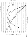
- FIG. 4 shows the progression of the axial unit depth over the relative unit radius of a fan wheel according to an embodiment of the present invention.
- the horizontal axis corresponds to the y-axis described above, and the vertical axis corresponds to the z-axis described above.
- the relative unit radius t(r) is plotted on the horizontal axis.
- the axial unit depth z*(t) of the blade is plotted on the vertical axis.
- the axial unit depth z*(t) is given by
- z * ⁇ ( t ) z HK ⁇ ( t ) - z VK ⁇ ( t ) R a - R i
- z VK (t) is the z-coordinate of the orthogonal projection of the leading edge VK in the sectional plane S passing through t
- z HK (t) is the z-coordinate of the orthogonal projection of the trailing edge HK in the sectional plane S passing through t.
- the progression of the axial unit depth z*(t) shown in this way has an aperiodically wave-like shape. It will be apparent that the axial unit depth z*(t), analogously to the orthogonal projection of the trailing edge HK, has a global minimum in the range from 65% to 90%, in particular from 70% to 85%, in particular 75% to 80%, of the relative unit radius t(r) of the blade.
- the orthogonal projection of the trailing edge HK and likewise the axial unit depth has no or at most one high point in the y-direction after the global minimum.
- the exemplary embodiment of the axial unit depth z*(t), and likewise the orthogonal projection of the trailing edge HK has an at least substantially continuously falling progression in the range from 0% to 50%, in particular from 0% to 40%, in particular 0% to 30%, of the relative unit radius t(r) of the blade 30 .
- a slight waviness is explicitly provided for here, in particular up to a maximum amplitude height of 0.05.
- the progression of the axial unit depth z*(t) of the exemplary embodiment of FIG. 4 as a function of the relative unit radius t(r), meets the following condition:
- the axial unit depth shown in FIG. 4 results at least substantially, in particular absolutely, from the following parameters:
- FIG. 5 shows a comparison of a fan wheel 1 previously known in the art with a fan wheel 1 according to an embodiment of the present invention.
- ⁇ 2 ⁇ ⁇ ⁇ ⁇ p t ⁇ 2 ⁇ ⁇ ⁇ ⁇ D 2 ⁇ n 2 a coefficient of performance ⁇ , which is a characteristic for an input power
- the shaft power of the electric motor is used; corresponding losses (heat, friction, etc.) of the electric motor are taken into account and represented in the overall efficiency ⁇ .
- FIG. 6 shows a radiator fan module 100 with the fan wheel 1 according to the present invention, according to the second aspect of the present invention.
- the radiator fan module 100 has a fan cowl 2 ; a fan wheel recess 40 is formed in the fan cowl 2 , and is bounded by a cowl ring 42 .
- a motor holder (hidden by the hub cup 10 ) is arranged within the fan wheel recess 40 and is mechanically connected with the fan cowl 2 via struts 44 .
- a motor (likewise hidden by the hub cup 10 ), in particular an electric motor, is at least partially held in the motor holder.
- a fan wheel 1 is arranged in the fan wheel recess 40 and is driven rotationally by the motor.
- the fan wheel 1 corresponds to an embodiment of a fan wheel according to the present invention. The detailed configuration of the fan wheel has been described above. According to the embodiment of FIG. 6 , the struts 44 are arranged behind the fan wheel in the flow direction, with the flow direction running perpendicularly into the illustration of FIG. 6 .
Landscapes
- Engineering & Computer Science (AREA)
- Mechanical Engineering (AREA)
- General Engineering & Computer Science (AREA)
- Chemical & Material Sciences (AREA)
- Combustion & Propulsion (AREA)
- Structures Of Non-Positive Displacement Pumps (AREA)
Abstract
Description
wherein Ri is an outer radius of the hub cup, which corresponds in particular at least substantially to an inner radius of the blade; Ra is an outer radius of the blade; and r is the distance between the axis of rotation and the particularly cylindrical sectional plane under consideration, which is perpendicular at distance r from the axis of rotation on the associated reference line, wherein r∈[Ri;Ra].
where:
wherein
Ri is an outer radius of the
Ra is an outer radius of the
r is the distance between the axis of rotation R and the sectional plane S under consideration, which is perpendicular at the distance r perpendicular from the axis of rotation R along the associated reference line G_REF, where r∈[Ri;Ra].
wherein
zVK(t) is the z-coordinate of the orthogonal projection of the leading edge VK in the sectional plane S passing through t; and
zHK(t) is the z-coordinate of the orthogonal projection of the trailing edge HK in the sectional plane S passing through t.
where:
a coefficient of performance λ, which is a characteristic for an input power;
and an efficiency η over a volume coefficient φ that quantifies a volumetric flow.
- 1 Fan wheel
- 2 Cowl
- 10 Hub cup
- 12 (Cylindrical) outer wall of the
hub cup 10 - 20 Outer ring
- 30 Blade
- 40 Fan wheel recess
- 42 Cowl ring
- 44 Struts
- 100 Radiator fan module
- HK Trailing edge
- VK Leading edge
- B Line of vision
- D Direction of rotation
- E Radial extent
- E_REF Reference plane
- G_REF Reference line
- GO Upper limit function for z*(t)
- GU Lower limit function for z*(t)
- HSR Main flow direction
- P1 First point
- P2 Second point
- r Distance between axis of rotation R and section plane S
- R Axis of rotation
- Ra Outer radius of the
blade 30 - Ri Outer radius of the
hub cup 10 - S Section plane
- y y-axis
- z z-axis
- z*(t) Axial unit depth
Claims (19)
Applications Claiming Priority (3)
| Application Number | Priority Date | Filing Date | Title |
|---|---|---|---|
| DE102017008292.8A DE102017008292A1 (en) | 2017-09-05 | 2017-09-05 | fan |
| DE102017008292 | 2017-09-05 | ||
| DE102017008292.8 | 2017-09-05 |
Publications (2)
| Publication Number | Publication Date |
|---|---|
| US20190072104A1 US20190072104A1 (en) | 2019-03-07 |
| US10697467B2 true US10697467B2 (en) | 2020-06-30 |
Family
ID=63371603
Family Applications (1)
| Application Number | Title | Priority Date | Filing Date |
|---|---|---|---|
| US16/122,153 Active 2038-12-21 US10697467B2 (en) | 2017-09-05 | 2018-09-05 | Fan wheel, radiator fan module and motor vehicle having the radiator fan module |
Country Status (8)
| Country | Link |
|---|---|
| US (1) | US10697467B2 (en) |
| EP (1) | EP3450717B1 (en) |
| KR (1) | KR102151458B1 (en) |
| CN (1) | CN109424582B (en) |
| DE (1) | DE102017008292A1 (en) |
| ES (1) | ES2902920T3 (en) |
| MX (1) | MX386694B (en) |
| RS (1) | RS62787B1 (en) |
Cited By (3)
| Publication number | Priority date | Publication date | Assignee | Title |
|---|---|---|---|---|
| US11085415B1 (en) * | 2017-12-22 | 2021-08-10 | Star Sailor Energy, Inc. | Wind generator system having a biomimetic aerodynamic element for use in improving the efficiency of the system |
| US11519422B2 (en) * | 2018-05-09 | 2022-12-06 | York Guangzhou Air Conditioning And Refrigeration Co., Ltd. | Blade and axial flow impeller using same |
| US20230175521A1 (en) * | 2021-12-03 | 2023-06-08 | Hamilton Sundstrand Corporation | Fan impeller with thin blades |
Families Citing this family (10)
| Publication number | Priority date | Publication date | Assignee | Title |
|---|---|---|---|---|
| USD289525S (en) * | 1984-10-01 | 1987-04-28 | Industrial Tools, Inc. | Slicing machine for magnetic tape or the like |
| USD901669S1 (en) | 2017-09-29 | 2020-11-10 | Carrier Corporation | Contoured fan blade |
| CN207795681U (en) * | 2018-01-13 | 2018-08-31 | 广东美的环境电器制造有限公司 | Axial flow fan blade, axial flow fan blade assembly, axial flow fan duct assembly |
| DE202019100367U1 (en) * | 2019-01-23 | 2020-04-24 | Brose Fahrzeugteile SE & Co. Kommanditgesellschaft, Würzburg | Fan wheel of a motor vehicle |
| CN110513329B (en) * | 2019-09-30 | 2024-07-19 | 广东美的制冷设备有限公司 | Axial flow fan and air conditioner having the same |
| DE102020210648A1 (en) * | 2020-08-21 | 2022-02-24 | Brose Fahrzeugteile SE & Co. Kommanditgesellschaft, Würzburg | Process for producing an injection molded part |
| DE102021201750A1 (en) * | 2021-02-24 | 2022-08-25 | Brose Fahrzeugteile SE & Co. Kommanditgesellschaft, Würzburg | Radiator fan module for a motor vehicle |
| US11808282B1 (en) | 2022-03-02 | 2023-11-07 | Aaon, Inc. | Propeller fan assembly with silencer seeds and concentric hub and method of use |
| US20240023271A1 (en) * | 2022-07-15 | 2024-01-18 | Dell Products L.P. | Noise attenuation fan |
| DE102024127886A1 (en) * | 2024-09-26 | 2026-03-26 | Mahle International Gmbh | fan wheel |
Citations (9)
| Publication number | Priority date | Publication date | Assignee | Title |
|---|---|---|---|---|
| US632740A (en) | 1898-09-09 | 1899-09-12 | Emerson Electric Mfg Co | Ventilating-fan. |
| US2684723A (en) | 1950-09-07 | 1954-07-27 | Guy S Faber | Propeller-type fan blade |
| US3416725A (en) | 1967-10-12 | 1968-12-17 | Acme Engineering And Mfg Corp | Dihedral bladed ventilating fan |
| US4684324A (en) * | 1985-08-02 | 1987-08-04 | Gate S.P.A. | Axial fan, particularly for motor vehicles |
| US6241474B1 (en) * | 1998-12-30 | 2001-06-05 | Valeo Thermique Moteur | Axial flow fan |
| EP1801422A2 (en) | 2005-12-22 | 2007-06-27 | Ziehl-Abegg AG | Fan and fan blade |
| US7422420B2 (en) * | 2004-07-06 | 2008-09-09 | Spal Automotive S.R.L. | Axial fan |
| US8137070B2 (en) * | 2010-03-10 | 2012-03-20 | Robert Bosch Gmbh | Skewed axial fan assembly |
| WO2012041565A1 (en) | 2010-09-29 | 2012-04-05 | Valeo Systemes Thermiques | Propeller for ventilator, with a variable chord length |
Family Cites Families (4)
| Publication number | Priority date | Publication date | Assignee | Title |
|---|---|---|---|---|
| DE2405050A1 (en) * | 1974-02-02 | 1975-08-07 | Motoren Turbinen Union | ROTATING BLADES FOR TURBO MACHINES |
| SE511657C2 (en) * | 1997-02-21 | 1999-11-01 | Scania Cv Ab | Fan ring seal |
| JP3978083B2 (en) * | 2001-06-12 | 2007-09-19 | 漢拏空調株式会社 | Axial fan |
| JP6490421B2 (en) * | 2014-12-25 | 2019-03-27 | テラル株式会社 | Rotor |
-
2017
- 2017-09-05 DE DE102017008292.8A patent/DE102017008292A1/en active Pending
-
2018
- 2018-08-23 EP EP18190530.8A patent/EP3450717B1/en active Active
- 2018-08-23 RS RS20211592A patent/RS62787B1/en unknown
- 2018-08-23 ES ES18190530T patent/ES2902920T3/en active Active
- 2018-09-04 CN CN201811025953.8A patent/CN109424582B/en active Active
- 2018-09-04 KR KR1020180105244A patent/KR102151458B1/en active Active
- 2018-09-04 MX MX2018010661A patent/MX386694B/en unknown
- 2018-09-05 US US16/122,153 patent/US10697467B2/en active Active
Patent Citations (11)
| Publication number | Priority date | Publication date | Assignee | Title |
|---|---|---|---|---|
| US632740A (en) | 1898-09-09 | 1899-09-12 | Emerson Electric Mfg Co | Ventilating-fan. |
| US2684723A (en) | 1950-09-07 | 1954-07-27 | Guy S Faber | Propeller-type fan blade |
| US3416725A (en) | 1967-10-12 | 1968-12-17 | Acme Engineering And Mfg Corp | Dihedral bladed ventilating fan |
| US4684324A (en) * | 1985-08-02 | 1987-08-04 | Gate S.P.A. | Axial fan, particularly for motor vehicles |
| US6241474B1 (en) * | 1998-12-30 | 2001-06-05 | Valeo Thermique Moteur | Axial flow fan |
| US7422420B2 (en) * | 2004-07-06 | 2008-09-09 | Spal Automotive S.R.L. | Axial fan |
| EP1801422A2 (en) | 2005-12-22 | 2007-06-27 | Ziehl-Abegg AG | Fan and fan blade |
| US20070201982A1 (en) | 2005-12-22 | 2007-08-30 | Ziehl-Abegg Ag | Ventilator and ventilator blade |
| US8137070B2 (en) * | 2010-03-10 | 2012-03-20 | Robert Bosch Gmbh | Skewed axial fan assembly |
| WO2012041565A1 (en) | 2010-09-29 | 2012-04-05 | Valeo Systemes Thermiques | Propeller for ventilator, with a variable chord length |
| US9970453B2 (en) | 2010-09-29 | 2018-05-15 | Valeo Systemes Thermiques | Propeller for ventilator, with a variable chord length |
Cited By (4)
| Publication number | Priority date | Publication date | Assignee | Title |
|---|---|---|---|---|
| US11085415B1 (en) * | 2017-12-22 | 2021-08-10 | Star Sailor Energy, Inc. | Wind generator system having a biomimetic aerodynamic element for use in improving the efficiency of the system |
| US11519422B2 (en) * | 2018-05-09 | 2022-12-06 | York Guangzhou Air Conditioning And Refrigeration Co., Ltd. | Blade and axial flow impeller using same |
| US20230175521A1 (en) * | 2021-12-03 | 2023-06-08 | Hamilton Sundstrand Corporation | Fan impeller with thin blades |
| US11754088B2 (en) * | 2021-12-03 | 2023-09-12 | Hamilton Sundstrand Corporation | Fan impeller with thin blades |
Also Published As
| Publication number | Publication date |
|---|---|
| CN109424582B (en) | 2021-05-28 |
| EP3450717B1 (en) | 2021-10-06 |
| DE102017008292A1 (en) | 2019-03-07 |
| US20190072104A1 (en) | 2019-03-07 |
| EP3450717A1 (en) | 2019-03-06 |
| KR20190026623A (en) | 2019-03-13 |
| ES2902920T3 (en) | 2022-03-30 |
| CN109424582A (en) | 2019-03-05 |
| MX2018010661A (en) | 2019-03-07 |
| MX386694B (en) | 2025-03-19 |
| KR102151458B1 (en) | 2020-09-03 |
| RS62787B1 (en) | 2022-02-28 |
Similar Documents
| Publication | Publication Date | Title |
|---|---|---|
| US10697467B2 (en) | Fan wheel, radiator fan module and motor vehicle having the radiator fan module | |
| US11022139B2 (en) | Fan wheel and radiator fan module with the fan wheel | |
| KR102296564B1 (en) | Cooling fan module | |
| US5577888A (en) | High efficiency, low-noise, axial fan assembly | |
| KR100978594B1 (en) | Automobile fan assembly with flared shroud and fan matching blade tip | |
| US12467474B2 (en) | Cooling fan and cooling fan module | |
| MXPA98000703A (en) | High efficiency axial fan assembly and under ru | |
| KR20180037072A (en) | Supercharger and method for cooling electric motor | |
| JP6639264B2 (en) | Nut for fixing compressor impeller, impeller assembly and supercharger | |
| JP6366851B2 (en) | AC generator for vehicles | |
| JPH0779543A (en) | Electric rotating machine | |
| JP2012087674A (en) | Inverter integrated electric compressor | |
| JP4375456B2 (en) | AC generator for brushless vehicles | |
| JP2005036664A (en) | Compressor, turbo-charger, and fuel cell | |
| US20210222561A1 (en) | Rotor having improved structure, and turbine and gas turbine including the same | |
| KR102432416B1 (en) | Turbocharger | |
| US11220953B2 (en) | Cooling fan module | |
| JP5057418B2 (en) | Axial fan | |
| US20130236325A1 (en) | Blade tip profile | |
| CN115030897B (en) | Compressor mounted to crankshaft | |
| JP2018021508A (en) | Fan device | |
| KR20080029434A (en) | Automotive Cooling Fans for Noise Reduction |
Legal Events
| Date | Code | Title | Description |
|---|---|---|---|
| FEPP | Fee payment procedure |
Free format text: ENTITY STATUS SET TO UNDISCOUNTED (ORIGINAL EVENT CODE: BIG.); ENTITY STATUS OF PATENT OWNER: LARGE ENTITY |
|
| AS | Assignment |
Owner name: BROSE FAHRZEUGTEILE GMBH & CO. KOMMANDITGESELLSCHA Free format text: ASSIGNMENT OF ASSIGNORS INTEREST;ASSIGNORS:FROH, CHRISTIAN;MAUSS, MICHAEL;REEL/FRAME:046812/0009 Effective date: 20180905 Owner name: BROSE FAHRZEUGTEILE GMBH & CO. KOMMANDITGESELLSCHAFT, WUERZBURG, GERMANY Free format text: ASSIGNMENT OF ASSIGNORS INTEREST;ASSIGNORS:FROH, CHRISTIAN;MAUSS, MICHAEL;REEL/FRAME:046812/0009 Effective date: 20180905 |
|
| STPP | Information on status: patent application and granting procedure in general |
Free format text: DOCKETED NEW CASE - READY FOR EXAMINATION |
|
| STPP | Information on status: patent application and granting procedure in general |
Free format text: NOTICE OF ALLOWANCE MAILED -- APPLICATION RECEIVED IN OFFICE OF PUBLICATIONS |
|
| STCF | Information on status: patent grant |
Free format text: PATENTED CASE |
|
| MAFP | Maintenance fee payment |
Free format text: PAYMENT OF MAINTENANCE FEE, 4TH YEAR, LARGE ENTITY (ORIGINAL EVENT CODE: M1551); ENTITY STATUS OF PATENT OWNER: LARGE ENTITY Year of fee payment: 4 |