US10697434B2 - Method for lifting a component of a multirotor wind turbine - Google Patents
Method for lifting a component of a multirotor wind turbine Download PDFInfo
- Publication number
- US10697434B2 US10697434B2 US16/090,683 US201716090683A US10697434B2 US 10697434 B2 US10697434 B2 US 10697434B2 US 201716090683 A US201716090683 A US 201716090683A US 10697434 B2 US10697434 B2 US 10697434B2
- Authority
- US
- United States
- Prior art keywords
- component
- tower structure
- hoisting mechanism
- load carrying
- wind turbine
- Prior art date
- Legal status (The legal status is an assumption and is not a legal conclusion. Google has not performed a legal analysis and makes no representation as to the accuracy of the status listed.)
- Expired - Fee Related, expires
Links
- 238000000034 method Methods 0.000 title claims abstract description 32
- 230000007246 mechanism Effects 0.000 claims abstract description 83
- 230000003247 decreasing effect Effects 0.000 claims description 6
- 240000007182 Ochroma pyramidale Species 0.000 description 1
- 230000005484 gravity Effects 0.000 description 1
- 238000012423 maintenance Methods 0.000 description 1
- 230000000087 stabilizing effect Effects 0.000 description 1
Images


Classifications
-
- F—MECHANICAL ENGINEERING; LIGHTING; HEATING; WEAPONS; BLASTING
- F03—MACHINES OR ENGINES FOR LIQUIDS; WIND, SPRING, OR WEIGHT MOTORS; PRODUCING MECHANICAL POWER OR A REACTIVE PROPULSIVE THRUST, NOT OTHERWISE PROVIDED FOR
- F03D—WIND MOTORS
- F03D13/00—Assembly, mounting or commissioning of wind motors; Arrangements specially adapted for transporting wind motor components
- F03D13/10—Assembly of wind motors; Arrangements for erecting wind motors
-
- F—MECHANICAL ENGINEERING; LIGHTING; HEATING; WEAPONS; BLASTING
- F03—MACHINES OR ENGINES FOR LIQUIDS; WIND, SPRING, OR WEIGHT MOTORS; PRODUCING MECHANICAL POWER OR A REACTIVE PROPULSIVE THRUST, NOT OTHERWISE PROVIDED FOR
- F03D—WIND MOTORS
- F03D1/00—Wind motors with rotation axis substantially parallel to the air flow entering the rotor
- F03D1/02—Wind motors with rotation axis substantially parallel to the air flow entering the rotor having a plurality of rotors
-
- F—MECHANICAL ENGINEERING; LIGHTING; HEATING; WEAPONS; BLASTING
- F05—INDEXING SCHEMES RELATING TO ENGINES OR PUMPS IN VARIOUS SUBCLASSES OF CLASSES F01-F04
- F05B—INDEXING SCHEME RELATING TO WIND, SPRING, WEIGHT, INERTIA OR LIKE MOTORS, TO MACHINES OR ENGINES FOR LIQUIDS COVERED BY SUBCLASSES F03B, F03D AND F03G
- F05B2230/00—Manufacture
- F05B2230/60—Assembly methods
- F05B2230/61—Assembly methods using auxiliary equipment for lifting or holding
-
- Y—GENERAL TAGGING OF NEW TECHNOLOGICAL DEVELOPMENTS; GENERAL TAGGING OF CROSS-SECTIONAL TECHNOLOGIES SPANNING OVER SEVERAL SECTIONS OF THE IPC; TECHNICAL SUBJECTS COVERED BY FORMER USPC CROSS-REFERENCE ART COLLECTIONS [XRACs] AND DIGESTS
- Y02—TECHNOLOGIES OR APPLICATIONS FOR MITIGATION OR ADAPTATION AGAINST CLIMATE CHANGE
- Y02E—REDUCTION OF GREENHOUSE GAS [GHG] EMISSIONS, RELATED TO ENERGY GENERATION, TRANSMISSION OR DISTRIBUTION
- Y02E10/00—Energy generation through renewable energy sources
- Y02E10/70—Wind energy
- Y02E10/72—Wind turbines with rotation axis in wind direction
-
- Y—GENERAL TAGGING OF NEW TECHNOLOGICAL DEVELOPMENTS; GENERAL TAGGING OF CROSS-SECTIONAL TECHNOLOGIES SPANNING OVER SEVERAL SECTIONS OF THE IPC; TECHNICAL SUBJECTS COVERED BY FORMER USPC CROSS-REFERENCE ART COLLECTIONS [XRACs] AND DIGESTS
- Y02—TECHNOLOGIES OR APPLICATIONS FOR MITIGATION OR ADAPTATION AGAINST CLIMATE CHANGE
- Y02P—CLIMATE CHANGE MITIGATION TECHNOLOGIES IN THE PRODUCTION OR PROCESSING OF GOODS
- Y02P70/00—Climate change mitigation technologies in the production process for final industrial or consumer products
- Y02P70/50—Manufacturing or production processes characterised by the final manufactured product
-
- Y02P70/523—
Definitions
- the present invention relates to a method for lifting a component of a multirotor wind turbine from an initial position, which is, according to the invention, at or near a base of a tower structure.
- the method allows lifting of the component to an operating position on a load carrying structure of the multirotor wind turbine.
- Wind turbines normally comprise one or more energy generating units, each energy generating unit comprising a rotor comprising a hub carrying one or more wind turbine blades.
- the wind acts on the wind turbine blades, thereby causing the hub to rotate.
- the rotational movements of the hub are transferred to a generator, either via a gear arrangement or directly, in the case that the wind turbine is of a so-called direct drive type.
- electrical energy is generated, which may be supplied to a power grid.
- Some wind turbines are provided with two or more energy generating units in order to increase the total power produced by the wind turbine, without having to provide the wind turbine with one very large, and therefore heavy, energy generating unit. Such wind turbines are sometimes referred to as ‘multirotor wind turbines’.
- the energy generating units may be carried by one or more load carrying structures which are, in turn, connected to a tower structure. Thereby at least some of the energy generating units are not mounted directly on the tower structure, and they may be positioned at a large distance away from the tower structure.
- GB 2 443 886 A discloses a multirotor wind turbine comprising a tower and at least two arms projecting outwards there from. A rotor is attached to an end of each arm. The rotors can be hoisted to or lowered from the arms along a substantially vertical direction.
- the invention provides a method for lifting a component of a multirotor wind turbine from an initial position to an operating position, the multirotor wind turbine comprising a tower structure and at least one load carrying structure being arranged for carrying at least one energy generating unit and for being connected to the tower structure, each load carrying structure extending away from the tower structure, the method comprising the steps of:
- the present invention relates to a method for lifting a component of a multirotor wind turbine.
- lifting should be interpreted as raising the component to a higher position compared to an initial level.
- the initial level may be the ground level, sea level, a level defined by a platform suitable for multirotor wind turbine, or any other suitable level where the component may be positioned prior to performing the method.
- the component could be any kind of element which is to be lifted and to form a part of the multirotor wind turbine. This will be described in further detail below.
- multirotor wind turbine should be interpreted to mean a wind turbine which comprises two or more energy generating units, each energy generating unit comprising a rotor.
- the initial position is to be interpreted as a starting position of the component.
- the component is to be placed at its initial position at the beginning of a lifting procedure.
- the initial position is at or near a base of the tower structure. From this initial position the component is to be moved to another position which is at a higher vertical level than the initial position.
- the operating position is to be interpreted as a position of the component where the component is arranged during the operation of the wind turbine. Once the component is in the operating position it may become an integral part of the multirotor wind turbine. It may be a final position of the component. The operating position is arranged at a higher level than the initial position.
- tower structure should be interpreted to mean a substantially vertical structure, arranged to carry the energy generating units of the multirotor wind turbine, at least partly via one or more load carrying structures.
- the tower structure is preferably anchored, at a lower part, to a foundation structure, defining a base of the tower structure. It is not ruled out that one or more energy generating units are mounted directly on the tower structure.
- the load carrying structure is arranged for carrying at least one energy generating unit, and for being connected to the tower structure of the multirotor wind turbine. Accordingly, the load carrying structure forms a connection between the energy generating unit and the tower structure, and is capable of handling the loads involved with carrying the energy generating units.
- the load carrying structure is connected to the tower structure at one end, and extends away from the tower structure, all the way to its free end.
- each energy generating unit thereby typically comprises a rotor, carrying a set of wind turbine blades, and a generator.
- the energy generating unit may further comprise a gear arrangement interconnecting the rotor and the generator.
- the generator, and possibly the gear arrangement, may be arranged inside a nacelle.
- a component is initially positioned at an initial position near a base of the tower structure. Accordingly, the component is initially positioned in a region close to the tower structure. This position is much closer to the base of the tower structure than to a point which is a vertical projection of the free end of the load carrying structure to a plane of the tower structure base. Accordingly, only a relatively small area around the base of the tower structure needs to be suitable for positioning a component to be lifted to the multirotor wind turbine.
- the energy generating unit could, e.g., be arranged on an access platform mounted on the tower structure near the sea level.
- the multirotor wind turbine is an onshore wind turbine
- only a small area around the wind turbine needs to be prepared for receiving a component.
- the ground in order to be suitable for having a component positioned thereon, the ground must be stabilized and possible trees must be cut down.
- the landscape must be suitable for the purpose, e.g. not containing steep slopes, etc. It is an advantage that only a small area around the tower structure of the multirotor wind turbine needs to fulfil these requirements.
- a first hoisting mechanism is provided at or near a connecting point between the tower structure and a load carrying structure. Furthermore, a second hoisting mechanism is provided at or near the operating position for the component. Accordingly, the second hoisting mechanism is arranged on the load carrying structure at or near the position where the component is to be mounted.
- a hoisting mechanism is to be understood as a mechanism for lifting and/or lowering a component. Accordingly, the component can be lifted to the operating position by means of the hoisting mechanisms, and without the need for an external crane. Furthermore, an external crane may only be required for erecting the tower structure. This reduces the costs of erecting the wind turbine.
- the operating position is arranged on the load carrying structure at a distance from the tower structure.
- the distance from the tower structure is to be interpreted as any position on the load carrying structure between the first end and the second end of the load carrying structure along a horizontal direction.
- the component When positioned at the distance from the tower structure the component creates a load with a centre of gravity which is displaced with respect to a tower structure.
- each of the first and second hoisting mechanism is operated in such a manner that the component is moved from the initial position to the operating position along a predetermined path.
- the predetermined path is further determined by the initial position, a position of the first and second hoisting mechanisms, and coordination between the first and second hoisting mechanisms.
- the predetermined path can be arbitrarily chosen, e.g. in order to match various requirements dictated by the site, the load handling capability of the tower structure and/or the load carrying structures, etc. For instance, it may be necessary to lift the component above one or more obstacles, such as trees, buildings, etc., in the vicinity of the multirotor wind turbine.
- the selected path can then be followed by appropriately operating the first and second hoisting mechanisms.
- the component may be lifted by the first hoisting mechanism by keeping it close to the tower structure in order to keep the balance of the entire multirotor wind turbine. Then only when the component is close to the top of the tower structure the second mechanism may pull the component in the horizontal direction and towards the operating position. Thereby the loads introduced into the load carrying structure and the tower structure during lifting of the component can be minimised.
- the component is mounted on the load carrying structure at the operating position.
- the component By mounting the component to the multirotor wind turbine, the component becomes an integral part of the wind turbine.
- the entire process of lifting a component described above may be reversed and therefore may serve as a process for lowering a component from an operating position to a position which is at a lower vertical level than the operating position.
- This may, e.g., be relevant in the case that a component needs to be replaced, during maintenance on a component or in the case that the wind turbine needs to be dismantled.
- the described method enables a lifting of a multirotor wind turbine component from a position which is near a base of a wind turbine tower structure.
- the multirotor wind turbine component is near the base only a small area around the multirotor wind turbine needs to be suitable for receiving the component.
- the hoisting mechanisms arranged at the multirotor wind turbine the component can be hoisted along any arbitrarily determined path. It is an advantage to have a possibility of choosing any path for hoisting a component of the multirotor wind turbine because, in that case, there is no need to clear a large area around the wind turbine in order to lift a component. There is no need to, for instance, cut down trees in the entire area of the multirotor wind turbine.
- the component can be kept close to the tower structure during hoisting and in that way keep the multirotor wind turbine balanced.
- the multirotor wind turbine is offshore, there is no need for any additional barge or the like since the component may be lifted from an already existing platform surrounding the tower structure.
- the component may be or form part of an energy generating unit.
- the component may be an entire energy generating unit, or it may be one or more parts of an energy generating unit, i.e. it may be a nacelle, a hub, a rotor, a rotor carrying one or more wind turbine blades, a wind turbine blade, a gear arrangement, a generator or a combination thereof.
- the operating position may be arranged at or near the free end of the load carrying structure.
- the component is mounted in a position which is as far away from the tower structure as possible.
- the operating position may be at another position along the load carrying structure, between the first end and the second, free end. It is not ruled out that a single load carrying structure may carry two or more energy generating units, mounted at various positions along the load carrying structure.
- the step of operating the first hoisting mechanism and the second hoisting mechanism may comprise decreasing a pull provided by the first hoisting mechanism and increasing a pull provided by the second hoisting mechanism during the hoisting of the component.
- the path along which the component is hoisted may be defined. For example, by initially operating only or mainly the first hoisting mechanism the pull provided thereof will lift the component along a substantially vertical direction, i.e. mainly parallel to the tower structure. After the component has been lifted to a certain height, the pull provided by the first hoisting mechanism may be gradually decreased while the pull provided by the second hoisting mechanism is gradually increasing.
- the component may be gradually lifted towards the top of the tower structure and simultaneously along a horizontal direction towards the second hoisting mechanism, i.e. towards the operating position thereof. In this manner the component may be lifted over various surrounding obstacles which can be avoided. Furthermore, when the component is close to the tower structure, the tower structure may shield the component from the wind during most of the hoisting.
- At least two components may be lifted substantially simultaneously to operating positions on load carrying structures arranged on opposite sides of the tower structure.
- at least two components are initially positioned near a base of the tower structure, each component being on the opposite sides of the tower structure.
- at least two first hoisting mechanisms may be provided at or near a connecting point between the tower structure and a respective load carrying structure, and at least two second hoisting mechanisms are also provided at the operating positions on the respective load carrying structures.
- all hoisting mechanisms may be operated simultaneously and synchronously. Thereby loads introduced in the tower structure and/or the load carrying structures during the hoisting of the components can be balanced, without requiring a separate counter balance.
- the at least two first hoisting mechanisms and the at least two second hoisting mechanisms may be operated in such a manner that the components are moved from the initial positions to the operating positions along predetermined paths.
- the components may also be simultaneously mounted at their operating positions, on the load carrying structures arranged on the opposite sides of the tower structures.
- the method may further comprise the step of mounting a wire between an operating position of at least one load carrying structure and a position on the tower structure at or near the base of the tower structure.
- the step of mounting a wire is preferably performed prior to the step of operating the first hoisting mechanism and the second hoisting mechanism.
- the wire may provide a counter balance, stabilizing the tower structure, in the case when only one component, typically being heavy, is to be lifted to the operating position.
- the wire may provide an additional safety mechanism. In this case, if one of the wires interconnecting a component and a hoisting mechanism breaks during the lifting process, an uneven load will abruptly be applied to the tower structure.
- the wire may serve as a guide for the component during at least part of the lifting process.
- at least part of the predetermined path is determined by the position of the wire.
- the tower structure may be provided with guy wires extending between a position on the tower structure and an anchor block arranged on the ground at a distance from the tower structure.
- Such guy wires may also provide the required counter balance as well as stability to the tower structure.
- the first hoisting mechanism and/or the second hoisting mechanism may comprise a winch.
- This winch may be operated in such a way that a pull provided by the winch of the first hoisting mechanism may decrease while a pull provided by the winch of the second hoisting mechanism is increasing during the hoisting of the component.
- At least one winch may be arranged at the position of the first or the second hoisting mechanism.
- at least one winch may be arranged in another position, e.g. on the ground, and be connected to a pulley arranged at the position of the first or second hoisting mechanism, e.g. via a wire or the like.
- first hoisting mechanism and/or the second hoisting mechanism may comprise a motor mechanism, a hydraulic mechanism, may be driven electrically, pneumatically or even manually.
- the hoisting mechanism may further comprise one or more chains, fibres, wires, ropes, or the like, serving as a lifting medium.
- a winch may form part of the first hoisting mechanism and the second hoisting mechanism may comprise a pulley, and the winch and pulley may be connected via a wire, rope or the like.
- the predetermined path may extend initially along a substantially vertical direction, from the initial position, and subsequently increasingly along a horizontal direction, towards the operating position.
- the component in order to obtain that the component is hoisted from the initial position near the base of the tower structure to the operating position, the component may initially be moved along a substantially vertical direction parallel to the tower structure by primarily operating the first hoisting mechanism. Subsequently, a pull provided by the first hoisting mechanism may be gradually decreased while a pull provided by the second hoisting mechanism is gradually increased. Thereby the component follows a path which is increasingly along a substantially horizontal direction perpendicular to the tower structure.
- FIGS. 1-4 illustrate a multirotor wind turbine during various steps of a method for lifting a component of a multirotor wind turbine from an initial position to an operating position according to a first embodiment of the invention
- FIGS. 5 and 6 illustrate a multirotor wind turbine during various steps of a method for lifting a component of a multirotor wind turbine from an initial position to an operating position according to a second embodiment of the invention.
- FIGS. 1-4 illustrate lifting of a component 1 a of a multirotor wind turbine 100 according to a first embodiment of the invention.
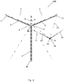
- FIG. 1 is a front view of a multirotor wind turbine 100 with a component 1 a to be lifted.
- the multirotor wind turbine 100 comprises a tower structure 2 and two load carrying structures 3 .
- a first end 4 of each load carrying structure 3 is mounted on the tower structure 2 , near the top 2b of the tower structure 2 .
- each load carrying structure may include an elongate beam.
- each of the load carrying structures 3 extends away from the tower structure 2 along an upwardly inclined direction, i.e.
- Each load carrying structure 3 comprises a secondary structure 6 , extending from the first end 4 of the load carrying structure 3 in an upwards direction.
- a wire 7 interconnects the secondary structure 6 of each load carrying structure 3 to the free end 5 of the load carrying structure 3 .
- the two secondary structures 6 are fixed to each other, e.g. by means of bolts, thereby fixing the load carrying structures 3 in the upwardly inclined direction.
- the component 1 a is arranged in an initial position near the base 2 a of the tower structure 2 .
- the component 1 a comprises a nacelle 9 , carrying a rotor 10 , and two wind turbine blades 11 being mounted on the rotor 10 .
- the wind turbine blades 11 are pointing in an upwards direction. This is sometimes referred to as a “bunny ear configuration”.
- the component may be only a nacelle 9 , and/or one wind turbine blade, and/or a rotor, or an entire energy generating unit.
- the component 1 a is connected to a first hoisting mechanism (not shown) arranged at or near the connection point, i.e. the first end 4 of one of the load carrying structures 3 , via a first wire 12 .
- the component 1 a is further connected to a second hoisting mechanism (not shown) arranged near the free end 5 of the load carrying structure 3 , via a second wire 13 .
- the component 1 a can be hoisted from the initial position illustrated in FIG. 1 to an operating position on the load carrying structure 3 by appropriately operating the first and second hoisting mechanisms.
- the operating position is at or near the free end 5 of the load carrying structure.
- the first and/or second hoisting mechanism may comprise a winch which is/are operated in such a way that a pull provided by the winch of the first hoisting mechanism is decreasing while a pull provided by the winch of the second hoisting mechanism is increasing during the hoisting of the component 1 a.
- FIG. 3 the hoisting of the component 1 a has been completed, and it has been mounted at the operating position at the free end 5 of the load carrying structure 3 . Furthermore, an additional component 1 b has been mounted on the other load carrying structure 3 , essentially as described above and illustrated in FIGS. 1 and 2 .
- FIG. 4 a third wind turbine blade 11 a , 11 b has further been mounted on the rotors 10 of each of the components 1 a and 1 b .
- the third wind turbine blades 11 a , 11 b may, e.g., have been lifted from the initial position near the base 2 a of the tower structure 2 to the rotors 10 , using the first and second hoisting mechanisms, and essentially in the manner described above and illustrated in FIGS. 1 and 2 .
- FIGS. 5 and 6 illustrate simultaneous lifting of two components 1 a , 1 b of a multirotor wind turbine 100 according to a second embodiment of the invention.
- the multirotor wind turbine 100 of FIGS. 5 and 6 is very similar to the multirotor wind turbine 100 of FIGS. 1-4 , and it will therefore not be described in further detail here.
- FIG. 5 illustrates the tower structure 2 with two load carrying structures 3 , together with two components 1 a and 1 b .
- the components 1 a and 1 b are arranged in their initial positions near the base 2 a of the tower structure 2 , and on opposite sides of the tower structure 2 .
- the components 1 a , 1 b are in the form of a nacelle 9 , without a rotor and wind turbine blades.
- the component 1 a is connected to a first hoisting mechanism (not shown) arranged at or near the connection point, i.e. the first end 4 of one of the load carrying structures 3 a , via a first wire 12 a .
- the component 1 a is further connected to a second hoisting mechanism (not shown) arranged near the free end 5 a of the load carrying structure 3 a , via a second wire 13 a .
- the component 1 b is connected to hoisting mechanisms at the load carrying structure 3 b , in the same manner as the component 1 a , via a first wire 12 b and a second wire 13 b . Accordingly, the situation illustrated in FIG. 5 is similar to the situation illustrated in FIG. 1 , except that two components 1 a , 1 b instead of one component are ready to be lifted.
- the components 1 a and 1 b are now simultaneously hoisted from the initial position by appropriately operating the first and second hoisting mechanisms.
- the hoisting mechanisms are being operated, and the components 1 a and 1 b are in the process of being lifted from the initial position illustrated in FIG. 5 towards the operating position on the load carrying structures 3 a and 3 b .
- the first and/or second hoisting mechanisms may comprise a winch which is operated in such a way that a pull provided by the winch of the first hoisting mechanism is decreasing while a pull provided by the winch of the second hoisting mechanism is increasing during the hoisting of the component 1 a .
- the hoisting mechanisms are operated simultaneously so that both components introduce similar loads on the wind turbine. In this manner the tower structure is balanced, having same loads on two opposite sides.
- the components 1 a , 1 b are subsequently mounted at the respective operating positions, similar to as it is illustrated by FIG. 3 .
- the operating positions are at or near the free ends 5 a and 5 b of the load carrying structures 3 a and 3 b , respectively.
- rotors, rotor blades and any other part of the energy generating unit may subsequently be lifted and mounted on the nacelles, similar to the situation illustrated in FIG. 4 .
Landscapes
- Engineering & Computer Science (AREA)
- Life Sciences & Earth Sciences (AREA)
- Sustainable Development (AREA)
- Sustainable Energy (AREA)
- Chemical & Material Sciences (AREA)
- Combustion & Propulsion (AREA)
- Mechanical Engineering (AREA)
- General Engineering & Computer Science (AREA)
- Wind Motors (AREA)
Abstract
Description
-
- positioning the component at an initial position near a base of the tower structure,
- providing a first hoisting mechanism at or near a connecting point between the tower structure and a load carrying structure,
- providing a second hoisting mechanism at or near an operating position for the component, said operating position being arranged on the load carrying structure at a distance from the tower structure,
- operating the first hoisting mechanism and the second hoisting mechanism in such a manner that the component is moved from the initial position to the operating position along a predetermined path, and
- mounting the component on the load carrying structure at the operating position.
Claims (8)
Applications Claiming Priority (4)
| Application Number | Priority Date | Filing Date | Title |
|---|---|---|---|
| DKPA201670279 | 2016-04-29 | ||
| DKPA201670279 | 2016-04-29 | ||
| DK201670279 | 2016-04-29 | ||
| PCT/DK2017/050124 WO2017186243A1 (en) | 2016-04-29 | 2017-04-27 | A method for lifting a component of a multirotor wind turbine |
Publications (2)
| Publication Number | Publication Date |
|---|---|
| US20190120210A1 US20190120210A1 (en) | 2019-04-25 |
| US10697434B2 true US10697434B2 (en) | 2020-06-30 |
Family
ID=60161224
Family Applications (1)
| Application Number | Title | Priority Date | Filing Date |
|---|---|---|---|
| US16/090,683 Expired - Fee Related US10697434B2 (en) | 2016-04-29 | 2017-04-27 | Method for lifting a component of a multirotor wind turbine |
Country Status (4)
| Country | Link |
|---|---|
| US (1) | US10697434B2 (en) |
| EP (1) | EP3449119B1 (en) |
| CN (1) | CN109072866B (en) |
| WO (1) | WO2017186243A1 (en) |
Families Citing this family (3)
| Publication number | Priority date | Publication date | Assignee | Title |
|---|---|---|---|---|
| WO2022122102A1 (en) * | 2020-12-11 | 2022-06-16 | Vestas Wind Systems A/S | Drop release for a nacelle in a wind turbine |
| CN117189493A (en) * | 2022-05-31 | 2023-12-08 | 金风科技股份有限公司 | Hoisting method of multi-impeller wind turbine generator |
| CN117189492A (en) * | 2022-05-31 | 2023-12-08 | 江苏金风科技有限公司 | Installation method of onshore double impeller wind turbine unit |
Citations (7)
| Publication number | Priority date | Publication date | Assignee | Title |
|---|---|---|---|---|
| CN1198509A (en) | 1998-05-04 | 1998-11-11 | 朱杰 | Wind motor |
| GB2443886A (en) | 2006-11-20 | 2008-05-21 | Michael Torr Todman | Multi rotor wind turbine |
| FR2919903A1 (en) | 2007-08-10 | 2009-02-13 | Vergnet Sa | Wind engine assembly displacing method for wind generator, involves avoiding carrying out connection/disconnection of driving system in event where system constitutes of driving axis directly connecting rotor of blades to electric generator |
| US20100005656A1 (en) | 2006-12-14 | 2010-01-14 | Bent Vangsy | A method for fitting the rotor of a wind generator |
| CN101737259A (en) | 2008-11-04 | 2010-06-16 | 上海宇风风电设备有限公司 | Wind power equipment |
| US20120228881A1 (en) | 2009-12-01 | 2012-09-13 | Aerodyn Engineering Gmbh | Wind Turbine Having a Lifting Device |
| US20160069321A1 (en) | 2014-09-09 | 2016-03-10 | General Electric Company | System and method for removing and/or installing a rotor blade of a wind turbine |
-
2017
- 2017-04-27 EP EP17720670.3A patent/EP3449119B1/en active Active
- 2017-04-27 CN CN201780024666.2A patent/CN109072866B/en active Active
- 2017-04-27 WO PCT/DK2017/050124 patent/WO2017186243A1/en not_active Ceased
- 2017-04-27 US US16/090,683 patent/US10697434B2/en not_active Expired - Fee Related
Patent Citations (7)
| Publication number | Priority date | Publication date | Assignee | Title |
|---|---|---|---|---|
| CN1198509A (en) | 1998-05-04 | 1998-11-11 | 朱杰 | Wind motor |
| GB2443886A (en) | 2006-11-20 | 2008-05-21 | Michael Torr Todman | Multi rotor wind turbine |
| US20100005656A1 (en) | 2006-12-14 | 2010-01-14 | Bent Vangsy | A method for fitting the rotor of a wind generator |
| FR2919903A1 (en) | 2007-08-10 | 2009-02-13 | Vergnet Sa | Wind engine assembly displacing method for wind generator, involves avoiding carrying out connection/disconnection of driving system in event where system constitutes of driving axis directly connecting rotor of blades to electric generator |
| CN101737259A (en) | 2008-11-04 | 2010-06-16 | 上海宇风风电设备有限公司 | Wind power equipment |
| US20120228881A1 (en) | 2009-12-01 | 2012-09-13 | Aerodyn Engineering Gmbh | Wind Turbine Having a Lifting Device |
| US20160069321A1 (en) | 2014-09-09 | 2016-03-10 | General Electric Company | System and method for removing and/or installing a rotor blade of a wind turbine |
Non-Patent Citations (2)
| Title |
|---|
| Danish Patent and Trademark Office, Examination Report in PA 201670279, dated Nov. 11, 2016. |
| European Patent Office, International Search Report and Written Opinion in PCT Application No. PCT/DK2017/050124, dated Jul. 31, 2017. |
Also Published As
| Publication number | Publication date |
|---|---|
| US20190120210A1 (en) | 2019-04-25 |
| WO2017186243A1 (en) | 2017-11-02 |
| EP3449119B1 (en) | 2022-02-09 |
| CN109072866B (en) | 2020-05-01 |
| CN109072866A (en) | 2018-12-21 |
| EP3449119A1 (en) | 2019-03-06 |
Similar Documents
| Publication | Publication Date | Title |
|---|---|---|
| EP3032097B1 (en) | Wind turbine tower with an elevator system | |
| KR102008156B1 (en) | Wind turbine tower erecting system | |
| EP3019433B1 (en) | Assembly and method for lifting loads | |
| EP2226502B1 (en) | Method and arrangement to install a wind-turbine | |
| US20180282134A1 (en) | Hoisting system for installing a wind turbine | |
| EP2280138A2 (en) | Lifting system and apparatus for constructing wind turbine towers | |
| US20120027523A1 (en) | Device and method for assembling a structure at sea | |
| EP2369174A1 (en) | A method of craneless mounting or demounting of a wind turbine blade | |
| US10156223B2 (en) | Hoisting systems and methods | |
| US10502189B2 (en) | Methods for erecting or dismantling a multirotor wind turbine | |
| CN104743455A (en) | Load Guiding Arrangement | |
| PL208973B1 (en) | Wind energy turbine | |
| JP2015506885A (en) | Weight lifting apparatus and method | |
| CA3216199A1 (en) | Crane assemblies and methods for erecting towers and wind turbines | |
| DK200800990A (en) | A method for erecting a wind turbine on an offshore site and a vessel for erecting a wind turbine on an offshore site | |
| CA3055870C (en) | Hoisting system for installing a wind turbine | |
| CN110691905B (en) | Multi-rotor wind turbine with guy cables | |
| US10697434B2 (en) | Method for lifting a component of a multirotor wind turbine | |
| EP2256079B1 (en) | Device for assembling a large structure at sea | |
| JP2020502425A (en) | Wind turbine with cable support structure | |
| TW202206699A (en) | Device and method for placing a component of a wind turbine | |
| WO2017186244A1 (en) | A method for erecting a multirotor wind turbine with elevated hub height | |
| US20220341397A1 (en) | Method of offshore mounting a wind turbine | |
| EP2532879A1 (en) | Assembly and/or maintenance of a wind turbine | |
| US20240003335A1 (en) | Mounting adapter for mounting rotor blades to a wind turbine and method for mounting rotor blades to a wind turbine |
Legal Events
| Date | Code | Title | Description |
|---|---|---|---|
| AS | Assignment |
Owner name: VESTAS WIND SYSTEMS A/S, DENMARK Free format text: ASSIGNMENT OF ASSIGNORS INTEREST;ASSIGNORS:BAUN, TORBEN LADEGAARD;PEDERSEN, GUNNAR K. STORGAARD;JENSEN, IVAR J.B.K.;SIGNING DATES FROM 20180926 TO 20180927;REEL/FRAME:047037/0611 |
|
| FEPP | Fee payment procedure |
Free format text: ENTITY STATUS SET TO UNDISCOUNTED (ORIGINAL EVENT CODE: BIG.); ENTITY STATUS OF PATENT OWNER: LARGE ENTITY |
|
| STPP | Information on status: patent application and granting procedure in general |
Free format text: DOCKETED NEW CASE - READY FOR EXAMINATION |
|
| STPP | Information on status: patent application and granting procedure in general |
Free format text: NON FINAL ACTION MAILED |
|
| STPP | Information on status: patent application and granting procedure in general |
Free format text: RESPONSE TO NON-FINAL OFFICE ACTION ENTERED AND FORWARDED TO EXAMINER |
|
| STPP | Information on status: patent application and granting procedure in general |
Free format text: NOTICE OF ALLOWANCE MAILED -- APPLICATION RECEIVED IN OFFICE OF PUBLICATIONS |
|
| STCF | Information on status: patent grant |
Free format text: PATENTED CASE |
|
| FEPP | Fee payment procedure |
Free format text: MAINTENANCE FEE REMINDER MAILED (ORIGINAL EVENT CODE: REM.); ENTITY STATUS OF PATENT OWNER: LARGE ENTITY |
|
| LAPS | Lapse for failure to pay maintenance fees |
Free format text: PATENT EXPIRED FOR FAILURE TO PAY MAINTENANCE FEES (ORIGINAL EVENT CODE: EXP.); ENTITY STATUS OF PATENT OWNER: LARGE ENTITY |
|
| STCH | Information on status: patent discontinuation |
Free format text: PATENT EXPIRED DUE TO NONPAYMENT OF MAINTENANCE FEES UNDER 37 CFR 1.362 |
|
| FP | Lapsed due to failure to pay maintenance fee |
Effective date: 20240630 |