US10697418B2 - Hybrid vehicle - Google Patents
Hybrid vehicle Download PDFInfo
- Publication number
- US10697418B2 US10697418B2 US16/244,437 US201916244437A US10697418B2 US 10697418 B2 US10697418 B2 US 10697418B2 US 201916244437 A US201916244437 A US 201916244437A US 10697418 B2 US10697418 B2 US 10697418B2
- Authority
- US
- United States
- Prior art keywords
- decompression
- cylinders
- internal combustion
- engine
- power train
- Prior art date
- Legal status (The legal status is an assumption and is not a legal conclusion. Google has not performed a legal analysis and makes no representation as to the accuracy of the status listed.)
- Expired - Fee Related, expires
Links
Images


Classifications
-
- B—PERFORMING OPERATIONS; TRANSPORTING
- B60—VEHICLES IN GENERAL
- B60W—CONJOINT CONTROL OF VEHICLE SUB-UNITS OF DIFFERENT TYPE OR DIFFERENT FUNCTION; CONTROL SYSTEMS SPECIALLY ADAPTED FOR HYBRID VEHICLES; ROAD VEHICLE DRIVE CONTROL SYSTEMS FOR PURPOSES NOT RELATED TO THE CONTROL OF A PARTICULAR SUB-UNIT
- B60W20/00—Control systems specially adapted for hybrid vehicles
-
- F—MECHANICAL ENGINEERING; LIGHTING; HEATING; WEAPONS; BLASTING
- F02—COMBUSTION ENGINES; HOT-GAS OR COMBUSTION-PRODUCT ENGINE PLANTS
- F02B—INTERNAL-COMBUSTION PISTON ENGINES; COMBUSTION ENGINES IN GENERAL
- F02B21/00—Engines characterised by air-storage chambers
- F02B21/02—Chamber shapes or constructions
-
- F—MECHANICAL ENGINEERING; LIGHTING; HEATING; WEAPONS; BLASTING
- F02—COMBUSTION ENGINES; HOT-GAS OR COMBUSTION-PRODUCT ENGINE PLANTS
- F02D—CONTROLLING COMBUSTION ENGINES
- F02D13/00—Controlling the engine output power by varying inlet or exhaust valve operating characteristics, e.g. timing
- F02D13/02—Controlling the engine output power by varying inlet or exhaust valve operating characteristics, e.g. timing during engine operation
- F02D13/0223—Variable control of the intake valves only
- F02D13/0234—Variable control of the intake valves only changing the valve timing only
-
- F—MECHANICAL ENGINEERING; LIGHTING; HEATING; WEAPONS; BLASTING
- F02—COMBUSTION ENGINES; HOT-GAS OR COMBUSTION-PRODUCT ENGINE PLANTS
- F02D—CONTROLLING COMBUSTION ENGINES
- F02D13/00—Controlling the engine output power by varying inlet or exhaust valve operating characteristics, e.g. timing
- F02D13/02—Controlling the engine output power by varying inlet or exhaust valve operating characteristics, e.g. timing during engine operation
- F02D13/0276—Actuation of an additional valve for a special application, e.g. for decompression, exhaust gas recirculation or cylinder scavenging
-
- F—MECHANICAL ENGINEERING; LIGHTING; HEATING; WEAPONS; BLASTING
- F02—COMBUSTION ENGINES; HOT-GAS OR COMBUSTION-PRODUCT ENGINE PLANTS
- F02D—CONTROLLING COMBUSTION ENGINES
- F02D13/00—Controlling the engine output power by varying inlet or exhaust valve operating characteristics, e.g. timing
- F02D13/02—Controlling the engine output power by varying inlet or exhaust valve operating characteristics, e.g. timing during engine operation
- F02D13/04—Controlling the engine output power by varying inlet or exhaust valve operating characteristics, e.g. timing during engine operation using engine as brake
-
- F—MECHANICAL ENGINEERING; LIGHTING; HEATING; WEAPONS; BLASTING
- F02—COMBUSTION ENGINES; HOT-GAS OR COMBUSTION-PRODUCT ENGINE PLANTS
- F02D—CONTROLLING COMBUSTION ENGINES
- F02D41/00—Electrical control of supply of combustible mixture or its constituents
- F02D41/02—Circuit arrangements for generating control signals
- F02D41/04—Introducing corrections for particular operating conditions
- F02D41/12—Introducing corrections for particular operating conditions for deceleration
- F02D41/123—Introducing corrections for particular operating conditions for deceleration the fuel injection being cut-off
-
- F—MECHANICAL ENGINEERING; LIGHTING; HEATING; WEAPONS; BLASTING
- F02—COMBUSTION ENGINES; HOT-GAS OR COMBUSTION-PRODUCT ENGINE PLANTS
- F02N—STARTING OF COMBUSTION ENGINES; STARTING AIDS FOR SUCH ENGINES, NOT OTHERWISE PROVIDED FOR
- F02N11/00—Starting of engines by means of electric motors
- F02N11/04—Starting of engines by means of electric motors the motors being associated with current generators
-
- F—MECHANICAL ENGINEERING; LIGHTING; HEATING; WEAPONS; BLASTING
- F02—COMBUSTION ENGINES; HOT-GAS OR COMBUSTION-PRODUCT ENGINE PLANTS
- F02N—STARTING OF COMBUSTION ENGINES; STARTING AIDS FOR SUCH ENGINES, NOT OTHERWISE PROVIDED FOR
- F02N19/00—Starting aids for combustion engines, not otherwise provided for
- F02N19/004—Aiding engine start by using decompression means or variable valve actuation
-
- F—MECHANICAL ENGINEERING; LIGHTING; HEATING; WEAPONS; BLASTING
- F02—COMBUSTION ENGINES; HOT-GAS OR COMBUSTION-PRODUCT ENGINE PLANTS
- F02N—STARTING OF COMBUSTION ENGINES; STARTING AIDS FOR SUCH ENGINES, NOT OTHERWISE PROVIDED FOR
- F02N9/00—Starting of engines by supplying auxiliary pressure fluid to their working chambers
- F02N9/04—Starting of engines by supplying auxiliary pressure fluid to their working chambers the pressure fluid being generated otherwise, e.g. by compressing air
-
- B—PERFORMING OPERATIONS; TRANSPORTING
- B60—VEHICLES IN GENERAL
- B60W—CONJOINT CONTROL OF VEHICLE SUB-UNITS OF DIFFERENT TYPE OR DIFFERENT FUNCTION; CONTROL SYSTEMS SPECIALLY ADAPTED FOR HYBRID VEHICLES; ROAD VEHICLE DRIVE CONTROL SYSTEMS FOR PURPOSES NOT RELATED TO THE CONTROL OF A PARTICULAR SUB-UNIT
- B60W2710/00—Output or target parameters relating to a particular sub-units
- B60W2710/06—Combustion engines, Gas turbines
-
- F—MECHANICAL ENGINEERING; LIGHTING; HEATING; WEAPONS; BLASTING
- F01—MACHINES OR ENGINES IN GENERAL; ENGINE PLANTS IN GENERAL; STEAM ENGINES
- F01L—CYCLICALLY OPERATING VALVES FOR MACHINES OR ENGINES
- F01L13/00—Modifications of valve-gear to facilitate reversing, braking, starting, changing compression ratio, or other specific operations
- F01L13/08—Modifications of valve-gear to facilitate reversing, braking, starting, changing compression ratio, or other specific operations for decompression, e.g. during starting; for changing compression ratio
-
- F—MECHANICAL ENGINEERING; LIGHTING; HEATING; WEAPONS; BLASTING
- F01—MACHINES OR ENGINES IN GENERAL; ENGINE PLANTS IN GENERAL; STEAM ENGINES
- F01L—CYCLICALLY OPERATING VALVES FOR MACHINES OR ENGINES
- F01L2800/00—Methods of operation using a variable valve timing mechanism
- F01L2800/01—Starting
-
- F—MECHANICAL ENGINEERING; LIGHTING; HEATING; WEAPONS; BLASTING
- F01—MACHINES OR ENGINES IN GENERAL; ENGINE PLANTS IN GENERAL; STEAM ENGINES
- F01L—CYCLICALLY OPERATING VALVES FOR MACHINES OR ENGINES
- F01L2800/00—Methods of operation using a variable valve timing mechanism
- F01L2800/03—Stopping; Stalling
-
- F—MECHANICAL ENGINEERING; LIGHTING; HEATING; WEAPONS; BLASTING
- F02—COMBUSTION ENGINES; HOT-GAS OR COMBUSTION-PRODUCT ENGINE PLANTS
- F02B—INTERNAL-COMBUSTION PISTON ENGINES; COMBUSTION ENGINES IN GENERAL
- F02B23/00—Other engines characterised by special shape or construction of combustion chambers to improve operation
- F02B23/08—Other engines characterised by special shape or construction of combustion chambers to improve operation with positive ignition
- F02B23/10—Other engines characterised by special shape or construction of combustion chambers to improve operation with positive ignition with separate admission of air and fuel into cylinder
- F02B23/101—Other engines characterised by special shape or construction of combustion chambers to improve operation with positive ignition with separate admission of air and fuel into cylinder the injector being placed on or close to the cylinder centre axis, e.g. with mixture formation using spray guided concepts
-
- F—MECHANICAL ENGINEERING; LIGHTING; HEATING; WEAPONS; BLASTING
- F02—COMBUSTION ENGINES; HOT-GAS OR COMBUSTION-PRODUCT ENGINE PLANTS
- F02D—CONTROLLING COMBUSTION ENGINES
- F02D2200/00—Input parameters for engine control
- F02D2200/50—Input parameters for engine control said parameters being related to the vehicle or its components
-
- F—MECHANICAL ENGINEERING; LIGHTING; HEATING; WEAPONS; BLASTING
- F02—COMBUSTION ENGINES; HOT-GAS OR COMBUSTION-PRODUCT ENGINE PLANTS
- F02D—CONTROLLING COMBUSTION ENGINES
- F02D29/00—Controlling engines, such controlling being peculiar to the devices driven thereby, the devices being other than parts or accessories essential to engine operation, e.g. controlling of engines by signals external thereto
- F02D29/02—Controlling engines, such controlling being peculiar to the devices driven thereby, the devices being other than parts or accessories essential to engine operation, e.g. controlling of engines by signals external thereto peculiar to engines driving vehicles; peculiar to engines driving variable pitch propellers
-
- F—MECHANICAL ENGINEERING; LIGHTING; HEATING; WEAPONS; BLASTING
- F02—COMBUSTION ENGINES; HOT-GAS OR COMBUSTION-PRODUCT ENGINE PLANTS
- F02D—CONTROLLING COMBUSTION ENGINES
- F02D35/00—Controlling engines, dependent on conditions exterior or interior to engines, not otherwise provided for
- F02D35/02—Controlling engines, dependent on conditions exterior or interior to engines, not otherwise provided for on interior conditions
- F02D35/023—Controlling engines, dependent on conditions exterior or interior to engines, not otherwise provided for on interior conditions by determining the cylinder pressure
-
- F—MECHANICAL ENGINEERING; LIGHTING; HEATING; WEAPONS; BLASTING
- F02—COMBUSTION ENGINES; HOT-GAS OR COMBUSTION-PRODUCT ENGINE PLANTS
- F02N—STARTING OF COMBUSTION ENGINES; STARTING AIDS FOR SUCH ENGINES, NOT OTHERWISE PROVIDED FOR
- F02N2200/00—Parameters used for control of starting apparatus
- F02N2200/02—Parameters used for control of starting apparatus said parameters being related to the engine
- F02N2200/021—Engine crank angle
-
- F—MECHANICAL ENGINEERING; LIGHTING; HEATING; WEAPONS; BLASTING
- F02—COMBUSTION ENGINES; HOT-GAS OR COMBUSTION-PRODUCT ENGINE PLANTS
- F02N—STARTING OF COMBUSTION ENGINES; STARTING AIDS FOR SUCH ENGINES, NOT OTHERWISE PROVIDED FOR
- F02N2200/00—Parameters used for control of starting apparatus
- F02N2200/02—Parameters used for control of starting apparatus said parameters being related to the engine
- F02N2200/022—Engine speed
-
- Y—GENERAL TAGGING OF NEW TECHNOLOGICAL DEVELOPMENTS; GENERAL TAGGING OF CROSS-SECTIONAL TECHNOLOGIES SPANNING OVER SEVERAL SECTIONS OF THE IPC; TECHNICAL SUBJECTS COVERED BY FORMER USPC CROSS-REFERENCE ART COLLECTIONS [XRACs] AND DIGESTS
- Y02—TECHNOLOGIES OR APPLICATIONS FOR MITIGATION OR ADAPTATION AGAINST CLIMATE CHANGE
- Y02T—CLIMATE CHANGE MITIGATION TECHNOLOGIES RELATED TO TRANSPORTATION
- Y02T10/00—Road transport of goods or passengers
- Y02T10/60—Other road transportation technologies with climate change mitigation effect
- Y02T10/62—Hybrid vehicles
Definitions
- the present disclosure relates to a hybrid vehicle and more particularly to a hybrid vehicle provided with, as well as a drive motor unit, an internal combustion engine having a decompression device for releasing compression pressure in a cylinder.
- An internal combustion engine provided with a decompression device (also called a pressure reducing device) for releasing compression pressure in a cylinder.
- This kind of decompression device is configured to be able to select between a state in which a decompression operation to release the compression pressure in the cylinder is performed (hereunder, referred to as a “decompression operating state”) and a state in which the decompression operation described above is not performed even if a crankshaft is rotating (hereunder, referred to as a “decompression stop state”).
- JP 2014-047695 A discloses a control device for an internal combustion engine that includes the decompression device as described above.
- this control device controls the decompression device such that the decompression operating state in the course of engine stop and in the course of engine start-up is selected.
- an example of this decompression device is a variable valve operating device that can change the closing timing of an intake valve. The decompression operating state is achieved by retarding the closing timing of the intake valve.
- a hybrid vehicle provided with a power train that includes an internal combustion engine having a plurality of cylinders and a drive motor unit having an electric motor coupled to the internal combustion engine without a clutch therebetween.
- this kind of hybrid vehicle it is effective to install a decompression device in order to reduce vibration and noise associated with resonance of the power train due to compression of the internal combustion engine (i.e. excitation force) in the course of engine stop and the course of engine start-up in which combustion is not performed.
- a decompression device in order to reduce vibration and noise associated with resonance of the power train due to compression of the internal combustion engine (i.e. excitation force) in the course of engine stop and the course of engine start-up in which combustion is not performed.
- the resonance occurs at the power train in an engine speed range (hereunder, referred to as a “first power train resonance range”) that centers on an engine speed value at which the period of excitation due to the compression coincides with a natural vibration period of the drive motor unit. If the decompression device is provided for each of all the cylinders, the resonance can be reduced by the use of the decompression device in this kind of first power train resonance range.
- the decompression device for only a subset of one or more cylinders (that is, one or more but not all the cylinders of the internal combustion engine) for reducing cost.
- the resonance may not be properly reduced in the first power train resonance range described above.
- the present disclosure has been made to address the problem described above, and an object of the present disclosure is to provide a hybrid vehicle that can reduce resonance in a first power train resonance range by the use of a decompression device while reducing cost by decreasing the number of cylinders having the decompression device.
- a hybrid vehicle includes a power train including an internal combustion engine equipped with a plurality of cylinders and a drive motor unit.
- the drive motor unit includes an electric motor coupled to the internal combustion engine without a clutch interposed between the drive motor unit and the internal combustion engine.
- the internal combustion engine includes one or more decompression devices that are each installed for a subset of one or more cylinders that are one or more but not all of the plurality of cylinders, the one or more decompression devices operating to release compression pressure in the subset of one or more cylinders in at least one of a course of an engine stop and course of an engine start-up in which combustion is not performed.
- the subset of one or more cylinders are selected such that, when the one or more decompression devices are operating, compression is not produced sequentially in cylinders that are adjacent to each other in terms of a firing order of the internal combustion engine.
- the hybrid vehicle may further include a control device.
- the control device In stopping an operation of the one or more decompression devices in the course of the engine start-up, the control device may be configured, when an engine speed is higher than an upper limit value of a first power train resonance range and is lower than a lower limit value of a second power train resonance range located on a higher engine speed side relative to the first power train resonance range, to stop the operation of the one or more decompression devices.
- the first power train resonance range may be an engine speed range that centers on an engine speed value at which a period of excitation due to compression in the internal combustion engine coincides with a natural vibration period of the motor drive unit when the operation of the one or more decompression devices is stopped.
- the second power train resonance range may be an engine speed range that centers on an engine speed value at which the period of the excitation coincides with the natural vibration period of the drive motor unit when the one or more decompression device are operating.
- the hybrid vehicle may further include a control device.
- the control device In operating the one or more decompression devices in the course of the engine stop, the control device may be configured, when an engine speed is higher than an upper limit value of a first power train resonance range and is lower than a lower limit value of a second power train resonance range located on a higher engine speed side relative to the first power train resonance range, to operate the one or more decompression devices.
- the first power train resonance range may be an engine speed range that centers on an engine speed value at which a period of excitation due to compression in the internal combustion engine coincides with a natural vibration period of the motor drive unit when an operation of the one or more decompression devices is stopped.
- the second power train resonance range may be an engine speed range that centers on an engine speed value at which the period of the excitation coincides with the natural vibration period of the drive motor unit when the one or more decompression device are operating.
- the one or more decompression devices are installed for the subset of one or more cylinders that are selected such that, when the one or more decompression devices are operating, compression is not produced sequentially in cylinders that are adjacent to each other in terms of the firing order.
- the value of engine speed at which the period of the excitation due to the compression in the internal combustion engine coincides with the natural vibration period of the motor drive unit can be made higher as compared to when the compression is performed in all the cylinders of the internal combustion engine.
- resonance in the first power train resonance range can be reduced by the use of the one or more decompression devices similarly to the example in which a decompression device is installed for all the cylinders, while reducing cost by decreasing the number of cylinders having the decompression device.
- FIG. 1 is a schematic diagram for describing an example of the configuration of a power train of a hybrid vehicle according to a first embodiment of the present disclosure
- FIG. 2 is a schematic diagram for describing an example of the concrete configuration of a decompression device shown in FIG. 1 ;
- FIG. 3 is a schematic diagram for describing an example of the concrete configuration of the decompression device shown in FIG. 1 ;
- FIGS. 4A and 4B are diagrams for describing advantageous Effects of installation of the decompression devices to a subset of one or more cylinders (i.e., #2 and #3);
- FIG. 5 is a diagram for describing an engine speed range in which resonance is produced in the power train due to compression of an internal combustion engine
- FIG. 6 is a diagram for describing an issue on installation of the decompression devices into the subset of one or more cylinders (#2 and #3) as in the first embodiment;
- FIG. 7 is a diagram for describing control of the decompression device according to a second embodiment of the present disclosure.
- FIG. 8 is a flow chart that illustrates a routine of the processing concerning control of the decompression device in the course of engine start-up according to the second embodiment of present disclosure
- FIG. 9 is a flow chart that illustrates a routine of the processing concerning control of the decompression device in the course of engine stop according to the second embodiment of present disclosure
- FIGS. 10A and 10B are diagrams for describing an example of selection of cylinders having the decompression device with respect to an in-line two-cylinder internal combustion engine
- FIGS. 11A and 11B are diagrams for describing an example of selection of cylinders having the decompression device with respect to an in-line three-cylinder internal combustion engine
- FIGS. 12A and 12B are diagrams for describing an example of selection of cylinders having the decompression device with respect to a V-type six-cylinder internal combustion engine.
- FIGS. 13A and 13B are diagrams for describing an example of selection of cylinders having the decompression device with respect to a V-type eight-cylinder internal combustion engine.
- FIGS. 1 to 5 a first embodiment according to the present disclosure will be described with reference to FIGS. 1 to 5 .
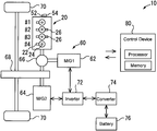
- FIG. 1 is a schematic diagram for describing an example of the configuration of a power train 10 of a hybrid vehicle according to the first embodiment of the present disclosure.
- the power train 10 shown in FIG. 1 is provided with an internal combustion engine 20 and a drive motor unit 60 as power sources of the hybrid vehicle.
- the internal combustion engine 20 is a spark ignition in-line four-cylinder engine and has first to fourth cylinders #1 to #4 in order from its one end in the cylinder row direction.
- an internal combustion engine according to the present disclosure may alternatively be a compression ignition engine, as long as it has a plurality of cylinders.
- the internal combustion engine 20 is equipped with fuel injection valves 22 and an ignition device 24 (only spark plugs are illustrated).
- Each of the fuel injection valves 22 is arranged in a cylinder, and, as an example, injects fuel directly into the cylinder.
- the ignition device 24 ignites an air-fuel mixture in each cylinder by the use of the spark plug arranged for each cylinder.
- FIGS. 2 and 3 are schematic diagrams for describing an example of the concrete configuration of the decompression device 26 shown in FIG. 1 . It should be noted that FIGS. 2 and 3 represent the configuration concerning the cylinders having the decompression device 26 .
- FIG. 2 illustrates an intake valve 28 , a rocker arm 32 that transmits pressing force from an intake cam 30 to the intake valve 28 , and a hydraulic lash adjustor (HLA) 34 that supports the rocker arm 32 at its end portion located on the non-valve side.
- the intake valve 28 is urged, by a valve spring 36 , in its closing direction (that is, a direction to push up the rocker arm 32 ).
- FIG. 3 illustrates two rocker arms 32 and two HLAs 34 that are respectively associated with two (one example) intake valves 28 in each cylinder for which the decompression device 26 is installed.
- the decompression device 26 is equipped with HLA holders 38 , a slider 40 , HLA lifters 42 and an actuator 44 .
- each of the HLA holders 38 is fixed to a cylinder head 46 , formed into a bottomed cylindrical shape and houses the corresponding HLA 34 such that it can be lifted and lowered.
- Each of the sliders 40 is driven by the corresponding actuator 44 to reciprocate in the cylinder row direction (i.e., the left-right direction in FIG. 3 ).
- Each of the sliders 40 has a cam surface 40 a for transforming the reciprocating motion of the slider 40 to the lifting and lowering motion of the corresponding HLA 34 (i.e., reciprocating motion in the top-bottom direction of FIG. 3 ).
- Each of the HLA lifters 42 is interposed between the bottom surface of the corresponding HLA 34 and the cam surface 40 a of the corresponding slider 40 .
- the actuators 44 are of electrically driven type, for example.
- Each of the HLAs 34 operates so as to always eliminate a clearance between the intake cam 30 and the rocker arm 32 with its original function (i.e., expansion and contraction motion).
- the position of the slider 40 is adjusted by the use of the actuator 44 , and, as a result, the intake valve 28 can be caused to remain open, by the use of the HLA 34 , regardless of application of the pressing force of the intake cam 30 to the rocker arm 32 . More specifically, when the cam surface 40 a is located as shown by the solid line in FIG. 3 , the intake valve 28 normally opens and closes.
- the HLA 34 lifts, by the effects of the cam surface 40 a , on the side of the rocker arm 32 via the HLA lifter 42 . If a state of the HLA 34 being lifted is achieved, the intake valve 28 can be caused to remain open regardless of application of the pressing force of the intake cam 30 to the rocker arm 32 .
- the in-cylinder pressure (i.e., compression pressure) in the compression stroke can be released in the cylinder the decompression device 26 .
- a decompression operation an operation to release the compression pressure in each cylinder in this manner is referred to as a “decompression operation”
- the decompression device 26 configured as described above, by operating the actuator 44 to lift the HLA 34 as described above, a “decompression operating state” in which the decompression operation is performed is achieved. On the other hand, by operating the actuator 44 such the lifting of the HLA 34 is eliminated, a “decompression stop state” in which the decompression operation is not performed is obtained (even if the crankshaft 52 is rotating). As just described, the decompression device 26 can select between the decompression operating state and the decompression stop state by controlling the actuator 44 . It should be noted that the concrete configuration of a decompression device according to the present disclosure is not limited to the example shown in FIGS. 2 and 3 . That is to say, if the compression pressure in the cylinder can be released, a decompression device having any other known configuration can be adopted.
- crank angle sensor 54 that outputs a signal responsive to the crank angle is arranged in the vicinity of the crankshaft 52 of the internal combustion engine 20 .
- the drive motor unit 60 is equipped with a first motor generator (M/G1) 62 and a second motor generator (M/G2) 64 , which each correspond to an electric motor that can generate electric power, and a power split device 66 .
- the motor generator 62 and the motor generator 64 are alternate current synchronous motor generators having both a function as an electric motor that outputs a torque using a supplied electric power and a function as a generator that transduces an inputted mechanical power into the electric power.
- the first motor generator 62 is mainly used as a generator
- the second motor generator 64 is mainly used as an electric motor.
- the first motor generator 62 is simply noted as the generator 62
- the second motor generator 64 is simply noted as the motor 64 .
- the internal combustion engine 20 , the generator 62 and the motor 64 are coupled to wheels 70 via the power split device 66 and a speed reducer 68 .
- the power split device 66 is, for example, a planetary gear unit and splits the torque outputted from the internal combustion engine 20 into torques of the generator 62 and the wheels 70 .
- a sun gear is coupled to a rotational shaft of the generator 62 ;
- a planetary carrier is coupled to the crankshaft 52 of the internal combustion engine 20 ;
- a ring gear is coupled to a rotational shaft of the motor 64 .
- the torque outputted from the internal combustion engine 20 or the torque outputted from the motor 64 is transmitted to the wheels 70 via the speed reducer 68 .
- the generator 62 regenerates electric power using a torque supplied from the internal combustion engine 20 via the power split device 66 .
- the generator 62 and the motor 64 each perform the supply and receipt of the electric power with a battery 76 via an inverter 72 and a converter 74 .
- the inverter 72 converts the direct current of the electric power stored in the battery 76 into the alternate current to supply the motor 64 with this alternate current, and converts the alternate current of the electric power generated by the generator 62 into the direct current to store the battery 76 .
- the battery 76 is charged with the electric power generated by the generator 62 , and the electric power stored in the battery 76 is discharged when it is consumed by the motor 64 .
- cranking for the start-up of the internal combustion engine 20 is performed by the use of the generator 62 that serves as an electric motor. That is to say, the cranking of the internal combustion engine 20 is performed by the use of the generator 62 coupled to the internal combustion engine 20 without a clutch interposed therebetween.
- the generator 62 corresponds to an example of the “electric motor” according to the present disclosure.
- the hybrid vehicle according to the present embodiment is provided with a control device 80 for controlling the power train 10 .
- the control device 80 is an electronic control unit (ECU) that includes at least one processor, at least one memory, and an input/output interface.
- ECU electronice control unit
- the input/output interface receives sensor signals from various sensors mounted on the internal combustion engine 20 and the hybrid vehicle on which the internal combustion engine 20 is mounted, and also outputs actuating signals to various actuators for controlling the operation of the internal combustion engine 20 and the hybrid vehicle.
- the various sensors described above include the crank angle sensor 54 .
- the control device 80 can calculate an engine speed NE by the use of the signal of the crank angle sensor 54 .
- the various actuators described above include the fuel injection valves 22 , the ignition device 24 , the decompression devices 26 (actuators 44 ) and the motor generators 62 and 64 that are described above.
- control device 80 In the memory of the control device 80 , various programs and various data (including maps) for controlling the hybrid vehicle are stored. The processor executes the programs stored in the memory. As a result, various functions of the control device 80 (such as, engine control and vehicle running control) are achieved. It should be noted that the control device 80 may alternatively be configured with a plurality of ECUs.
- the decompression device 26 is not installed for each of all the cylinders of the internal combustion engine 20 but is installed for each of a second cylinder #2 and a third cylinder #3 that correspond to an example of a subset of one or more cylinders (i.e., one or more but not all the cylinders of the internal combustion engine 20 ).
- an example of the firing order of the internal combustion engine 20 is a first cylinder #1, the third cylinder #3, a fourth cylinder #4 and the second cylinder #2.
- the decompression device 26 is provided for each of the subset of one or more cylinders (#2 and #3) that are selected such that compression is not produced sequentially in cylinders that are adjacent to each other in terms of the firing order when all the decompression devices 26 (i.e., two decompression devices 26 ) are each in the decompression operating state.
- the compression stroke arrives at 180 degrees CA interval. Because of this, if the decompression devices 26 of the cylinders #2 and #3 are each in the decompression stop state, the compression is periodically produced (that is, the compressions is produced twice per revolution of the crankshaft 52 ) in the respective cylinders #1 to #4 at 180 degrees CA interval in order according to the firing order. The work of this compression becomes a key factor of the engine speed fluctuation. It should be noted that, more strictly, the engine speed fluctuation that becomes a factor of resonance affects not only the compression stroke in which the compression is produced but also the expansion stroke in which the compression is released.
- the internal combustion engine 20 is coupled to the drive motor unit 60 without a clutch interposed therebetween. Because of this, the compression of the internal combustion engine 20 that is periodically produced as described above serves as an excitation force that affects the drive motor unit 60 .
- the drive motor unit 60 has a normal frequency depending on its size.
- the control device 80 controls the decompression devices 26 such that the decompression operating state is selected before the first power train resonance range is reached.
- the control device 80 controls the decompression devices 26 such that the decompression stop state is selected after passage of the first power train resonance range. It should be noted that, if, contrary to the above, the course of the engine start-up is reached with the decompression stop state, the control device 80 may control the decompression devices 26 such that the decompression operating state is selected before the first power train resonance range is reached and may also control the decompression devices 26 such that the decompression stop state is selected after passage of the first power train resonance range.
- the “course of engine start-up” corresponds to a duration from the start of cranking until the start of fuel injection.
- the engine stop can be performed while the energization to the generator (M/G1) 62 is stopped.
- FIGS. 4A and 4B are diagrams for describing the advantageous Effects of the installation of the decompression devices 26 to the subset of one or more cylinders (i.e., #2 and #3). It should be noted that FIGS. 4A and 4B show relationships under a constant engine speed NE. In addition, circles indicated by hatching show the cylinders in which compression is performed, and circles without hatching show the cylinders in which compression is not performed.
- FIG. 4A shows an example of an in-line four-cylinder engine whose firing order is the same as that of the internal combustion engine 20 and a decompression device is not installed for any cylinders. In this example, the compression is performed in all the cylinders. Therefore, as shown in FIG. 4A , the period of the excitation has a value depending on the explosion interval (180 degrees CA).
- the decompression device 26 is installed for each of the second cylinder #2 and the third cylinder #3. Because of this, if all the decompression devices 26 (i.e., two decompression devices 26 ) of the internal combustion engine 20 are each in the decompression operating state, the compression can be prevented from being sequentially produced in the cylinders that are adjacent to each other in terms of the firing order as shown in FIG. 4B . Accordingly, the period of the excitation doubles with respect to that in the example shown in FIG. 4A .
- FIG. 5 is a diagram for describing an engine speed range in which the resonance is produced in the power train 10 due to the compression of the internal combustion engine 20 . It should be noted that the engine speed range shown in FIG. 5 is a low speed range that is lower than the idling speed (that is, that is used in the course of the engine stop and also the course of the engine start-up).
- An engine speed value NE 1 in FIG. 5 corresponds to a value of the engine speed NE at which the period of the excitation due to the compression in the example of the in-line four-cylinder engine shown in FIG. 4A coincides with the natural vibration frequency of the drive motor unit 60 .
- the resonance in this example occurs in the “first power train resonance range” that centers on the engine speed value NE 1 (in other words, that is an engine speed range including the engine speed value NE 1 and located in the vicinity of the engine speed value NE 1 ).
- the resonance is similarly produced in the power train 10 .
- the period of the excitation can be made longer as described above. Therefore, even if the engine speed NE passes through the first power train resonance range, the resonance in the power train 10 is reduced.
- An engine speed value NE 2 in FIG. 5 corresponds to a value twice as much as the engine speed value NE 1 described above. Also, if both the decompression devices 26 in the second cylinder #2 and the third cylinder #3 are put in the decompression operating state, the period of the excitation due to the compression coincides with the natural vibration period of the drive motor unit 60 at this engine speed value NE 2 . Thus, the resonance in this example occurs in the “second power train resonance range” that centers on the engine speed value NE 2 (in other words, that is an engine speed range including the engine speed value NE 2 and located in the vicinity of the engine speed value NE 2 ).
- the subset of one or more cylinders (#2 and #3) are selected to install the decompression devices 26 such that the compression is not sequentially produced in the cylinders that are adjacent to each other in terms of the firing order, whereby the engine speed range (i.e., power train resonance range) in which the resonance is produced in the power train 10 can be made higher.
- the resonance can be reduced while the engine speed Ne passes through the first power train resonance range, similarly to the example in which the decompression devices 26 are arranged in the all the cylinders. Therefore, the vibration and noise of the hybrid vehicle in the first power train resonance range can be reduced.
- the decompression device 26 of the internal combustion engine 20 whose firing order is the first cylinder #1, the third cylinder #3, the fourth cylinder #4 and the second cylinder #2 is installed for each of the second cylinder #2 and the third cylinder #3.
- the decompression device 26 may be installed for each of the first cylinder #1 and the fourth cylinder #4.
- the decompression device 26 may be installed for each of the subset of one or more cylinders that are selected such that the compression is not sequentially produced in the cylinders that are adjacent to each other in terms of the firing order, similarly to the example described above.
- another example of the “subset of one or more cylinders” in an in-line four-cylinder engine may be any desired combination of three cylinders.
- the compression can be prevented from being sequentially produced in cylinders that are adjacent to each other in terms of the firing order.
- the period of the excitation in the decompression operating state becomes even longer than that in the first embodiment. As a result, an engine speed range in which the resonance is produced in the power train 10 is made even higher.
- FIG. 1 is used as an example of the configuration of a power train of a hybrid vehicle according to the second embodiment.
- FIG. 6 is a diagram for describing an issue on installation of the decompression devices 26 into the subset of one or more cylinders (#2 and #3) as in the first embodiment.
- FIG. 6 indicates an operation of the decompression devices 26 in the course of the engine start-up. It should be noted that, to simply describe stokes in which the individual cylinders are in the course of the engine start-up, FIG. 6 represents a temporal change of the engine speed NE associated with the individual strokes in each cylinder. Thus, the horizontal axis of FIG. 6 is not strictly time itself. This also applies to an example shown in FIG. 7 described below.
- the decompression devices 26 in the second cylinder #2 and the third cylinder #3 are controlled so as to be put in the decompression operating state before passing through the first power train resonance range (i.e., before reaching a lower limit value TH 1 thereof). After the decompression operating state is selected in this way, it is required to switch again to the decompression stop state before the start of the combustion.
- a timing to switch to the decompression stop state is late and, as a result, the compression strokes in the second cylinder #2 and the third cylinder #3 pass through the second power train resonance range with the decompression operating state (i.e., without the compression). As a result, the resonance may be produced when passing through the second power train resonance range.
- FIG. 7 is a diagram for describing control of the decompression device 26 according to the second embodiment of the present disclosure. As shown in FIG. 7 , according to the present embodiment, switching from the decompression operating state to the decompression stop state is performed in an engine speed range (hereunder, referred to as an “intermediate range”) located between (an upper limit value TH 2 of) the first power train resonance range and (a lower limit value TH 3 of) the second power train resonance range.
- an engine speed range hereunder, referred to as an “intermediate range” located between (an upper limit value TH 2 of) the first power train resonance range and (a lower limit value TH 3 of) the second power train resonance range.
- the control of the decompression device 26 in the course of the engine stop is performed in the same way as that of the control in the course of the engine start-up described above.
- it is required, in order to reduce the resonance when passing through the first power train resonance range, to control the decompression devices 26 in the second cylinder #2 and the third cylinder #3 such that the decompression stop state is achieved before passing through the first power train resonance range (i.e., before reaching the upper limit value TH 2 thereof).
- the resonance may be produced during passage of the second power train resonance range.
- the switching from the decompression stop state to the decompression operating state in the course of the engine stop is performed in the above-mentioned intermediate range (TH 2 ⁇ NE ⁇ TH 3 ).
- FIG. 8 is a flow chart that illustrates a routine of the processing concerning the control of the decompression device 26 in the course of the engine start-up according to the second embodiment of present disclosure.
- the control device 80 repeatedly executes the processing of the present routine individually for the cylinders (#2 and #3) having the decompression device 26 and for each cycle of the internal combustion engine 20 .
- the control device 80 determines whether or not the internal combustion engine 20 is in the course of the engine start-up (step S 100 ). Whether or not this determination is met is performed on the basis of, for example, whether or not there is an engine start-up command based on an engine start-up request from a driver of the hybrid vehicle or the system of the power train 10 .
- step S 100 determines whether or not the engine speed NE is lower than a predetermined speed threshold value (i.e., the lower limit value TH 1 of the first power train resonance range) (step S 102 ).
- a predetermined speed threshold value i.e., the lower limit value TH 1 of the first power train resonance range
- step S 104 the control device 80 controls the decompression device 26 in the second cylinder #2 and the third cylinder #3 such that the decompression operating state is selected. It should be noted that, if the processing proceeds to step S 104 during the decompression operating state being already selected, the decompression operating state is maintained.
- step S 106 the control device 80 determines whether or not the engine speed NE is in the above-mentioned intermediate range (TH 2 ⁇ NE ⁇ TH 3 ). As a result, if the determination result of step S 106 is positive, the control device 80 controls the decompression device 26 in the second cylinder #2 and the third cylinder #3 such that the decompression stop state is selected (step S 108 ). It should be noted that, if the processing proceeds to step S 108 during the decompression stop state being already selected, the decompression stop state is maintained.
- step S 110 the control device 80 determines whether or not the engine speed NE is higher than or equal to a predetermined speed threshold value (i.e., the lower limit value TH 3 of the second power train resonance range).
- step S 110 If the determination result of step S 110 is negative (that is, TH 1 ⁇ NE ⁇ TH 2 ), the control device 80 proceeds to step S 104 to select (continue) the decompression operating state. If, on the other hand, the determination result of step S 110 is positive (NE ⁇ TH 3 ), the control device 80 proceeds to step S 108 to select (continue) the decompression stop state.
- FIG. 9 is a flow chart that illustrates a routine of the processing concerning the control of the decompression device 26 in the course of the engine stop according to the second embodiment of present disclosure.
- the contents itself of the processing of steps S 102 to S 110 in the routine shown in FIG. 9 is the same as that of the routine shown in FIG. 8 .
- the routine shown in FIG. 9 is different from the routine shown in FIG. 8 in the order of execution of the processing of steps S 102 to S 110 , as described below.
- the control device 80 determines whether or not the internal combustion engine 20 is in the course of the engine stop (step S 200 ). Whether or not this determination is met is performed on the basis of, for example, whether or not there is an engine stop command based on an engine stop request from a driver of the hybrid vehicle or the system of the power train 10 .
- step S 200 If the determination result of step S 200 is negative, the present routine is ended. If, on the other hand, the determination result of step S 200 is positive, the control device 80 executes the determination of step S 110 . If, as a result, this determination result is positive (NE ⁇ TH 3 ), the control device 80 controls the decompression devices 26 such that the decompression stop state is selected (step S 108 ).
- step S 110 determines whether the decompression operating state is selected (step S 104 ).
- step S 106 determines whether the decompression stop state. If, on the other hand, the determination result of step S 106 is negative (NE ⁇ TH 2 ), the control device 80 executes the determination of step S 102 . If, as a result, this determination result is negative (TH 1 ⁇ NE ⁇ TH 2 ), the control device 80 proceeds to step S 104 to select (continue) the decompression operating state. If, on the other hand, the determination result of step S 102 is positive (NE ⁇ TH 1 ), the control device 80 proceeds to step S 108 to select (continue) the decompression stop state.
- the switching from the decompression operating state to the decompression stop state in the course of the engine start-up is performed in the above-mentioned intermediate range (TH 2 ⁇ NE ⁇ TH 3 ).
- the switching from the decompression stop state to the decompression operating state in the course of the engine stop is performed in the above-mentioned intermediate range (TH 2 ⁇ NE ⁇ TH 3 ).
- step S 102 may be deleted from the routine shown in FIG. 9 and, when the determination result of step S 106 becomes negative, the processing of the routine may be ended.
- steps S 102 , S 104 and S 110 may be deleted from the routine shown in FIG. 8 and, when the determination result of step S 106 becomes negative, the processing of the routine may be ended.
- a hybrid vehicle according to the present embodiment is the same as the hybrid vehicle according to the first embodiment except that an in-line two-cylinder internal combustion engine 90 (see FIG. 10A ) is included instead of the in-line four-cylinder internal combustion engine 20 .
- FIGS. 10A and 10B are diagrams for describing an example of selection of the cylinders having the decompression device 26 with respect to the in-line two-cylinder internal combustion engine 90 .
- the firing order of this internal combustion engine 90 is #1 to #2.
- the decompression device 26 is installed for the second cylinder #2 that corresponds to an example of the “subset of one or more cylinders” of the internal combustion engine 90 .
- FIG. 10B represents, in association with the firing order, the presence or absence of compression in each cylinder while all the decompression device 26 (i.e., one decompression device 26 ) of the internal combustion engine 90 is in the decompression operating state.
- the compression in the in-line two-cylinder internal combustion engine 90 can also be prevented from being sequentially produced in the cylinders that are adjacent to each other in terms of the firing order, as shown in FIG. 10B .
- the power train resonance range can be made higher by increasing the period of the excitation, as compared to when the compression is produced in all the cylinders of the internal combustion engine 90 . Therefore, similarly to the first embodiment, the resonance can be reduced when passing through the first power train resonance range.
- control of the decompression device 26 described in the second embodiment may alternatively be performed for the internal combustion engine 90 in which the decompression device 26 is installed only in the subset of one or more cylinders (#2). This also applies to fourth to sixth embodiments described later.
- a cylinder having the decompression device 26 in the in-line two-cylinder internal combustion engine 90 may be the first cylinder #1 instead of the example described above.
- a hybrid vehicle according to the present embodiment is the same as the hybrid vehicle according to the first embodiment except that an in-line three-cylinder internal combustion engine 92 (see FIG. 11A ) is included instead of the in-line four-cylinder internal combustion engine 20 .
- FIGS. 11A and 11B are diagrams for describing an example of selection of the cylinders having the decompression device 26 with respect to the in-line three-cylinder internal combustion engine 92 .
- the firing order of this internal combustion engine 92 is #1, #2 to #3.
- the decompression device 26 is installed for each of the second cylinder #2 and the third cylinder #3 that correspond to an example of the “subset of one or more cylinders” of the internal combustion engine 92 .
- FIG. 11B represents, in association with the firing order, the presence or absence of the compression in each cylinder while all the decompression devices 26 (i.e., two decompression devices 26 ) of the internal combustion engine 92 are in the decompression operating state.
- the example shown in FIG. 11B does not also produce the compression sequentially in the cylinders that are adjacent to each other in terms of the firing order. Therefore, similarly to the first to third embodiments, when passing through the first power train resonance range, the resonance can be reduced as a result of an increase of the power train resonance range associated with an increase of the period of the excitation.
- the cylinders having the decompression device 26 in the in-line three-cylinder internal combustion engine 92 may be a combination of the first cylinder #1 and the third cylinder #3 or a combination of the first cylinder #1 and the second cylinder #2, instead of the example described above.
- a hybrid vehicle according to the present embodiment is the same as the hybrid vehicle according to the first embodiment except that a V-type six-cylinder internal combustion engine 94 (see FIG. 12A ) is included instead of the in-line four-cylinder internal combustion engine 20 .
- FIGS. 12A and 12B are diagrams for describing an example of selection of the cylinders having the decompression device 26 with respect to the V-type six-cylinder internal combustion engine 94 .
- the numbering rule of cylinders in this internal combustion engine 94 is as shown in FIG. 12A . That is to say, the cylinder numbers are assigned to the left and right banks mutually from one end in the cylinder row direction. This also applies to a V-type eight-cylinder internal combustion engine 96 described later.
- An example of the firing order in this internal combustion engine 94 is #1, #2, #3, #4, #5 and #6.
- the decompression device 26 is installed for each of the first cylinder #1, the third cylinder #3 and the fifth cylinder #5 that correspond to an example of the “subset of one or more cylinders” of the internal combustion engine 94 .
- FIG. 12B represents, in association with the firing order, the presence or absence of the compression in each cylinder while all the decompression devices 26 (i.e., three decompression devices 26 ) of the internal combustion engine 94 are in the decompression operating state.
- the example shown in FIG. 12B does not also produce the compression sequentially in the cylinders that are adjacent to each other in terms of the firing order. Therefore, similarly to the first to fourth embodiments, when passing through the first power train resonance range, the resonance can be reduced as a result of an increase of the power train resonance range associated with an increase of the period of the excitation.
- An example of the cylinders having the decompression device 26 in the V-type six-cylinder internal combustion engine 94 may be a combination of the second cylinder #2, the fourth cylinder #4 and the six cylinder #6, instead of the example described above.
- the decompression devices 26 may alternatively be installed for any one of the following combinations of four cylinders, that is, a combination of #1, #2, #4 and #5, a combination of #2, #3, #5 and #6, and a combination of #3, #4, #6 and #1.
- another example of the cylinders (i.e., a subset of one or more cylinders) having the decompression device 26 may be any desired combination of five cylinders.
- a hybrid vehicle according to the present embodiment is the same as the hybrid vehicle according to the first embodiment except that a V-type eight-cylinder internal combustion engine 96 (see FIG. 13A ) is included instead of the in-line four-cylinder internal combustion engine 20 .
- FIGS. 13A and 13B are diagrams for describing an example of selection of the cylinders having the decompression device 26 with respect to the V-type eight-cylinder internal combustion engine 96 .
- An example of the firing order in this internal combustion engine 94 is #1, #8, #4, #3, #6, #5, #7 and #2.
- the decompression device 26 is installed for each of the eight cylinder #8, the third cylinder #3, the fifth cylinder #5 and the second cylinder #2 that correspond to an example of the “subset of one or more cylinders” of the internal combustion engine 96 .
- FIG. 13B represents, in association with the firing order, the presence or absence of the compression in each cylinder while all the decompression devices 26 (i.e., four decompression devices 26 ) of the internal combustion engine 96 are in the decompression operating state.
- the example shown in FIG. 13B does not also produce the compression sequentially in the cylinders that are adjacent to each other in terms of the firing order. Therefore, similarly to the first to fifth embodiments, when passing through the first power train resonance range, the resonance can be reduced as a result of an increase of the power train resonance range associated with an increase of the period of the excitation.
- An example of the cylinders having the decompression device 26 in the V-type eight-cylinder internal combustion engine 96 may be a combination of #1, #4, #6 and #7 that is another example in which a compression-occurrence cylinder and a non-compression-occurrence cylinder are alternately repeated, similarly to the example described above. Also, an example in which three non-compression cylinders are successive, such as, a combination of #8, #4, #3, #5, #7 and #2, a combination of #4, #3, #6, #7, #2 and #1, a combination of #3, #6, #5, #2, #1 and #8, or a combination of #6, #5, #7, #1, #8 and #4 may correspond to another example of the cylinders having the decompression device 26 .
- an example with unequal intervals according to the order from one compression-occurrence cylinder, two non-compression-occurrence cylinders, one compression-occurrence cylinder, two non-compression-occurrence cylinders, one compression-occurrence cylinder and one non-compression-occurrence cylinder may correspond to still another example of the cylinders having the decompression device 26 .
- yet another example of the cylinders (i.e., a subset of one or more cylinders) having the decompression device 26 may be any desired seven cylinders.
- the number and arrangement of cylinders of the internal combustion engine according to the present disclosure are not limited to the examples of the first to sixth embodiments described above. That is to say, any desired number of cylinders of the internal combustion engine may be available as long as it is plural, and the arrangement of cylinders may not always be of the in-line type and the V-type and, for example, be of horizontally opposed type or W-type.
- control of the decompression device 26 is performed in both the course of the engine stop and the course of the engine start-up.
- control of the decompression device according to the present disclosure may alternatively be performed in only either one of the course of the engine stop and the course of the engine start-up.
- the “drive motor unit” is not limited to the foregoing, as long as it is available to drive a vehicle and includes an electric motor that is coupled to an internal combustion engine without a clutch interposed therewith (i.e., an electric motor that is available to perform cranking of the internal combustion engine).
- an electric motor that is coupled to an internal combustion engine without a clutch interposed between the drive motor unit and the internal combustion engine may not always serve mainly as a generator as with the generator 62 of the drive motor unit 60 . That is to say, in the hybrid vehicle according to the present disclosure, an electric motor included in a drive motor unit for driving the vehicle may alternatively be used as an “electric motor” that is available to perform cranking of an internal combustion engine.
- an electric motor that is coupled to an internal combustion engine without a clutch is not always required to be used to drive a hybrid vehicle, as long as it generates an energy for driving the vehicle (i.e., a driving force for the vehicle, or an electric power for driving the vehicle).
- the “power train” of the hybrid vehicle according to the present disclosure may be, for example, be of series type using the internal combustion engine 20 only for electric power generation, instead of the type using, as its power source, both the internal combustion engine 20 and the drive motor unit 60 (i.e., torque-split type, such as the power train 10 provided with the drive motor unit 60 , or parallel type).
Landscapes
- Engineering & Computer Science (AREA)
- Mechanical Engineering (AREA)
- General Engineering & Computer Science (AREA)
- Chemical & Material Sciences (AREA)
- Combustion & Propulsion (AREA)
- Physics & Mathematics (AREA)
- Geometry (AREA)
- Automation & Control Theory (AREA)
- Transportation (AREA)
- Output Control And Ontrol Of Special Type Engine (AREA)
- Hybrid Electric Vehicles (AREA)
- Valve Device For Special Equipments (AREA)
Abstract
Description
Claims (3)
Applications Claiming Priority (2)
| Application Number | Priority Date | Filing Date | Title |
|---|---|---|---|
| JP2018040786A JP6958437B2 (en) | 2018-03-07 | 2018-03-07 | Hybrid vehicle |
| JP2018-040786 | 2018-03-07 |
Publications (2)
| Publication Number | Publication Date |
|---|---|
| US20190277240A1 US20190277240A1 (en) | 2019-09-12 |
| US10697418B2 true US10697418B2 (en) | 2020-06-30 |
Family
ID=67701832
Family Applications (1)
| Application Number | Title | Priority Date | Filing Date |
|---|---|---|---|
| US16/244,437 Expired - Fee Related US10697418B2 (en) | 2018-03-07 | 2019-01-10 | Hybrid vehicle |
Country Status (4)
| Country | Link |
|---|---|
| US (1) | US10697418B2 (en) |
| JP (1) | JP6958437B2 (en) |
| CN (1) | CN110239516B (en) |
| DE (1) | DE102019105772B4 (en) |
Families Citing this family (3)
| Publication number | Priority date | Publication date | Assignee | Title |
|---|---|---|---|---|
| JP2019173601A (en) * | 2018-03-27 | 2019-10-10 | トヨタ自動車株式会社 | Control device of internal combustion engine |
| CN115217664B (en) * | 2021-06-07 | 2023-09-29 | 广州汽车集团股份有限公司 | Cylinder pressure control method, device and storage medium |
| JP7392690B2 (en) * | 2021-07-08 | 2023-12-06 | トヨタ自動車株式会社 | Hybrid vehicle control device |
Citations (7)
| Publication number | Priority date | Publication date | Assignee | Title |
|---|---|---|---|---|
| US20120304945A1 (en) * | 2011-06-03 | 2012-12-06 | Hitachi Automotive Systems, Ltd. | Variably operated valve apparatus of internal combustion engine and start control apparatus of internal combustion engine |
| US20130030624A1 (en) * | 2010-03-05 | 2013-01-31 | Toyota Jidosha Kabushiki Kaisha | Hybrid drive apparatus |
| JP2014047695A (en) | 2012-08-31 | 2014-03-17 | Honda Motor Co Ltd | Control device for internal combustion engine |
| US20150134171A1 (en) * | 2013-11-12 | 2015-05-14 | Toyota Jidosha Kabushiki Kaisha | Hybrid vehicle |
| US20180283343A1 (en) * | 2015-12-10 | 2018-10-04 | Bayerische Motoren Werke Aktiengesellschaft | Method for Starting an Internal Combustion Engine |
| US20190301419A1 (en) * | 2018-03-27 | 2019-10-03 | Toyota Jidosha Kabushiki Kaisha | Control device for internal combustion engine |
| US20200072134A1 (en) * | 2018-09-04 | 2020-03-05 | Toyota Jidosha Kabushiki Kaisha | Miller cycle engine |
Family Cites Families (13)
| Publication number | Priority date | Publication date | Assignee | Title |
|---|---|---|---|---|
| JPS5973510U (en) * | 1982-11-11 | 1984-05-18 | 三菱重工業株式会社 | multi-cylinder internal combustion engine |
| JP3471428B2 (en) * | 1994-07-18 | 2003-12-02 | 本田技研工業株式会社 | In-vehicle power generator |
| JP3468881B2 (en) * | 1994-11-04 | 2003-11-17 | 本田技研工業株式会社 | Control device for internal combustion engine |
| US5632238A (en) | 1994-07-18 | 1997-05-27 | Honda Giken Kogyo Kabushiki Kaisha | Control system for an internal combustion engine with associated decompression device |
| JP3856012B2 (en) * | 2004-05-10 | 2006-12-13 | トヨタ自動車株式会社 | Control device for variable cylinder engine and control device for vehicle |
| US8210294B2 (en) * | 2005-10-18 | 2012-07-03 | Eaton Corporation | Method and system for shutting down an engine in a hybrid vehicle |
| JP4893520B2 (en) * | 2007-08-01 | 2012-03-07 | 日産自動車株式会社 | Engine starter |
| JP2009114969A (en) * | 2007-11-06 | 2009-05-28 | Suzuki Motor Corp | 4-cycle multi-cylinder engine |
| JP5092799B2 (en) * | 2008-03-03 | 2012-12-05 | 日産自動車株式会社 | Engine start control device and start control method |
| JP5447169B2 (en) * | 2010-05-13 | 2014-03-19 | トヨタ自動車株式会社 | Control device for internal combustion engine |
| DE102011006288A1 (en) * | 2011-03-29 | 2012-10-04 | Robert Bosch Gmbh | Method for starting internal combustion engine in motor system of hybrid drive system without using starter, involves igniting air/fuel mixture in cylinder of internal combustion engine based on request to perform start operation of engine |
| JP5804068B2 (en) * | 2011-08-31 | 2015-11-04 | トヨタ自動車株式会社 | Engine start control device for hybrid vehicle |
| JP5939221B2 (en) * | 2013-09-20 | 2016-06-22 | トヨタ自動車株式会社 | Hybrid vehicle control device and hybrid vehicle control method |
-
2018
- 2018-03-07 JP JP2018040786A patent/JP6958437B2/en active Active
-
2019
- 2019-01-10 US US16/244,437 patent/US10697418B2/en not_active Expired - Fee Related
- 2019-03-05 CN CN201910163435.0A patent/CN110239516B/en not_active Expired - Fee Related
- 2019-03-07 DE DE102019105772.8A patent/DE102019105772B4/en active Active
Patent Citations (7)
| Publication number | Priority date | Publication date | Assignee | Title |
|---|---|---|---|---|
| US20130030624A1 (en) * | 2010-03-05 | 2013-01-31 | Toyota Jidosha Kabushiki Kaisha | Hybrid drive apparatus |
| US20120304945A1 (en) * | 2011-06-03 | 2012-12-06 | Hitachi Automotive Systems, Ltd. | Variably operated valve apparatus of internal combustion engine and start control apparatus of internal combustion engine |
| JP2014047695A (en) | 2012-08-31 | 2014-03-17 | Honda Motor Co Ltd | Control device for internal combustion engine |
| US20150134171A1 (en) * | 2013-11-12 | 2015-05-14 | Toyota Jidosha Kabushiki Kaisha | Hybrid vehicle |
| US20180283343A1 (en) * | 2015-12-10 | 2018-10-04 | Bayerische Motoren Werke Aktiengesellschaft | Method for Starting an Internal Combustion Engine |
| US20190301419A1 (en) * | 2018-03-27 | 2019-10-03 | Toyota Jidosha Kabushiki Kaisha | Control device for internal combustion engine |
| US20200072134A1 (en) * | 2018-09-04 | 2020-03-05 | Toyota Jidosha Kabushiki Kaisha | Miller cycle engine |
Also Published As
| Publication number | Publication date |
|---|---|
| CN110239516A (en) | 2019-09-17 |
| US20190277240A1 (en) | 2019-09-12 |
| DE102019105772B4 (en) | 2024-11-14 |
| DE102019105772A1 (en) | 2019-09-12 |
| JP6958437B2 (en) | 2021-11-02 |
| JP2019157641A (en) | 2019-09-19 |
| CN110239516B (en) | 2022-02-25 |
Similar Documents
| Publication | Publication Date | Title |
|---|---|---|
| JP4699017B2 (en) | System for engine | |
| RU2705493C9 (en) | Method and system for selective deactivation of cylinders | |
| US6935295B2 (en) | Combustion-assisted engine start/stop operation with cylinder/valve deactivation | |
| JP2005264946A (en) | Starting method of engine having pausable valve | |
| JP2005264945A (en) | Starting method for engine equipped with electromechanical valve | |
| US10697418B2 (en) | Hybrid vehicle | |
| US20060254550A1 (en) | Engine starting for engine having adjustable valve operation | |
| JP5786880B2 (en) | Control device for internal combustion engine | |
| JP4602809B2 (en) | Method for starting an electrically operated valve of an internal combustion engine | |
| US20060201469A1 (en) | Method for operating an internal combustion engine | |
| US10087856B2 (en) | Control device for internal combustion engine | |
| US10655546B2 (en) | Control device for internal combustion engine | |
| JP2008215303A (en) | Control device for internal combustion engine | |
| US10107208B2 (en) | System and method to operate an engine | |
| KR102160518B1 (en) | Method for compensating a gas spring action in the case of cylinder shutoff with exhaust gas inclusion | |
| CN101311511B (en) | System and method for adaptive control of variable valve lift tappet transformation | |
| JP6044613B2 (en) | Control device for internal combustion engine | |
| JP2004346770A (en) | Starting apparatus and method for internal combustion engine and power system | |
| JP2016017505A (en) | Internal combustion engine control unit | |
| JP6377059B2 (en) | Valve control system for internal combustion engine, internal combustion engine and method for calibrating valve control system of internal combustion engine | |
| JP2023061107A (en) | Control device for internal combustion engine | |
| JP2015218629A (en) | Engine control device | |
| JP2004332662A (en) | Idle vibration reduction device for internal combustion engine | |
| JP2007162664A (en) | Variable valve operating angle control device for internal combustion engine | |
| JP4760739B2 (en) | Automatic stop / start system for internal combustion engine |
Legal Events
| Date | Code | Title | Description |
|---|---|---|---|
| AS | Assignment |
Owner name: TOYOTA JIDOSHA KABUSHIKI KAISHA, JAPAN Free format text: ASSIGNMENT OF ASSIGNORS INTEREST;ASSIGNOR:MIYASHITA, SHIGEKI;REEL/FRAME:047954/0249 Effective date: 20181211 |
|
| FEPP | Fee payment procedure |
Free format text: ENTITY STATUS SET TO UNDISCOUNTED (ORIGINAL EVENT CODE: BIG.); ENTITY STATUS OF PATENT OWNER: LARGE ENTITY |
|
| STPP | Information on status: patent application and granting procedure in general |
Free format text: NOTICE OF ALLOWANCE MAILED -- APPLICATION RECEIVED IN OFFICE OF PUBLICATIONS |
|
| STPP | Information on status: patent application and granting procedure in general |
Free format text: PUBLICATIONS -- ISSUE FEE PAYMENT RECEIVED |
|
| STCF | Information on status: patent grant |
Free format text: PATENTED CASE |
|
| FEPP | Fee payment procedure |
Free format text: MAINTENANCE FEE REMINDER MAILED (ORIGINAL EVENT CODE: REM.); ENTITY STATUS OF PATENT OWNER: LARGE ENTITY |
|
| LAPS | Lapse for failure to pay maintenance fees |
Free format text: PATENT EXPIRED FOR FAILURE TO PAY MAINTENANCE FEES (ORIGINAL EVENT CODE: EXP.); ENTITY STATUS OF PATENT OWNER: LARGE ENTITY |
|
| STCH | Information on status: patent discontinuation |
Free format text: PATENT EXPIRED DUE TO NONPAYMENT OF MAINTENANCE FEES UNDER 37 CFR 1.362 |
|
| FP | Lapsed due to failure to pay maintenance fee |
Effective date: 20240630 |